Feedback
Table Of Contents
New Network Features for Release 4.5.x
Numbering Plans and Dialing Procedures
E.164 Dialing Plan Implementation
Dial 1 Options for Local, Toll, and InterLATA Calls
Directory Services (411, 555-1212, 0+ Listing Services)
Information Service Calls (900 and 976)
n11 support (211, 311, 411, 511, 611, 711, 811)
Community Information and Referral Services (211)
Traffic and Transportation Information (511)
Telecommunications Relay Services (711)
NRUF Reporting for NANPA Audit Support
Important Provisioning Requirements
General Description of Lawful Intercept Implementation
Lawful Intercept Provisioning Interface
Lawful Intercept Call Data Interface
Lawful Intercept Call Content Function
Numbers Used to Access Operator Services
Busy Line Verification (BLV) and Operator Interrupt (OI) Services
Active Call Information Display
Alerting Notification to Third-Party Feature Server
Calling Party Number Options for Outgoing SETUP Messages
Option to Send Billing DN as CPN for Outgoing Calls
Option to Send Billing DN as CPN for Emergency Calls
Option to Send Redirecting Number as CPN for Redirected Calls
Dialing Parity (IntraLATA Toll Presubscription)
Local Number Portability (LNP)
List of T.38 Fax Topics Covered in this Section
MGCP/NCS Interface—Fax Modes Supported
SDP Attributes Support for T.38 Fax Relay
MTA DQOS Support for T.38 Fax Relay
Fallback to Audio Media on T.38 Negotiation Failure
Audio Restore After Successful T.38 Fax Transmission
SDP Attributes Encoding Formats
Near End Test Origination Test Calls
Testing Capability for 911 FGD-OS Trunks
Network Loopback Test for NCS/MGCP Subscriber Endpoints
Network Loopback Test for ISDN PRI Trunks (Release 4.5.1, MR1)
Network Features
Revised: July 2, 2009, OL-7680-24The Cisco BTS 10200 Softswitch supports network features as described in the following sections:
•
New Network Features for Release 4.5.x
•
•
•
In general, Cisco BTS 10200 Softswitch features delivered via gateway clients behave identically to their public switched telephone network (PSTN) counterparts.
Note
see Chapter 3, "Class of Service Restrictions and Outgoing Call Barring Features."Some features can be accessed and controlled by the subscriber using a handset and vertical service codes (VSCs). VSCs are provisionable by the service provider (any valid unique ASCII string up to five characters long), and the customary values are country specific. The VSC values used throughout this chapter are for illustration purposes. For convenience, some VSC values are preprovisioned in the Cisco BTS 10200 Softswitch.
Note
Typically, the system responds to user handset actions by providing an appropriate announcement. However, if an announcement is not provisioned or cannot be played, an alternate tone (for example, reorder tone) is played. Announcements are listed in the Cisco BTS 10200 Softswitch Provisioning Guide, and tones are listed in the Cisco BTS 10200 Softswitch Operations and Maintenance Guide.
Interoperability
The Cisco BTS 10200 Softswitch interworks with a wide range of network elements (NEs), but there are certain limitations. Cisco recommends that you keep the following caution in mind as you prepare to purchase and use NEs for your network.
Caution
New Network Features for Release 4.5.x
The following network features are new for Release 4.5.x:
•
•
•
•
•
The following network features were enhanced in Release 4.5.x:
•
•
In addition, information has been updated for Release 4.5.x in several other sections of this chapter.
Numbering Plans and Dialing Procedures
The Cisco BTS 10200 Softswitch supports the numbering plans and dialing procedures listed in Table 1-1. These features are described in the sections that follow.
Note
Table 1-1 Support for Numbering Plans and Dialing Procedures
ITU-T Recommendation E.164
GR-532-CORE
FSD-30-17-0000GR-2892-CORE
SR-2275, Sec. 3.3GR-532-CORE
FSD-30-16-0000
Digit Manipulation
The Digit Manipulation (DIGMAN) feature provides the ability to modify both calling number and called number for both incoming and outgoing calls within the Cisco BTS 10200 Softswitch.
Note
In addition to modifying the calling number and the called number, the digit manipulation tables can be used to modify the nature of address (NOA) of ANI and/or DNIS numbers. This feature provides the following benefits in the service provider network:
•
•
•
For additional standards information, see the following industry sources:
•
•
The Cisco BTS 10200 Softswitch performs digit manipulation by matching and replacing digits in the digit string that is being processed.
E.164 Dialing Plan Implementation
The Cisco BTS 10200 Softswitch implements a dialing plan based on ITU-T Recommendation E.164, The International Public Telecommunication Numbering Plan, a standard for numbering and routing. This dialing plan uses a generic numbering scheme for number evaluation. The Cisco BTS 10200 Softswitch performs digit manipulation on ANI data of the calling party, and on DNIS data of the called party.
National Number
In the E.164 numbering scheme, there are three parts to any national number (number that terminates within the country):
•
Note
•
•
Note
The combination [NDC + EC + DN], or [NDC + SN], is called the national number (NN).
Tip
A user originates a call by dialing as follows:
•
•
•
Examples of national prefixes include:
–
–
–
–
Note
International Number
The international number is the number dialed from one country to another to reach a subscriber. Each country is assigned a country code (CC). The international number is the combination [CC + NN], or [CC + NCD + EC + DN]. Table 1-2 lists several examples.
To place a call to a phone in another country, the caller must dial an international prefix and then the international number. Thus, the complete digit string to dial is [international prefix + CC + NN]. The international prefix varies from country to country. Examples of international prefixes include:
•
Example of a call from China to Montreal: 00-1-514-870-xxxx
•
Example of a call from the United States to Bruxelles: 011-32-02-123-xxxx
In some countries, two or more international prefixes may be used
•
•
Casual Dialing (Dial Around)
Casual dialing, also known as dial around, specifies whether the carrier supports 101XXXX calls. The digit map CLI command tokens provide the digit pattern. The digit pattern specifies all possible acceptable patterns. An example of a casual digit pattern is 1010321 or 1010220. The digit map table tells the media gateway (MGW) how to collect and report dialed digits to the Call Agent (CA). Subscribers can prefix their toll, interLATA, or international calls with 101XXXX. Casual dialing supports the following casual calls:
•
•
•
Dial 1 Options for Local, Toll, and InterLATA Calls
The service provider can provision the system to control the use of prefix 1 for specific types of calls and for specific subscribers. Local, toll, and interLATA call types can each be independently provisioned in the subscriber-profile table as follows:
•
•
•
Note
Note
Directory Services (411, 555-1212, 0+ Listing Services)
The Cisco BTS 10200 Softswitch supports the directory services access feature as specified in Telcordia document GR-352-CORE, LSSGR: Interface To Directory Assistance Systems (FSD 30-17-0000).
Directory services allows a subscriber to obtain the listed telephone number for a given name and address. The caller dials a specific service number to reach directory services, also referred to as directory assistance (DA). When a subscriber dials one of the following digit patterns, the Cisco BTS 10200 Softswitch routes the call to the applicable directory services in the PSTN:
•
•
•
•
•
The service to the caller can be provided manually by a live operator, automated via a voice or dual tone multifrequency (DTMF) recognition system, or by a combination of these. The volume level from an automated voice-response unit, however, should be comparable to that of a live operator. Different network operators can employ different systems in providing directory services.
A typical directory services request requires that the caller first give the name of the town and city. The caller then provides the name of the person or business that the caller wants to call, including the spelling of unusual names. Finally, the caller states if the request is for residence or business. Additional services include handling multiple requests made during the same call and automatic connection to the person (or business) the caller wants to call.
Easily Recognizable Codes
The Cisco BTS 10200 Softswitch supports selected easily recognizable codes (ERCs) as described in document SR-2275, Telcordia Notes On the Network, Section 3.3. The supported ERCs are
•
•
•
•
Other Telcordia reference documents include:
•
•
Information Service Calls (900 and 976)
Information service calls (ISCs) provide a variety of announcement-related services on a national or local basis. There are two general categories of this service:
•
•
National calls are dialed as 1-900-xxx-xxxx and local calls are dialed as NPA-976-xxxx.
n11 support (211, 311, 411, 511, 611, 711, 811)
Note
This section describes Cisco BTS 10200 Softswitch support for n11 services. The typical relationship between the n11 codes and the nature of dial (NOD) values is as follows. The NOD values are listed in the Cisco BTS 10200 Softswitch Command Line Reference Guide.
For additional information on n11 calling, see the following industry documents:
•
•
Community Information and Referral Services (211)
The 211 service provides access to information from government service agencies and certain public charity groups.
Nonemergency Services (311)
Some city governments offer 311 service to provide nonemergency information to the community. The caller dials 311 and the Call Agent translates this to the closest nonemergency access office.
The Cisco BTS 10200 Softswitch supports nonemergency services (311) for routing calls to a specified route type and identification. Routes for all nonemergencies (311) are allocated through the destination table by defining the call type (call-type=NON-EMG) and the routing information for the dialed digits.
Directory Assistance (411)
The 411 service provides directory assistance. See the "Directory Services (411, 555-1212, 0+ Listing Services)" section.
Traffic and Transportation Information (511)
The 511 service provides access to information about local traffic conditions.
Repair Service (611)
The 611 service connects to the local telephone repair service (if the service provider offers this service).
Telecommunications Relay Services (711)
The 711 service provides access to telecommunications relay services (TRS).
Local Billing Services (811)
The 811 service connects to the local telephone billing office.
NRUF Reporting for NANPA Audit Support
Numbering Resource Utilization and Forecast (NRUF) reporting provides North American Numbering Plan Administration (NANPA) audit data based on provisioned values in the dn2subscriber table. For FCC-required NANPA audit compliance, the report input is NPANXX. In markets outside of NANPA, the input can be based on either the combination of the national destination code (NDC) and the exchange code (EC), or just the EC.
The data for NRUF reporting is generated based on either the NDC or the EC. The service provider can use the report dn-summary command to generate the following reports:
•
•
Note
Emergency Services (911)
The Cisco BTS 10200 Softswitch supports emergency services (911) as specified in Telcordia document GR-529-CORE, LSSGR: Basic 911 Emergency Service (FSD 15-01-0000).
Other Telcordia reference documents include
•
•
Description
The digit string 911 is typically used in the U.S. Other digit strings are used elsewhere in the world.
Emergency service is a public safety feature providing emergency call routing to a designated Emergency Service Bureau (ESB), normally called the public safety answering point (PSAP) in the United States. The 3-digit 911 number is assigned for public use in many areas of the United States and Canada for reporting an emergency and requesting emergency assistance. Depending on municipal requirements and procedures, an ESB attendant can transfer the call to the proper agency, collect and relay emergency information to the agency, or dispatch emergency aid directly for one or more participating agencies.
911 calls are location dependent and must be selectively routed to the appropriate PSAP depending on where the call originates. The routing process is part of the Enhanced 911 (E911) feature set and works as follows:
1.
2.
Once the caller is connected to the PSAP attendant, the PSAP system typically displays the caller's directory number to the PSAP attendant. Additional data (such as the subscriber's name, address and closest emergency response units) may also be retrieved from the local carrier automatic location identification (ALI) database and displayed to the PSAP attendant.
Note
Special emergency functions can be provided via a channel-associated signaling (CAS) trunking gateway (TGW) that supports ESB trunks or emergency service line (ESL) trunks with MF signaling. Examples of special emergency functions include:
•
•
•
Important Provisioning Requirements
For service providers in the U.S., it is typical to provision the Destination table with call-type=EMG for the digit string 911, and call-subtype=NONE (default), because 911 is a central dispatch point for all emergency, ambulance, fire, and police calls.
Caution
Depending on the region of the world, the provisionable timers may require different values, or may not be needed, and they can be turned off. The called-party control feature, typically used in the United States, can also be turned off. All other functions of the emergency number are the same as for the 911 feature.
The emergency service feature can be made available to all subscriber lines connected to a Cisco BTS 10200 Softswitch using the default office service ID, or to all subscribers in a specific POP using the office service ID. See the "Office Service ID and Default Office Service ID" section on page 2-124 for a general description of this provisionable service.
Feature Interactions
The following feature interactions apply to emergency calls (call-type=EMG):
•
•
–
–
–
Feature Provisioning Commands
Provisioning commands are available in the Cisco BTS 10200 Softswitch Provisioning Guide.
Tip
Lawful Intercept Interface
This section describes the lawful intercept interface supported by the Cisco BTS 10200 Softswitch.
General Description of Lawful Intercept Implementation
The Cisco BTS 10200 Softswitch supports the call data interface and call content function for lawful intercept, along with the provisioning interface required to configure a wiretap. The Cisco BTS 10200 Softswitch provides support for lawful intercept using two different, industry-developed architectures: PacketCable and the Cisco Service Independent Intercept (SII). Depending on their network type, service providers may choose to configure their networks consistent with either of these architectures in their effort to meet their obligations related to lawful intercept. Given the constantly evolving nature of industry-developed standards, service providers must recognize that the features and functionality of the Cisco BTS 10200 Softswitch described below may also be subject to change over time.
Note
Lawful Intercept Provisioning Interface
The Cisco BTS 10200 Softswitch supports a secure provisioning interface to process wiretap requests from law enforcement agencies through a mediation device. The service provider can limit viewing and provisioning of these parameters to selected authorized personnel. The applicable parameters (entered via CLI) include the DN, tap type, and call data channel for data transmission. The tap type specifies whether the tap order is a pen register (outgoing call information), a trap and trace (incoming call information), a pen and trace (incoming and outgoing call information), or an intercept (bidirectional plus the call content).
Lawful Intercept Call Data Interface
The Cisco BTS 10200 Softswitch provides the PacketCable EMS/RADIUS interface for the transmission of call identifying information to the lawful intercept delivery function (DF) server as required by Appendix A, PCES Support, in PKT-SP-EM-I08-040113, PacketCable Event Messages Specification (EMS), January 13, 2004.
Full call-identifying information (call data) is shipped to a DF server from the Cisco BTS 10200 Softswitch for the subject under surveillance for various call types (for example, basic call and call forwarding).
Lawful Intercept Call Content Function
The call content function provides for capturing voice in a replicated Real-Time Transport Protocol (RTP) stream. The Cisco BTS 10200 Softswitch can be configured to operate with simultaneous support for PacketCable intercept and Cisco SII, or with Cisco SII only.
Simultaneous support for PacketCable intercept and Cisco SII is achieved as follows: During the call-setup phase, the Cisco BTS 10200 Softswitch searches for a PacketCable-compliant call-content intercept access point (IAP) in the call path. If the Cisco BTS 10200 Softswitch determines that there is no such IAP available in the call path, it falls back to Cisco SII.
Note
Additional information about each type of intercept is provided below:
•
The Cisco BTS 10200 Softswitch uses Common Open Policy Service (COPS) protocol when sending the above request to an aggregation router, and Media Gateway Control Protocol (MGCP) when sending the request to a trunking gateway.
•
Feature Provisioning Commands
Provisioning commands are available in the Cisco BTS 10200 Softswitch Provisioning Guide.
Tip
Operator Services
The Cisco BTS 10200 Softswitch supports operator services as specified in Telcordia Requirement FR-271, Operator Services Systems Generic Requirements (OSSGR).
Operator services is a call-processing function whereby callers can access either a live operator or an automated function to complete calls or gain access to information. The service provider can provide this feature or outsource it to a third-party vendor. Some additional functions accomplished by operator services include automatic call distribution, billing detail recording, and information retrieval.
This section includes the following additional topics:
•
•
Numbers Used to Access Operator Services
The following numbers are commonly used to access operator services:
•
•
•
•
•
•
Types of Services
Operator services provided to callers typically include:
•
•
•
•
•
•
•
•
•
•
•
•
•
•
•
•
•
•
•
•
Busy Line Verification (BLV) and Operator Interrupt (OI) Services
This section describes busy line verification (BLV) and operator interrupt (OI) services. OI is also referred to as emergency interrupt (EI). BLV and OI services are based on GR-1176 (FSD 80-01-0300), Busy Line Verification, part of Telcordia OSSGR requirements (FR-271).
Description and Operation
BLV service permits the user to obtain operator assistance to determine if a called line is in use. The user dials 0, waits for the operator to pick up the line, and requests BLV service. OI service permits the operator to speak directly with the busy party. The service provider can deny BLV service to any subscriber by setting type=denied for fname=BLV in the subscriber-feature-data table (see the BLV provisioning link listed below). Note that denying BLV also denies OI.
BLV and OI services work as follows:
1.
2.
3.
4.
5.
Note
The BLV feature can be made available to all subscriber lines connected to a Cisco BTS 10200 Softswitch using the default office service ID, or to all subscribers in a specific POP using the office service ID. See the "Office Service ID and Default Office Service ID" section on page 2-124 for a general description of this provisionable service.
Feature Interactions
The following feature interactions are applicable to the BLV and OI services:
•
•
Tip
Network Services
The Cisco BTS 10200 Softswitch supports the network services listed in Table 1-3.
Table 1-3 Support for Network Services
SR-2275, Sec. 14.6
FSD-20-24-0040
TR-TSY-000693ATIS/T1S1 T1.TRQ-02-2001
INC97-0404-016
IETF RFC 2833
ITU-T Recommendation T.38
8XX (Toll-Free Calling)
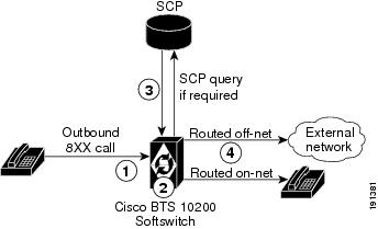
The purpose of the toll-free feature is to have the called party, rather than the calling party, charged for the call. These calls are prefixed with the 1+8XX service access codes. The seven digits following the 8XX codes are used for routing the call. For an inbound/outbound 8XX call, the Cisco BTS 10200 Softswitch checks the local toll-free database first. If the corresponding DN is not found in the local toll-free database, the system sends a query to the service control point (SCP) to request the corresponding DN.
All aspects of toll-free calling are transparent to the caller. A caller expects to dial 1-8XX-NXX-XXXX to reach the desired destination. The company that translates the number to a specific DN, and the company that routes the call, must appear transparent to callers. Most callers are not aware that their dialed 8XX number is changed into a specific DN. What matters to the callers is that they reach what they perceive to be the called number, and they are not billed for the call.
Note
8XX Call Processing
The system processes outbound 8XX calls as follows:
1.
2.
3.
Note
4.
Note
Figure 1-1 shows the processing of an outbound 8XX call placed by a subscriber.
Figure 1-1 Processing of an Outbound 8XX Call
Notes for Figure 1-11.
2.
3.
4.
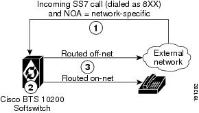
Figure 1-2 shows the processing of an 8XX call received from the network with a network-specific NOA.
Figure 1-2 Processing of an 8XX Call with a Network-Specific NOA
Notes for Figure 1-21.
2.
3.
Local Toll-Free Database
This section explains how the system uses information from the local toll-free database.
The Cisco BTS 10200 Softswitch provides the ability to translate inbound/outbound 8XX numbers at the Feature Server (FS) using a local 8XX database. The 8XX service supports the following features:
•
•
•
•
•
The Cisco BTS 10200 Softswitch also supports optional DNIS service. In an 8XX DNIS service, when a call is terminated to a PBX (call center), 4 digits are outpulsed to the PBX to identify the originally dialed 8XX number. In case of custom DNIS, up to 22 digits can be outpulsed with additional information such as:
•
•
•
When a translated number (for an original 8XX call) is received, the Analyzed Info DP triggers the FS. The Cisco BTS 10200 Softswitch looks up the DNIS and TG information for the call. The DNIS information is then outpulsed to the PBX. If an overflow condition is encountered, the call is routed to the overflow trunk. The overflow trunk can be a PSTN trunk.
See SR-2275, Telcordia Notes on the Network, Section 14.6 for additional information on toll-free database services.
SCP-Based Toll-Free Services
This section explains how the system uses information from the external toll-free database.
The Cisco BTS 10200 Softswitch communicates with an SCP-based database called the toll-free database service, which contains information for routing the call. The database service provides information about the network service provider selected to complete the call, and information for translating the toll-free number to a specific 10-digit directory number (DN). The routing of the call can vary depending on the arrangements made between the toll-free subscriber and the network service provider. These arrangements can include selective routing based on the time of day, day of week, and location from which the call originates.
Provisioning Commands
To provision this feature, see the 8XX (Toll-Free Calling) provisioning procedure in the Cisco BTS 10200 Softswitch Provisioning Guide.
Active Call Information Display
The Cisco BTS 10200 Softswitch allows the service provider to display information about an active (in-progress) call (originating or terminating). The implementation is based on Telcordia document GR-529-CORE, Call Tracing (FSD 15-03-000). The display is performed using a CLI query command.
The input parameter can be any subscriber-specific or trunk-specific information including:
•
–
–
–
–
–
•
–
–
–
The system output (display) includes available information about the calling and called parties (for example, calling number, called number, call state, trunk type, call ID, charge number, and redirected number). The system supports both brief and verbose display modes.
Note
Alerting Notification to Third-Party Feature Server
The Cisco BTS 10200 Softswitch can be provisioned to deliver alerting notification (notification of power ringing or call-waiting tone on the subscriber line) and call data to a third-party feature server (3PTYFS). This feature is available for both off-net-to-on-net calls and on-net-to-on-net calls. It can be assigned globally (for all subscribers on the switch), on a per-POP basis, or for individual subscribers. The service provider can use appropriately designed and configured feature servers to make use of this notification and data to provide value-added services to subscribers; for example, delivery of caller ID on a subscriber television or computer screen.
Note
Note
Background Information
Alerting Notification was originally introduced in Release 3.5.4. In Release 4.5.x, this feature supports advertising of an externally addressable FQDN to an external third-party feature server when necessary. Previously, the FQDN advertised in Contact and Via headers in a SIP INVITE message resolved to an internal management network IP address. In addition, Release 4.5.x supports the provisioning of this feature on a per-POP basis.
Call Flow
The call flow works as follows:
1.
2.
3.
Alerting Notification has no impact on the setup or progress of the call. The Cisco BTS 10200 Softswitch continues with normal call processing regardless of any response from the 3PTYFS.
Prerequisites
The Cisco BTS 10200 Softswitch locates the 3PTYFS via a TSAP address that is provisioned in the Cisco BTS 10200 Softswitch database. If the TSAP address is a domain name, the domain name must also be configured in the service provider domain name system (DNS) server.
The Cisco BTS 10200 Softswitch advertises its own TSAP address to the 3PTYFS. There are specific requirements for entering this information during initial software installation. For details, see the "Installation Considerations" section.
The 3PTYFS should be provisioned to support this feature in accordance with the applicable product documentation. The Cisco BTS 10200 Softswitch does not send any provisioning or status/control commands to the 3PTYFS.
Caution
Caution
Restrictions and Limitations
CALL_ACCEPTED_NOTIFY Trigger Sent for Incoming Calls to Subscribers OnlyThe system sends the CALL_ACCEPTED_NOTIFY trigger to the 3PTYFS only if the called party is a subscriber on the Cisco BTS 10200 Softswitch. This is true even if the feature is provisioned globally (at the office level) on the Cisco BTS 10200 Softswitch.
Limitations when Calling Party Is Using Certain SIP and H.323 DevicesSome calling-party devices (certain SIP- and H.323-based endpoints) may not send an explicit alerting indication (180 Ringing for SIP and Alerting for H.323). In these cases, the Call Agent does not report the CALL_ACCEPTED_NOTIFY trigger to the 3PTYFS.
Subsequent TriggersThe Cisco BTS 10200 Softswitch does not send updated information to the 3PTYFS based on subsequent triggers in the call (following the CALL_ACCEPTED TDP). For example, if a user hangs up while another call is on hold (in call-waiting mode) and the phone is rung again, the Cisco BTS 10200 Softswitch does not report a trigger and does not send any data.
NAPTER and SRV Record Lookup Not SupportedThis feature does not support the use of the Naming Authority Pointer (NAPTR) or DNS services (SRV) records for lookup of the 3PTYFS domain name. The DNS server must be populated with the address (A) record for the fully qualified domain name (FQDN) specified in the TSAP address of the 3PTYFS.
Status and Control CommandsThe status feature-server command reports the status of feature server components internal to the Cisco BTS 10200 Softswitch. However, the Cisco BTS 10200 Softswitch does not send any status or control commands to the 3PTYFS.
Installation Considerations
For Alerting Notification to function correctly, specific data must be entered into the opticall.cfg file at the time of initial Cisco BTS 10200 Softswitch software installation. The choice of data depends on whether the 3PTYFS will be deployed in the same private (internal) management network as the Cisco BTS 10200 Softswitch, or in a public network.
•
•
This installation data also affects the provisioning requirements for the 3PTYFS in the Feature Server table:
•
•
Note
Note
Calling Party Number Options for Outgoing SETUP Messages
The Cisco BTS 10200 Softswitch provides options for controlling the calling party number (CPN) data sent in the outbound SETUP message on calls outbound or redirected from the Cisco BTS 10200 Softswitch to the PSTN.
Option to Send Billing DN as CPN for Outgoing Calls
The system has a provisionable option for sending a subscriber billing DN (or main DN of a PBX subscriber) as the CPN in outgoing SETUP messages on outgoing nonemergency calls. This is provisionable using the SEND-BDN-AS-CPN token in the Subscriber table.
•
•
Note
Option to Send Billing DN as CPN for Emergency Calls
The system has a provisionable option for sending a subscriber billing DN (or main DN of a PBX subscriber) as the CPN in outgoing SETUP messages on outgoing emergency calls. This is provisionable using the SEND-BDN-FOR-EMG token in the Subscriber table.
Note
•
•
Option to Send Redirecting Number as CPN for Redirected Calls
This feature allows the service provider to control the CPN data sent in the outbound SETUP message on redirected calls outbound from the Cisco BTS 10200 Softswitch to the PSTN.
The CPN option is provisionable (via CLI commands) using the SEND-RDN-AS-CPN token in the TRUNK-GRP table:
•
•
N is the default value.This feature is applicable to the following scenarios:
•
•
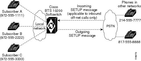
Figure 1-3 shows an example of the networks and phones involved in redirection by a subscriber phone. Table 1-4 explains how to provision the SEND-RDN-AS-CPN token for various call-redirection scenarios and results.
Figure 1-3 General Network View for Redirection by a Subscriber Phone
Table 1-4 Provisioning SEND-RDN-AS-CPN Token in TRUNK-GRP Table for Redirection by a Subscriber Phone
CPN and RDN
Data
(Example)
Provisioned for SEND-RDN-
AS-CPN
Outbound
SETUP
MessageOn-net to off-net call (either of the following):
A -> B -> fwd -> C -> fwd -> off-net
A -> C -> fwd -> off-net
CPN=
972-555-1111RDN=
972-555-3333Y
Overwrite CPN
with RDNCPN=
972-555-3333RDN=
972-555-3333N
Do not change CPN
CPN=
972-555-1111RDN=
972-555-3333Off-net to on-net to off-net call:
Inbound off-net call -> B -> fwd -> off-net
Note
(from the incoming SETUP message)
is 817-555-8888.
The new RDN is the DN of the forwarding phone, Subscriber B—972-555-2222.CPN=
214-555-7777RDN=
817-555-8888(from incoming SETUP message)
Y
Overwrite CPN
with RDNCPN=
972-555-2222RDN=
972-555-2222N
Do not change CPN
CPN=
214-555-7777RDN=
972-555-2222
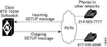
Figure 1-4 shows an example of the networks and phones involved in redirection of a basic or Tandem call. Table 1-5 explains how to provision the SEND-RDN-AS-CPN token for call-redirection scenarios and results. Note that the content of the outbound SETUP message depends on whether the RDN is available in the incoming SETUP message.
Figure 1-4 General Network View for Redirection of Basic or Tandem Call
Table 1-5 Provisioning SEND-RDN-AS-CPN Token in TRUNK-GRP Table for Redirection of Basic or Tandem Call
CPN and RDN
Data
(Example)
Provisioned for SEND-RDN-
AS-CPN
Outbound
SETUP
MessageOff-net to off-net call (basic or Tandem)
with RDN available in the incoming
SETUP message:off-net call -> Cisco BTS 10200 Softswitch
-> off-netCPN=
214-555-7777RDN=
817-555-8888(from incoming SETUP message)
Y
Overwrite CPN
with RDNCPN=
817-555-8888RDN=
817-555-8888N
Do not change CPN
CPN=
214-555-7777RDN=
817-555-8888Off-net to off-net call (basic or Tandem)
with RDN not available in the incoming
SETUP message:off-net call -> Cisco BTS 10200 Softswitch
-> off-netCPN=
214-555-7777RDN not available
(from incoming SETUP message)
Y
Do not change CPN
CPN=
214-555-7777RDN not available
N
Do not change CPN
CPN=
214-555-7777RDN not available
Tip
Dialing Parity (IntraLATA Toll Presubscription)
The Cisco BTS 10200 Softswitch supports this feature in accordance with Telcordia document GR-693-CORE, LSSGR: Presubscription Indication (FSD 20-24-0000).
Dialing parity—also known as intraLATA toll presubscription—allows subscribers to select a telecommunications company for intraLATA calls (local toll calls) in the same way they select a long-distance provider. With dialing parity, subscribers are able to dial the number they want and have a preselected carrier—a competitive local exchange carrier (CLEC), incumbent local exchange carrier (ILEC), or a long-distance carrier—automatically handle the call if it is a local (intraLATA) toll call. Preselecting a local toll carrier eliminates the need for dial-around service for local toll calls (101XXXX numbers). Prior to implementation of dialing parity, long-distance carriers provided intraLATA service by dialing around an ILEC or CLEC via 101XXXX numbers (carrier access codes—CACs).
Local access and transport areas (LATAs) were created after the breakup of the AT&T system. LATAs are also known as called service areas or local toll calling areas. CLECs and ILECs provide two types of calls to their subscribers within the LATA:
•
•
Local toll calls are typically calls to places more than 16 miles from the subscriber location in urban areas and more than 13 miles in rural areas. Local toll calls do not qualify as either local or long distance—they are between the two and are subject to different rates.
Local Number Portability (LNP)
The Cisco BTS 10200 Softswitch supports local number portability (LNP) for North American and ITU-based systems. For general information, see Number Portability Switching Systems, T1.TRQ-02-2001, which provides unofficial agreement within T1S1. T1S1 is the ATIS accredited body for signaling. This document is available at http://www.atis.org.
LNP permits subscribers who change their local phone company to keep their existing telephone numbers. An FCC order requires this feature in the 100 top metropolitan service areas in the United States. LNP permits calls to be routed to the subscriber's new local switch without any particular per-call action required of either the calling or called party. Each switch contains a database of the office codes (NPA-NXXs) associated with subscriber numbers that have been ported in and ported out.
Note
The Cisco BTS 10200 Softswitch supports the LNP function as follows:
•
•
•
–
–
–
For a comprehensive description of LNP functions and provisionable parameters, see the Cisco BTS 10200 Softswitch Dial Plan.
To provision LNP options, see the appropriate procedures from the list below:
•
•
•
•
Split-NPA
When DNs are exhausted within an NPA, an additional NPA is assigned to the region. The new NPA may be allocated as an overlay over the existing NPA, in which case there is no major impact to the Cisco BTS 10200 Softswitch. However, when the new NPA is assigned based on a geographical split of the region, there are significant impacts. The assignment of the new NPA based on a geographical split is referred to as split-NPA.
The split-NPA feature impacts both provisioning (EMS) and call processing subsystems in the Cisco BTS 10200 Softswitch. Several provisioning tasks must be performed to introduce a new NPA into a region, including:
•
•
•
Note
Before the permissive period begins, subscribers affected due to the split-NPA can be reached only via the old NPA. Duplicate records for both old and new NPA are created before the permissive period begins.
During the permissive period, both old and new NPA can be dialed (10-digit dialing is required to reach a subscriber in the affected NPA). The subscriber (ANI) and subscriber feature data records are updated to the new NPA during the permissive period.
Once the permissive period ends, subscribers affected due to the split-NPA can be reached only via the new NPA. This is referred to as the mandatory dialing period for the new NPA. The duplicate records created before the permissive period are cleaned up after the mandatory period begins.
For additional information on split-NPA, see the ATIS document INC97-0404-016, NPA Code Relief Planning & Notification Guidelines.
Note
Tip
T.38 Fax Relay
In previous releases, the Cisco BTS 10200 Softswitch partially supported T.38 fax relay call agent controlled mode on MGCP and H.323 interfaces. Release 4.5.x supports the PacketCable environment (eMTA subscribers), as well as extending T.38 fax support to SIP, NCS, and TGCP interfaces. The support is for both the line and trunk side of SIP, and interworks with the existing T.38 support over MGCP line and trunk side, and H.323 trunk side.
The Cisco BTS 10200 Softswitch supports ITU-T T.38 procedures on the following interfaces:
•
•
•
•
T.38 fax is supported for the following H.323 configurations:
–
–
–
–
–
•
•
Following is a list of industry references for T.38 fax relay
•
•
•
•
List of T.38 Fax Topics Covered in this Section
This section covers the following system capabilities:
•
•
•
•
•
•
•
MGCP/NCS Interface—Fax Modes Supported
The system supports the following fax procedures from the MGCP or NCS endpoint:
•
•
•
SDP Attributes Support for T.38 Fax Relay
The system supports the exchange of media path (SDP or H.245) attributes between the Cisco BTS 10200 Softswitch managed end devices used to support T.38. These attributes are:
•
•
MTA DQOS Support for T.38 Fax Relay
There are DQOS considerations for NCS MTA subscribers when switching between audio and T.38 codec. The Cisco BTS 10200 Softswitch follows the DQOS flow characteristics for T.38 sessions described in PacketCable specification "pkt-sp-codec."
For DQOS, the Cisco BTS 10200 Softswitch creates new gates for the T.38 codec when switching to T.38 media, because endpoints can change their media IP and ports when switching between audio and T.38.
Fallback to Audio Media on T.38 Negotiation Failure
The system supports audio fallback on all interfaces supporting T.38 fax. Failure to negotiate T.38 media occurs when the non-fax detecting endpoint fails a request to modify the connection (MDCX) to T.38, and the MDCX contained a T.38 remote connection descriptor (SDP) from the fax-detecting end. When this occurs, a counter increments to track the event occurrences. Any other T.38 procedure fail scenarios do not trigger the fall back procedure. Instead, the call is cleared by the endpoint.
Audio fall back on T.38 negotiation failure requires a collaborative support by the endpoints. The MGCP/NCS endpoints requirements are:
Non-Fax Detecting Endpoint
When the non-fax detecting endpoint fails the MDCX request to modify the connection to T.38, and this MDCX contained a T.38 remote connection descriptor (SDP) from the fax-detecting end, then the non-fax detecting endpoint continues with its current audio media settings.
Fax Detecting Endpoint
When the non-fax detecting endpoint fails a switch to T.38, the fax-detecting endpoint is still in T.38 media mode. The Cisco BTS 10200 Softswitch sends an MDCX to the fax detecting endpoint to abort T.38 procedures and revert back to previous audio media. The fax detecting endpoint responds with an audio SDP, and the Cisco BTS 10200 Softswitch exchanges this SDP with the remote end.
The Cisco BTS 10200 Softswitch applies the following recommendation, forecast as an update, to the MGCP FXR Package. However, it does not send the "off" Fax LCO to abort T.38 procedures. Instead, it sends an "L:<previous codec>" LCO.
For remote SIP endpoints or gateways sending a Re-Invite with T.38 SDP to switch to T.38 media receiving a fail response should fall back to previous SDP settings.
For H.323 calls, if the non-H.323 endpoint fails to switch to T.38 fax while the H.323 side is already switched to T.38 fax, then the H.323 side reapplies H.245 procedure to return to audio codec.
Audio Restore After Successful T.38 Fax Transmission
The Cisco BTS 10200 Softswitch can restore audio media after successful T.38 fax transmission. However, this feature is beyond the scope of the FXR package, and requires collaborative support by the endpoints.
For the Cisco BTS 10200 Softswitch to provide this feature, the MGCP/NCS endpoints must complete the following:
•
•
T.38 Glare Handling
The Cisco BTS 10200 Softswitch applies a call agent controlled switch to T.38 fax media when initiated by either the originating or terminating endpoint. This includes the scenario in which both endpoints initiate the switch, causing a glare condition at the Cisco BTS 10200 Softswitch.
For details about glare handling, contact your Cisco support representative.
SDP Attributes Encoding Formats
SDP capability attributes can be formatted two ways when sent from the Cisco BTS 10200 Softswitch out of the network using MGCP, NCS and SIP protocols.
•
In this method, SDP is encoded:
a=sqn: 0a=cdsc: 1 audio RTP/AVP 0 18 96a=cpar: a=fmtp:96 0-16,32-35a=cdsc: 2 image udptl t38•
In this method, SDP is encoded:
a=X-sqn:0a=X-cap: 1 audio 0 18 96a=X-cpar: a=fmtp:96 0-16,32-35a=X-cap: 2 image udptl t38The Cisco BTS 10200 Softswitch selects the encoding method based on following guidelines:
•
•
•
SIP Support for Call Legs
The system supports T.38 fax relay call agent controlled mode to SIP lines and trunks where one or both call legs are SIP. In addition to passing the SDP advertisement of T.38 fax codec, the Cisco BTS 10200 Softswitch issues a re-invite or similar SIP method to change the codec of an established session to a T.38 fax relay codec session once the fax event is detected (such as operating in a call agent controlled mode).
This has a dependency on SIP CPEs and media gateways. Cisco recommends that the T.38 session is initiated by the terminating side of endpoints.
For more information, refer to ITU T.38 03/2002.
Protocol Interworking
The Cisco BTS 10200 Softswitch supports T.38 for both SIP lines and SIP trunks, and interworking with the following protocols as either terminating or originating:
•
•
•
After the fax is done, the call falls back to a voice call.
The detailed protocol interworking matrix is shown in Table 1-6.
.
Table 1-6 Protocol interworking matrix
H.323 trunk
X
X
X
MGCP (eMTA using NCS)
X
X
X
SIP line and trunk 1
X
X
X
1 SIP line support for T.38 fax is provided in Release 4.5.1 only.
Figure 1-5 shows an example of MGCP and SIP interworking.
Figure 1-5 Example of MGCP and SIP Interworking for T.38 Fax
Control Configuration
The Cisco BTS 10200 Softswitch can be configured with either call agent controlled T.38 mode or gateway controlled T.38 mode.
Restrictions and Limitations
T.38 fax relay has some limitations in Release 4.5.x, including:
•
•
•
•
•
•
•
Cisco BTS 10200 Softswitch Unsupported T.38 Fax Transport Methods
The Cisco BTS 10200 Softswitch does not support following T.38 fax transport methods from ITU-T T.38:
•
•
Cisco BTS 10200 Softswitch Unsupported T.38 Interface
Support for ITU-T T.38 procedures are not provided on the following interfaces managed by the Cisco BTS 10200 Softswitch (including the interworking between supported and unsupported interfaces):
•
•
•
MGCP/NCS Interface—T.38 Fax Modes Unsupported
The Cisco BTS 10200 Softswitch does not support the following MGCP FXR package defined T.38 fax modes from the MGCP/NCS endpoint:
•
•
•
If the Cisco BTS 10200 Softswitch does not signal any FXR fax mode in the Local Connection Options, including "Off" mode, the gateway can engage in Gateway mode. If this occurs, the Cisco BTS 10200 Softswitch does not receive any Gateway mode notification events from the endpoint because it does not request them. The Cisco BTS 10200 is not notified of the gateway mode activity. The Cisco BTS 10200 Softswitch honors the FXR package requirements during gateway mode by not interfering with the gateway procedures in this case.
Relationship Between T.38 Fax Transmission and Call Features on the Cisco BTS 10200 Softswitch
The Cisco BTS 10200 Softswitch makes no distinction between calls using audio and calls using fax transmission with respect to call features.
Cisco recommends that Cisco BTS 10200 Softswitch subscribers disable the Call Waiting feature before making a call for fax transmission. This protects against any interruptions during fax transmission.
In certain multi-party call feature scenarios, such as three-way calling where a user has engaged the three-way call feature on Cisco BTS 10200 Softswitch and one party attempts a switch to T.38 fax, the endpoint fails to switch the call to T.38. The party may be either disconnected or reverted back to audio depending on the endpoints capabilities.
End-to-End SDP Exchange for T.38 Media and the H.323 Interface
The H.323 protocol must negotiate T.38 fax connection attributes (example: bit rate, maximum buffer size) during the voice call establishment using Terminal Capability Set (TCS) messages. However, for SIP and MGCP, the endpoint does not report T.38 fax connection attributes until the fax actually starts. When this occurs from an interworking H.323 endpoint to a SIP/MGCP interface, and the H.323 endpoint is ready to send TCS message during voice call establishment phase, the T.38 fax attributes are not available from the SIP/MGCP interface.
To overcome this interworking limitation, all Cisco IOS gateways assume the defaults for these attributes while exchanging TCS messages. Cisco BTS 10200 follows the same philosophy for H.323 to/from MGCP/NCS and H.323 to/from SIP calls. Cisco BTS 10200 assumes following defaults:
•
•
•
•
•
•
•
•
To overcome other interworking limitations with SIP, IOS H.323 gateways send the fax UDP port in H.245 Open Logical Channel (OLC) messages. A provisioning field (REMOTE_FAX_PORT_ RETRIEVAL_MSG) is added in h323-tg-profile and h323-term-profile, enabling the H.323 interface to read remote endpoint's fax UDP port either from OLC message or from OLC Ack message.
Note
Internet Fax Terminal Endpoint Types—Not Supported
The Cisco BTS 10200 Softswitch does not support endpoints that negotiate for T.38 media on initial call setup. These endpoints include internet fax terminals or internet-aware fax devices, and internet telephony gateways that only support T.38 real-time fax communications (by design or by configuration), or are statically configured to support T.38 fax calls only.
Cisco BTS 10200 Handling of T.38 Failure Event Notification from an MGCP or NCS Endpoint
The Cisco BTS 10200 Softswitch releases the call if the MGCP or NCS fax-detecting endpoint issues a "t38(failure)" event. This event is sent by the endpoint when it encounters some kind of problem with the T.38 fax relay procedure as stated in the MGCP FXR package.
Feature Provisioning Commands
Provisioning commands are available in the Cisco BTS 10200 Softswitch Provisioning Guide.
Tip
Trunk and Line Testing
This section describes trunk and line testing features, and includes the following topics:
•
•
•
Note
Trunk Testing
Trunk testing is used to evaluate the transmission quality of the shared trunks that interconnect switching systems. Trunk testing is extremely important in monitoring system health, because it is the only practical way to objectively evaluate the performance of individual trunks.
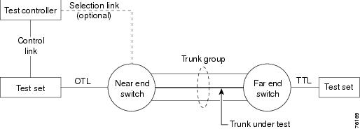
Trunk testing requires the following equipment and test lines. (Some additional types of equipment and lines may also be used.) A basic system setup is shown in Figure 1-6.
•
•
•
•
Figure 1-6 Trunk Testing Setup
Near End Test Origination Test Calls
The Cisco BTS 10200 Softswitch supports calls used to test individual trunks that connect a local gateway with a gateway or PSTN switch at a remote office. The Cisco BTS 10200 Softswitch supports OTL and TTL capability. User-provided test equipment and, optionally, test controllers may be connected to the test lines. Proper selection of test equipment and test functions helps to ensure interoperability between different carriers.
Note
The process for testing a Cisco BTS 10200 Softswitch OTL is as follows:
1.
2.
3.
4.
–
–
The complete trunk address in this example is 00030018.
–
The technician dials KP-00030018-104-ST.
5.
The complete test string in this example is PREFIX | 00030018 | 9581104 | END.
Note
6.
7.
1xx Test Line Support
When the Cisco BTS 10200 Softswitch is the near-end switch, the following process takes place at the remote switch:
1.
2.
3.
When the Cisco BTS 10200 Softswitch is supporting the TTL capability (test call originated at another switch), the process is as follows. The Cisco BTS 10200 Softswitch receives the 958 or 959 call, recognizes the 958 or 959 type, and routes the test to the appropriate test line.
With Release 4.5.x, the Cisco BTS 10200 Softswitch supports the capability for a TDM-based testing device to perform continuity testing over an MF CAS TDM trunk interface. This capability requires that an MGCP-based trunking gateway is present in the test path. The TDM test type is the traditional 1xx test type, with an additional enhancement in Release 4.5.x—the ability to route the test call to a specified DN on a given trunk circuit.
T108 Test Line Support
The T108 test line feature determines the performance of trunks connecting digital exchange switches, including voice over packet (VoP) softswitches. Cisco BTS 10200 Softswitch incoming trunks requesting other 1xx-type test lines are routed to shared test lines for the requested tests, regardless of which gateway terminates the trunk or which gateway/IAD terminates the test line. The T108 test line feature requests a test to be performed within the same gateway where the trunk under test (TUT) is terminated, and provides a digital loopback within the gateway. The T108 test line feature supports manual and automated testing.
The T108 test line sequence is as follows:
1.
2.
3.
4.
5.
6.
Note
Testing Capability for 911 FGD-OS Trunks
When turning up 911 Feature Group D Operator Services (FGD-OS) trunks, there is an exchange of Off-hook/On-hook signaling and the passing of tone back and forth without a complete call setup. Signaling for this function is based on the MGCP MO package.
Upon receiving a CLI command or Test Access request, Cisco BTS 10200 Softswitch sends the request to the gateway via MGCP signaling to trigger the test capability on 911 trunk at the gateway (not part of a call setup sequence). The Cisco BTS 10200 Softswitch reports the result to the operator upon receiving the notification from the gateway (for example, receiving off-hook or on-hook notification). Once this gateway test capability on a 911 trunk is in place, it can be invoked remotely across the MGCP interface associated with the Cisco BTS 10200 Softswitch.
Note
Network Loopback Test for NCS/MGCP Subscriber Endpoints
This feature supports the capability for a testing device to perform network loopback tests from any line-side NCS/MGCP Residential Gateway or Media Termination Adapter (MTA). The loopback tests can be initiated from designated test endpoints (subscribers) controlled by the Cisco BTS 10200 Softswitch. The procedure for setting up the test includes configuring the test lines as subscriber terminations and provisioning the MGW parameters. The system allows NCS/MGCP endpoints in a trunk group to be provisioned as a test trunk group with specific test attributes.
Restrictions and Limitations
The following restrictions and limitations apply:
•
•
•
•
Configuring and Operating
The procedures for configuring the lines and gateways, and the procedure for performing the tests, are described in the Network Loopback Test section of the Cisco BTS 10200 Softswitch Troubleshooting Guide.
Network Loopback Test for ISDN PRI Trunks (Release 4.5.1, MR1)
This feature allows operators to conduct network loopback testing originating from shared ISDN PRI trunks. The shared test trunk group accepts both normal and test calls. Test calls are identified by provisioning the call-type and call-subtype tokens in the Destination table. For detailed requirements and procedures for running this type of trunk test, see the Cisco BTS 10200 Softswitch Troubleshooting Guide.