-
Troubleshooting Guide
-
Preface
-
Chapter 1 - Troubleshooting Overview
-
Chapter 2 - Audit Troubleshooting
-
Chapter 3 - Billing Troubleshooting
-
Chapter 4 - Call Processing Troubleshooting
-
Chapter 5 - Configuration Troubleshooting
-
Chapter 6 - Database Troubleshooting
-
Chapter 7 - Maintenance Troubleshooting
-
Chapter 8 - Operations Support System Troubleshooting
-
Chapter 9 - Security Troubleshooting
-
Chapter 10 - Signaling Troubleshooting
-
Chapter 11 - Statistics Troubleshooting
-
Chapter 12 - System Troubleshooting
-
Chapter 13 - Network Troubleshooting
-
Chapter 14 - General Troubleshooting
-
Chapter 15 - Diagnostic Tests
-
Chapter 16 - Disaster Recovery Procedures
-
Chapter 17 - Disk Replacement
-
Appendix A - Recoverable and Nonrecoverable Error Codes
-
Appendix B - System Usage of MGW Keepalive Parameters
-
Glossary
-
 Feedback
Table Of Contents
Signaling System 7 Trunk Termination Tests
Integrated Services Digital Network Trunk Termination Tests
Channel-Associated Signaling Trunk Termination Tests
Announcement Trunk Termination Tests
Query Verification Tool and Translation Verification Tool
Query Verification Tool Measurements
Translation Verification Tool Measurements
Using Query Verification Tool and Translation Verification Tool Together
Network Loopback Test for Network-based Call Signaling/Media Gateway Control Protocol Endpoints
Configuring the Originating Trunk Group
Session Initiation Protocol Subscriber Registration Status Check
Database Out of Synchronization
Call Agent Configuration Table
Line Loopback Tests over an ISDN Trunks
Trunk Loopback Tests over an ISDN Trunk
Measurement Data Transport and Access
Measurement Data Event Reports
Provisioning Measurement Report Types
Reporting Current Interval Counts
Clearing Current Interval Counts
Session Initiation Protocol Counters
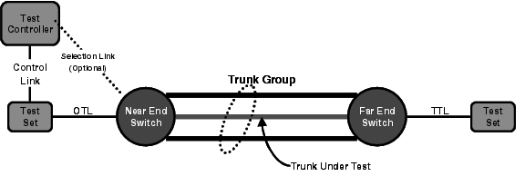
Cisco BTS 10200 Originating Test Line
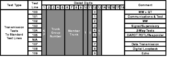
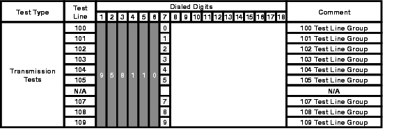
Trunk Access and Test Termination Number Format
Cisco BTS 10200 Terminating Test Line
Near End Test Origination Test Line
Trunk Access and Test Termination Number Format
101 Test-Communications and Test
103 Test-Signaling and Supervisory
107 Test Line-Data Transmission
Diagnostic Tests
Revised: July 22, 2009, OL-8000-32Introduction
This chapter describes diagnostic tests that can be performed on media gateways, subscriber terminations, and trunk terminations. All media gateways, subscriber and trunk terminations must be in the MAINT state for testing. The following tests are described in this section:
•
Signaling System 7 Trunk Termination Tests
•
•
•
•
•
•
Caution
Media Gateway Tests
This section describes the tests that can be performed on media gateways. A gateway must be in the MAINT state.
Step 1
control mgw id=c2421.65; mode=forced; target-state=maint;Reply Example:
Reply : Success: CLI change successfulMGW ID -> c2421.65INITIAL STATE -> ADMIN_INSREQUEST STATE -> ADMIN_MAINTRESULT STATE -> ADMIN_MAINTFAIL REASON -> ADM found no failureREASON -> ADM executed successfulRESULT -> ADM configure result in successStep 2
diag mgwReply Example:
Reply: Diagnostic MGW Menu.===(1) MGW Network Connectivity Test(2) MGW MGCP Connectivity Test(3) ALL
Note
Test #2 tests if Media Gateway Control Protocol (MGCP) has access to the device.
Test #3 performs tests 1 and 2.Step 3
diag mgw id=ubr-03; test=1;Reply Example:
MEDIA GATEWAY LINE DIAGNOSTIC TEST EXECUTED -> diag mgwID -> ubr-03TEST-TYPE -> ADM-MGW-NETW-CONNECTIVITY-TESTTEST-DURATION -> 0RESULT -> TEST-SUCCESSREASON -> PASSEDReply: Diagnostic command executed.diag mgw id=ubr-03; test=2;Reply Example:
MEDIA GATEWAY LINE DIAGNOSTIC TEST EXECUTED -> diag mgwID -> ubr-03TEST-TYPE -> ADM-MGW-MGCP-CONNECTIVITY-TESTTEST-DURATION -> 0RESULT -> TEST-SUCCESSREASON -> PASSEDReply: Diagnostic command executed.diag mgw id=ubr-03; test=3;Reply Example:
MEDIA GATEWAY LINE DIAGNOSTIC TEST EXECUTED -> diag mgwID -> ubr-03TEST-TYPE -> ADM-MGW-NETW-CONNECTIVITY-TESTTEST-DURATION -> 11RESULT -> TEST-SUCCESSREASON -> PASSEDMEDIA GATEWAY LINE DIAGNOSTIC TEST EXECUTED -> diag mgwID -> ubr-03TEST-TYPE -> ADM-MGW-MGCP-CONNECTIVITY-TESTTEST-DURATION -> 0RESULT -> TEST-SUCCESSREASON -> PASSEDReply: Diagnostic command executed.Step 4
control mgw id=c2421.65; mode=forced; target-state=ins;Reply Example:
Reply : Success: CLI change successfulMGW ID -> c2421.65INITIAL STATE -> ADMIN_MAINTREQUEST STATE -> ADMIN_INSRESULT STATE -> ADMIN_INSFAIL REASON -> ADM found no failureREASON -> ADM executed successfulRESULT -> ADM configure result in success
Subscriber Termination Tests
This section describes the tests that can be performed on subscriber terminations. All terminations must be in the MAINT state.
Step 1
control subscriber-termination id=sub2-ctx2; mode=forced; target-state=maint;Step 2
diag subscriber-termination;Reply Example:
Reply: Diagnostic Subscriber Menu.===(1) Subscriber MGCP Connectivity Test(2) Subscriber Termination Connection Test(3) Subscriber Termination Ring Test(4) ALL
Note
Test #2 tests if there is a path to the device (ping).
Test #3 tests if the subscriber can be rung. The Ring parameter must be specified in seconds for this test. The default is 5 seconds.
Test #4 performs tests 1 through 3.Step 3
diag subscriber-termination id=sub2-ctx2; test=1;Reply Example:
SUBSCRIBER LINE DIAGNOSTIC TEST EXECUTED -> diag subscriber-terminationID -> sub2-ctx2TEST-TYPE -> ADM-MGW-MGCP-CONNECTIVITY-TESTTEST-DURATION -> 10RESULT -> TEST-SUCCESSREASON -> PASSED: Reason: AUEP-NACK received with RespCode = 510Reply: Diagnostic command executed.diag subscriber-termination id=sub-ubr3-1@cisco.com; test=2;Reply Example:
SUBSCRIBER LINE DIAGNOSTIC TEST EXECUTED -> diag subscriber-terminationID -> sub-ubr3-1@Cisco.comTEST-TYPE -> ADM-TERM-CONNECTION-TESTTEST-DURATION -> 55RESULT -> TEST-SUCCESSREASON -> PASS successfully.Reply: Diagnostic command executed.diag subscriber-termination id=sub-ubr3-1@cisco.com; test=3; ring-duration=10;Reply Example:
SUBSCRIBER LINE DIAGNOSTIC TEST EXECUTED -> diag subscriber-terminationID -> sub-ubr3-1@Cisco.comTEST-TYPE -> ADM-TERM-RING-TESTTEST-DURATION -> 9989RESULT -> TEST-SUCCESSREASON -> PASSEDReply: Diagnostic command executed.
Note
Step 4
control subscriber-termination id=sub2-ctx2; mode=forced; target-state=ins;
Signaling System 7 Trunk Termination Tests
This section describes the tests that can be performed on Signaling System 7 (SS7) trunk terminations. All terminations must be in the MAINT state for testing.
Step 1
control ss7-trunk-termination tgn-id=103; mode=forced; target-state=maint;
Note
Step 2
diag ss7-trunk-terminationReply Example:
Reply: Diagnostic SS7 Trunk Group Menu.===Test=1: SS7 MGCP ConnectivityTest=2: SS7 Termination Connection TestTest=3: COTTest=4: CQMTest=5: CVTTest=6: CICTest=7: All
Note
Test #2 tests if there is a path to the device (ping).
Test #3 tests the integrity of the SS7 Bearer Path.
Test #4 queries the SS7 circuit (or group of circuits) status. A range of CICs can be specified (to a maximum of 24). Both remote and local trunk states are displayed in the results.
Test #5 tests to ensure that each end of the circuit has sufficient and consistent information for using the circuit in call connections. Common language location identifier (CLLI) names are included.
Test #6 tests to ensure the CIC connections.
Test #7 performs tests 1 through 6.Step 3
diag ss7-trunk-termination tgn-id=103; cic=13; test=1;Reply Example:
TRUNK DIAGNOSTIC TEST EXECUTED -> diag trunkTG-NUM -> 103CIC -> 13TEST-TYPE -> ADM-MGW-MGCP-CONNECTIVITY-TESTTEST-DURATION -> 0RESULT -> TEST-SUCCESSREASON -> PASSED: Reason: AUEP-NACK received with RespCode = 510Reply: Diagnostic command executed.diag ss7-trunk-termination tgn-id=103; cic=13; test=2;Reply Example:
TRUNK DIAGNOSTIC TEST EXECUTED -> diag trunkTG-NUM -> 103CIC -> 13TEST-TYPE -> ADM-TERM-CONNECTION-TESTTEST-DURATION -> 33RESULT -> TEST-SUCCESSREASON -> PASS successfully.Reply: Diagnostic command executed.diag ss7-trunk-termination tgn-id=103; cic=14; test=3;Reply Example:
TRUNK DIAGNOSTIC TEST EXECUTED -> diag trunkTG-NUM -> 103CIC -> 14TEST-TYPE -> ADM-SS7-COT-TESTTEST-DURATION -> 0RESULT -> TEST-FAILUREREASON -> ADM-MAINT-STATE-REQUIREDReply: Diagnostic command executed.diag ss7-trunk-termination tgn-id=2;cic=1-24;test=4Reply Example:
Reply : Success:TGN ID -> 2START CIC -> 1END CIC -> 24TEST TYPE -> ADM running SS7 circuit query message testTEST DURATION -> 0RESULT -> ADM ran test successfullyREASON -> CQM test passCIC COUNT -> 24CIC STATES ->
Note
diag ss7-trunk-termination tgn-id=2;cic=1;test=5Reply Example:
Reply : Success:TGN ID -> 2START CIC -> 1END CIC -> 1TEST TYPE -> ADM running SS7 circuit validation testTEST DURATION -> 0RESULT -> ADM ran test successfullyREASON -> CVT test passCLLI -> DALLTXRCDN5Step 4
control ss7-trunk-termination tgn-id=103; mode=forced; target-state=ins;
Integrated Services Digital Network Trunk Termination Tests
This section describes the tests that can be performed on Integrated Services Digital Network (ISDN) trunk terminations. All terminations must be in the MAINT state for testing.
Step 1
control isdn-trunk-termination tgn-id=17; mode=forced; target-state=maint;Step 2
diag isdn-trunk-terminationReply Example:
Reply: Diagnostic ISDN Trunk Group Menu.===(1) ISDN MGCP Connectivity Test(2) ISDN Termination Connection Test(3) ALL
Note
Test #2 tests if there is a path to the device (ping).
Test #3 performs tests 1 and 2.Step 3
diag isdn-trunk-termination test=1; tgn-id=17; cic=1;Reply Example:
TRUNK DIAGNOSTIC TEST EXECUTED -> diag trunkTG-NUM -> 17CIC -> 1TEST-TYPE -> ADM-MGW-MGCP-CONNECTIVITY-TESTTEST-DURATION -> 0RESULT -> TEST-SUCCESSREASON -> PASSED: Reason: AUEP-NACK received with RespCode = 510Reply: Diagnostic command executed.diag isdn-trunk-termination test=2; tgn-id=17; cic=1;Reply Example:
TRUNK DIAGNOSTIC TEST EXECUTED -> diag trunkTG-NUM -> 17CIC -> 1TEST-TYPE -> ADM-TERM-CONNECTION-TESTTEST-DURATION -> 0RESULT -> TEST-SUCCESSREASON -> PASSED: Reason: AUEP-NACK received with RespCode = 510Reply: Diagnostic command executed.Step 4
control isdn-trunk-termination tgn-id=17; mode=forced; target-state=ins;
Channel-Associated Signaling Trunk Termination Tests
This section describes the tests that can be performed on channel-associated signaling (CAS) trunk terminations. All terminations must be in the MAINT state for testing.
Step 1
control cas-trunk-termination tgn-id=64; mode=forced; target-state=maint;Step 2
diag cas-trunk-terminationReply Example:
Reply: Diagnostic CAS Trunk Group Menu.===(1) CAS MGCP Connectivity Test(2) CAS Termination Connection Test(3) ALL
Note
Test #2 tests if there is a path to the device (ping).
Test #3 performs tests 1 and 2.Step 3
diag cas-trunk-termination tgn-id=64;cic=1;test=1;Reply Example:
TRUNK DIAGNOSTIC TEST EXECUTED -> diag trunkTG-NUM -> 64CIC -> 1TEST-TYPE -> ADM-MGW-MGCP-CONNECTIVITY-TESTTEST-DURATION -> 0RESULT -> TEST-SUCCESSREASON -> PASSED: Reason: AUEP-NACK received with RespCode = 510Reply: Diagnostic command executed.diag cas-trunk-termination tgn-id=64;cic=1;test=2;Reply Example:
TRUNK DIAGNOSTIC TEST EXECUTED -> diag trunkTG-NUM -> 64CIC -> 1TEST-TYPE -> ADM-TERM-CONNECTION-TESTTEST-DURATION -> 32RESULT -> TEST-SUCCESSREASON -> PASS successfully.Reply: Diagnostic command executed.diag cas-trunk-termination tgn-id=64;cic=1;test=3;Reply Example:
TRUNK DIAGNOSTIC TEST EXECUTED -> diag trunkTG-NUM -> 64CIC -> 1TEST-TYPE -> ADM-MGW-MGCP-CONNECTIVITY-TESTTEST-DURATION -> 11RESULT -> TEST-SUCCESSREASON -> PASSED: Reason: AUEP-NACK received with RespCode = 510TRUNK DIAGNOSTIC TEST EXECUTED -> diag trunkTG-NUM -> 64CIC -> 1TEST-TYPE -> ADM-TERM-CONNECTION-TESTTEST-DURATION -> 32RESULT -> TEST-SUCCESSREASON -> PASS successfully.Reply: Diagnostic command executed.Step 4
control cas-trunk-termination tgn-id=64; mode=forced; target-state=ins;
Announcement Trunk Termination Tests
This section describes the tests that can be performed on Announcement trunk terminations. All terminations must be in the MAINT state for testing.
Step 1
control annc-trunk-termination tgn-id=13; mode=forced; target-state=maint;Step 2
diag annc-trunk-termination:Reply Example:
Reply: Diagnostic ANC Trunk Group Menu.===(1) ANC MGCP Connectivity Test(2) ANC Termination Connection Test(3) ALL
Note
Test #2, tests if there is a path to the device (ping).
Test #3 performs tests 1 and 2.Step 3
diag annc-trunk-termination;test=1;tgn-id=13;cic=1Reply Example:
TRUNK DIAGNOSTIC TEST EXECUTED -> diag trunkTG-NUM -> 13CIC -> 1TEST-TYPE -> ADM-MGW-MGCP-CONNECTIVITY-TESTTEST-DURATION -> 0RESULT -> TEST-SUCCESSREASON -> PASSED: Reason: AUEP-NACK received with RespCode = 510Reply: Diagnostic command executed.diag annc-trunk-termination;test=2;tgn-id=13;cic=1Reply Example:
TRUNK DIAGNOSTIC TEST EXECUTED -> diag trunkTG-NUM -> 13CIC -> 1TEST-TYPE -> ADM-TERM-CONNECTION-TESTTEST-DURATION -> 33RESULT -> TEST-SUCCESSREASON -> PASS successfully.Reply: Diagnostic command executed.diag annc-trunk-termination;test=3;tgn-id=13;cic=1Reply Example:
TRUNK DIAGNOSTIC TEST EXECUTED -> diag trunkTG-NUM -> 13CIC -> 1TEST-TYPE -> ADM-MGW-MGCP-CONNECTIVITY-TESTTEST-DURATION -> 11RESULT -> TEST-SUCCESSREASON -> PASSED: Reason: AUEP-NACK received with RespCode = 510TRUNK DIAGNOSTIC TEST EXECUTED -> diag trunkTG-NUM -> 13CIC -> 1TEST-TYPE -> ADM-TERM-CONNECTION-TESTTEST-DURATION -> 33RESULT -> TEST-SUCCESSREASON -> PASS successfully.Reply: Diagnostic command executed.Step 4
control annc-trunk-termination tgn-id=13; mode=forced; target-state=ins;
Troubleshooting Using Snoop
Caution
Snoop can be used on the Cisco BTS 10200 Softswitch call agent during test and turn-up phase during very low call volume periods. Snoop can always be used on a separate UNIX machine connected to a switch that has been properly setup for port span/mirroring. You must be logged in as "root" user to run snoop. Snoop can be used to decode text protocols or can be saved to a file and opened with Ethereal when binary protocols are used. Ethereal is open source software and can be downloaded from http://www.ethereal.com. To use Snoop to diagnose network problems, take the following steps:
Step 1
mssol-ca0-a# route get 10.0.0.1route to: 10.0.0.1destination: defaultmask: defaultgateway: 10.0.0.253interface: qfe4flags: <UP,GATEWAY,DONE>recvpipe sendpipe ssthresh rtt,ms rttvar,ms hopcount mtu expire0 0 0 0 0 0 1500 0mssol-ca0-a# route get 10.0.0.1route to: 10.0.0.1destination: defaultmask: defaultgateway: 10.0.0.253interface: qfe4flags: <UP,GATEWAY,DONE>recvpipe sendpipe ssthresh rtt,ms rttvar,ms hopcount mtu expire0 0 0 0 0 0 1500 0mssol-ca0-a# route get 10.0.0.1route to: 10.0.0.1destination: defaultmask: defaultgateway: 10.20.0.253interface: qfe0flags: <UP,GATEWAY,DONE>recvpipe sendpipe ssthresh rtt,ms rttvar,ms hopcount mtu expire0 0 0 0 0 0 1500 0mssol-ca0-a# route get 10.0.0.1route to: 10.0.0.1destination: defaultmask: defaultgateway: 10.20.0.253interface: qfe0flags: <UP,GATEWAY,DONE>recvpipe sendpipe ssthresh rtt,ms rttvar,ms hopcount mtu expire0 0 0 0 0 0 1500 0
Note
Step 2
Session Initiation Protocol (SIP) example:
10.0.0.1 is a SIP Phone. The goal is to monitor the SIP traffic between the Cisco BTS 10200 Softswitch and the SIP phone.
# snoop -d qfe0 -x 42 host 10.0.0.1 and port 5060 and udp &# snoop -d qfe4 -x 42 host 10.0.0.1 and port 5060 and udp &MGCP/network-based call signaling (NCS) example:
10.0.0.1 is an integrated access device (IAD) running MGCP. The goal is to monitor MGCP traffic between the Cisco BTS 10200 Softswitch and the IAD.
# snoop -d qfe0 -x 42 host 10.0.0.1 and port 2427 and udp &# snoop -d qfe4 -x 42 host 10.0.0.1 and port 2427 and udp &Stream Control Transmission Protocol (SCTP)/MTP3 user adaptation (M3UA)/ISDN user part (ISUP) example:
Since these protocols are not TEXT based as the ones mentioned above, use the -o option with snoop to capture packets in an Ethereal readable format. Ethereal can decode SCTP/M3UA/ISUP or SCTP/SCCP user adapter (SUA)/Transaction Capabilities Application Part (TCAP). 10.0.0.1 is a Signaling Gateway acting as an M3UA peer with the Cisco BTS 10200 Softswitch.
# snoop -d qfe0 -o sctp.cap host 10.0.0.1 (this will capture all traffic)Step 3
a.
CLI>show sctp-assoc platform-id=CA146ID=sgp1-itpaSGP_ID=sgp1SCTP_ASSOC_PROFILE_ID=sctp-prof1REMOTE_PORT=2905 <-------------------this portREMOTE_TSAP_ADDR1=10.0.0.1PLATFORM_ID=CA146DSCP=NONEIP_TOS_PRECEDENCE=CRITICALLOCAL_RCVWIN=3000MAX_INIT_RETRANS=3MAX_INIT_RTO=500STATUS=INSULP=XUA# snoop -d qfe0 -o m3ua.cap host 10.0.0.1 and port 2905b.
SCTP/SUA/TCAP example 1:
10.0.0.1 is a Signaling Gateway acting as an SUA peer with the Cisco BTS 10200 Softswitch. The goal is to capture all 800/local number portability (LNP) queries.
a.
CLI>show sctp-assoc platform-id=FSAIN205ID=sctp-ain-itpaSGP_ID=sgp1SCTP_ASSOC_PROFILE_ID=sctp-prof1REMOTE_PORT=2907 <-------------------this portREMOTE_TSAP_ADDR1=10.0.0.1PLATFORM_ID=FSAIN205DSCP=NONEIP_TOS_PRECEDENCE=CRITICALLOCAL_RCVWIN=3000MAX_INIT_RETRANS=3MAX_INIT_RTO=500STATUS=INSULP=XUA# snoop -d qfe0 -o suaain.cap host 10.0.0.1 and port 2907b.
SCTP/SUA/TCAP example 2:
10.0.0.1 is a Signaling Gateway acting as an SUA peer with the Cisco BTS 10200 Softswitch. The goal is to capture all offnet automatic callback and automatic rollback (ACAR) queries.
a.
CLI>show sctp-assoc platform-id=FSPTC235ID=sctp-ptc-itpaSGP_ID=sgp2SCTP_ASSOC_PROFILE_ID=sctp-prof1REMOTE_PORT=2906 <------------------this portREMOTE_TSAP_ADDR1=10.0.0.1PLATFORM_ID=FSPTC235DSCP=NONEIP_TOS_PRECEDENCE=FLASHLOCAL_RCVWIN=64000MAX_INIT_RETRANS=5MAX_INIT_RTO=1000STATUS=INSULP=XUA# snoop -d qfe0 -o suapots.cap host 10.0.0.1 and port 2906b.
H.323 Protocol (H323) example:
10.0.0.1 is an H323 gateway. 10.0.0.129 is an H323 gatekeeper. Our goal is to monitor both Registration, Admissions, and Status (RAS) and H.225 messaging.
a.
CLI>show h323-gwID=ccm3_gw1STATUS=INSOPER_STATUS=NFGW_H225_PORT=1720 <----------- this portTGN_ID=4441SECURITY=NH245_TUNNELING=DEFAULTTCP_MAX_LIMIT=5TCP_MAX_AGE=30MAX_VOIP_CALLS=65535HIGH_WATER_MARK=0LOW_WATER_MARK=0IRR_BANDWIDTH_SUPP=NIPTOS_SIG_LOWDELAY=YIPTOS_SIG_THROUGHPUT=NIPTOS_SIG_RELIABILITY=NIPTOS_SIG_PRECEDENCE=FLASHBRQ_SUPP=YANNEXE_RETRANSMIT_TIMER=500ANNEXE_RETRANSMIT_MULTIPLIER=2ANNEXE_RETRANSMIT_ATTEMPTS=8CALL_START_MODE=FAST_STARTANNEXE_SUPP=NANNEXR_SUPP=NSTATUS_ENQ_TIMER=4CODEC_NEG_TIMER=200CODEC_NEG_ATTEMPTS=4SOURCE_BASED_ROUTING=NONECLI>show h323-gw2gkH323_GW_ID=ccm3_gw1GK_ID=Metro-GKPRIORITY=0GK_IP_ADDR=10.0.0.129GK_RAS_PORT=1719 <------------ this portMULTICAST=NTIME_TO_LIVE=60# snoop -d qfe0 -o h323.cap host 10.0.0.1 and port 1720 or host 10.0.0.129 and port 1719b.
COPs example:
10.0.0.1 is a cable modem termination system (CMTS) and is configured as an aggregation identification (AGGR-ID) in the Cisco BTS 10200 Softswitch. The goal is to monitor all Common Open Policy Service Protocol (COPS) messaging to and from the CMTS.
a.
# snoop -d qfe0 -o cops.cap host 10.0.0.1 and port 2126 and tcpb.
Step 4
# snoop -d qfe0 -x 42 host 10.0.0.1 and port 2427 and udp > mycapt.capStep 5
# pkill snoop# pgrep snoop (should not report any process ids)
Query Verification Tool and Translation Verification Tool
This section describes the Query Verification Tool (QVT) and the Translation Verification Tool (TVT) and is organized into the following sub-sections:
•
•
Tool Requirements
The following requirements are supported in the QVT and TVT:
•
•
•
•
Query Verification Tool
This section describes the QVT and includes the following sections:
•
Overview
The QVT enables a user to generate TCAP queries to external databases through the command line interface (CLI) interface. The types of queries supported are:
•
•
•
Command Format
The QVT command uses the following format:
query <lidb|toll-free|lnp> parameter=value;Examples
query lidb calling-dn=8002550002; opc-id=opc;
Syntax Description
* OPC-Id
Origination Point Code ID
* Calling-DN
The caller's directory number.
Table-Info
Specifies whether or not you want to see the tables accessed when processing the query. Y/N; default=N
Examples
query toll-free
Syntax Description
Examples
query lnp;
Syntax Description
Response Format
The system response to a query is in the following format:
Reply: <success|failure>; parameter=value;Common Response Parameters
Successful response parameters include the following:
•
•
•
•
•
•
•
•
•
An error message will be displayed if the query is not successful. For more information about error messages and problem resolution, refer to the "Query Errors" section on page 4.
Query Line Information Database Response Parameters
Additional parameters returned in response to a query lidb command include:
•
•
•
Query Toll-Free Parameters
The following additional parameters are returned in response to a query toll-free command:
•
•
•
•
•
Query Local Number Portability Parameters
The following additional parameters are returned in response to a query LNP command:
•
•
Query Errors
An error can occur when a query command fails. This section specifies error responses and possible resolutions for problems.
Request Timeout
A query is sent to the feature server, but no response is received. The error response is similar to the following example:
CLI> query lidb; calling-dn=123247238723; opc-id=opc;QUERY ON FEATURE SERVER FSPTC235 IS ...->FSPTC235 -> No Reply received!Reply : Failure:CLI>The Feature Server did not respond to the query before a timeout occurred. Take the following steps to resolve the problem:
•
•
•
ps -aef | grep scaIf the process is not running, start it through process debug manager (PDM) or by stopping and restarting the platform.
•
ps -aef | grep tsaIf the process is not running, start it through PDM or by stopping and restarting the platform.
•
Service Control Point Timeout
The SCP does not respond to a query. The error response is similar to the following example:
CLI> query lidb; calling-dn=1232472387283; opc-id=opc;QUERY ON FEATURE SERVER FSPTC235 IS...->RESULT ->QVT query has timed outQUERYSTATUS -> Miscellaneous FailureReply : Success:CLI>There is no response from the SCP. Contact the SCP provider to find out why there is no error response returned from the SCP.
Missing Mandatory Parameter
The user performs a query but does not provide all required parameters. The error response is similar to the following example:
CLI> query toll-free; called-dn=8002550002; user-type=calling-dn; user-id=2182640018;
lata=100; bearer-capability=speech; trigger-criteria=9;
Required attributes missing:opc_idCLI>Supply all required parameters for the query. To view a list of parameters required for a command, enter a question mark (?) after the partial command. For example, query lidb? will display a list of required parameters for a LIDB query.
Advanced Intelligent Network 0.1 Query Attempted for IN/1 Configuration
An AIN0.1 Toll-Free query has been performed, but the system specifies that the Toll-Free subsystem is IN/1. The error response is similar to the following example:
CLI> query toll-free; called-dn=8002550002; user-type=calling-dn; user-id=2182640018;
lata=100; bearer-capability=speech; trigger-criteria=9, opc-id=opc;
Reply : Failure: Missing CALLING_DN for the IN/1 queryCLI>Reissue the command in the IN/1 format. To see what message type is specified for the Toll-Free subsystem, enter the following command:
CLI> query toll-free-msg-type; opc-id=opc;MESSAGE-TYPE=IN1Reply : Success:IN/1 Query Attempted for Advanced Intelligent Network 0.1 Configuration
An IN/1 Toll-Free query has been performed, but the system specifies that the Toll-Free subsystem is AIN 0.1. The error response is similar to the following example:
CLI> query toll-free; called-dn=8002550002; calling-dn=2182640018; lata=100;
trigger-criteria=9; opc-id=opc;
Reply : Failure: Missing USER_TYPE for the AIN 0.1 queryCLI>Reissue the command in the AIN 0.1 format. To see what message type is specified for the Toll-Free subs system, enter the following command:
CLI> query toll-free-msg-type; opc-id=opc;MESSAGE-TYPE=AIN01Reply : Success:CLI>Parameter Boundary Error
The query can fail if you enter invalid data for a specific parameter. In the following example, a value outside the boundary of expected values for the trigger-criteria parameter has been specified.
CLI> query toll-free; called-dn=8002550002; calling-dn=2182640018; lata=100;
trigger-criteria=12; opc-id=opc;
Invalid parameter value.trigger_criteria=12; Enter one of the following values: [3,6,7,8,9,10].CLI>To resolve this error, enter a valid value for the specified parameter.
Record Does Not Exist
In the following example, a value has been entered for a lata that has not been provisioned:
CLI> query toll-free; called-dn=8002550002; calling-dn=2182640018; lata=101;
trigger-criteria=9; opc-id=opc;
Reply : Failure: LATA 101 does not existCLI>To resolve this error, enter a provisioned local access and transport area (LATA).
Local Network Failure
When communication is lost between the Cisco BTS 10200 Softswitch and the IP transfer point (ITP) gateway, a local network failure may occur. The most likely reason for this error is that the SCTP association is Out Of Service. The error response is similar to the following example:
CLI> query toll-free; called-dn=8002550002; calling-dn=2182640018; lata=100;
trigger-criteria=9; opc-id=opc;
QUERY ON FEATURE SERVER FSAIN205 IS...->RESULT->MTP failure - occurs at SP (PC7-44-1, SSN=254)QUERYSTATUS -> Network FailureReply : Success:CLI>Perform the following to diagnose the problem:
•
•
Remote Network Failure
A failure has occurred at a point code other than the OPC. The query response will specify what problem has occurred and at which point code the problem is detected. In the following example, the point code of the signal transfer point (STP) is reporting a failure because there is no Global Title Translation entry in the STP global text telephony (GTT) database for the calling-dn.
CLI> query lidb; calling-dn=9823456789; opc-id=opc;QUERY ON FEATURE SERVER FSPTC235 IS...->RESULT ->No translation for this specific address - occurs at SP (PC=1-101-0, SSN=0)QUERYSTATUS -> Network FailureReply : Success:CLI> status sctp-assoc;To resolve this error, add an entry to the STP GTT database to translate the calling-dn and route the query request to the LIDB subsystem on the SCP.
Query Verification Tool Measurements
Table 15-2 identifies the measurements generated by the AIN Feature Server for the QVT feature.
Table 15-3 identifies the measurements generated by the POTS Feature Server for the QVT feature.
Translation Verification Tool
This section describes the TVT and includes the following sections:
•
Overview
The TVT is a diagnostic tool that simulates a call from the originator to a specific destination based on dialed digits. It enables a user to check system translations and determine if routing will occur as expected without making a call.
Command Format
The TVT command uses the following format:
translate <line|trunk>; parameter=value;Examples
translate line calling-dn=2189722345; called-dn=8002550005
Syntax Description
* Calling-DN
The caller's directory number. VARCHAR(10): 10 digits in the format npaxxxxxxx.
Called-DN
Examples
translate trunk tgn-id= 1; called-dn=7034321234;
Syntax Description
Response Format
Translation is the process of determining the destination of a call based on the dialed digits. The TVT performs translations and returns the tables traversed in order to reach the destination number. It does not complete a call but only allows you to view the route of the call.
The following example illustrates an incoming line call terminating to a trunk.
CLI> translate line calling-dn=9722331286;called-dn=7034321234;TABLE: SUBSCRIBERID=sub1_ata2;CATEGORY=INDIVIDUAL;NAME=sub1;STATUS=ACTIVE;DN1=9722331003;PRIVACY=NONE;RING_ TYPE_DN1=1;TERM_ID=a00/1;MGW_ID=ata2;PIC1=NONE;PIC2=NONE;PIC3=NONE;GRP=N;USAGE_SENS=Y;SUB_ PROFILE_ID=northtexas;TERM_TYPE=TERM;IMMEDIATE_RELEASE=N;TERMINATING_IMMEDIATE_REL=N;SEND_ BILLING_DN=N;SEND_BDN_AS_CPN=N;SEND_BDN_FOR_EMG=N;TABLE: SUBSCRIBER_PROFILEID=northtexas;DIAL_PLAN_ID=dp1;LOCAL_PFX1_OPT=NR;TOLL_PFX1_OPT=RQ;POP_ID=1;OLI=0;EA_USE_PI C1=Y;TABLE: DIAL_PLAN_PROFILEID=dp1;DESCRIPTION=dialingplanprofile;NANP_DIAL_PLAN=Y;DNIS_DIGMAN_ID=dp1;TABLE: DIAL_PLANID=dp1;DIGIT_STRING=408555;DEST_ID=ssp1dest;SPLIT_NPA=NONE;DEL_DIGITS=0;MIN_DIGITS=10;MAX_ DIGITS=10;NOA=NATIONAL;TABLE: DESTINATIONDEST_ID=ssp1dest;CALL_TYPE=LOCAL;ROUTE_TYPE=ROUTE;ROUTE_GUIDE_ID=ssp1rg;ZERO_PLUS=N;INTRA_ STATE=Y;GAP_ROUTING=N;CLDPTY_CTRL_REL_ALWD=N;TABLE: ROUTE_GUIDE ID=ssp1rg;POLICY_TYPE=ROUTE;POLICY_ID=ssp1route;TABLE: ROUTEID=ssp1route;TGN1_ID=1;DEL_DIGITS1=0;DEL_DIGITS2=0;DEL_DIGITS3=0;DEL_DIGITS4=0;DEL_DIGITS5 =0;DEL_DIGITS6=0;DEL_DIGITS7=0;DEL_DIGITS8=0;DEL_DIGITS9=0;DEL_DIGITS10=0;TG_SELECTION=RR;TABLE: TRUNK_GRPID=1;CALL_AGENT_ID=CA146;TG_TYPE=SS7;NUM_OF_TRUNKS=24;DPC=1-12-1;TG_PROFILE_ID=ssp1-tg-pro f;STATUS=INS;DIRECTION=BOTH;SEL_POLICY=ASC;GLARE=EVEN;ALT_ROUTE_ON_CONG=N;SIGNAL_PORTED_NU MBER=N;POP_ID=1;REMOTE_SWITCH_LRN=2122129999;DIAL_PLAN_ID=dp19;DESCRIPTION=TG to BTS12;DEL_DIGITS=0;OPER_STATUS=NF;TRAFFIC_TYPE=TANDEM;ANI_BASED_ROUTING=N;CLLI=DAL177DS3;C ALL_CTRL_ROUTE_ID=bts12-ccroute1;MGCP_PKG_TYPE=T;ANI_SCREENING=N;SEND_RDN_AS_CPN=N;Reply :Success:CLI>Translation Verification Tool Measurements
Table 15-4 identifies the measurements generated by the TVT Tool.
Using Query Verification Tool and Translation Verification Tool Together
It may be necessary to use both QVT and TVT queries to diagnose routing of a call. If the results of a translate command indicate that a toll-free or LNP query is generated, execute the QVT query. Use the results of the QVT query to generate another TVT query.
The following example illustrates verifying routing of a call from (972) 233-1286 to (800) 255-3002:
Step 1
CLI> translate line calling-dn=9722331286; called-dn=8002553002;TRANSLATE LINE ON CALL AGENT CA146 IS...->TABLEINFO ->******TOLL FREE CALL NEEDS AN 800 QUERY******Reply : Success:CLI>Step 2
CLI> query toll-free called-dn=8002553002; calling-dn=9722331286; lata=100; opc-id=opc;TOLL FREE QUERY ON FEATURE SERVER FSAIN520 IS...->RESULT->OPC=7-2-1SSN=254TT-254SCP-Point-Code=1-101-0Message-Type=IN/1Called Number=8002553002Translated Number=7034323002Carrier=0000Reply : Success:CLI>Step 3
CLI> translate line calling-dn=9722331286;called-dn=7034323002;TRANSLATE LINE ON CALL AGENT CA146 IS... ->TABLEINFO ->TABLE: SUBSCRIBERID=sub_1_6;CATEGORY=INDIVIDUAL;NAME=sub16;STATUS=ACTIVE;ADDRESS1=1651 n glenville suite 200;ADDRESS2=Richardson tx 75081;BILLING_DN=9722331286;DN1=9722331286;PRIVACY=NONE;RING_TYPE_DN1=1;TERM_ID=aaln/S1/6; MGW_ID=c2421_1;PIC1=NONE;PIC2=NONE;PIC3=NONE;GRP=N;USAGE_SENS=Y;SUB_PROFILE_ID=sub_pmlhg_p rof1;TERM_TYPE=TERM;IMMEDIATE_RELEASE=N;TERMINATING_IMMEDIATE_REL=N;SEND_BILLING_DN=N;SEND _BDN_AS_CPN=N;SEND_BDN_FOR_EMG=N;TABLE: SUBSCRIBER_PROFILEID=sub_pmlhg_prof1;DIAL_PLAN_ID=dp1;LOCAL_PFX1_OPT=NR;TOLL_PFX1_OPT=RQ;LSA=9;POP_ID=1;OLI= 0;EA_USE_PIC1=N;TABLE: DIAL_PLAN_PROFILEID=dp1;DESCRIPTION=dialing plan profile ID 1;NANP_DIAL_PLAN=Y;DNIS_DIGMAN_ID=dp_svc;TABLE: DIAL_PLANID=dp1;DIGIT_STRING=703432;DEST_ID=ssp1-dest;SPLIT_NPA=NONE;DEL_DIGITS=0;MIN_DIGITS=7;MAX_ DIGITS=10;NOA=NATIONAL;TABLE: DESTINATIONDEST_ID=ssp1-dest;CALL_TYPE=LOCAL;ROUTE_TYPE=ROUTE;ROUTE_GUIDE_ID=ssp1-rg;ZERO_PLUS=N;INTR A_STATE=Y;GAP_ROUTING=N;CLDPTY_CTRL_REL_ALWD=N;TABLE: ROUTE_GUIDEID=ssp1-rg;POLICY_TYPE=ROUTE;POLICY_ID=ssp1-route;TABLE: ROUTEID=ssp1-route;TGN1_ID=3;DEL_DIGITS1=0;DEL_DIGITS2=0;DEL_DIGITS3=0;DEL_DIGITS4=0;DEL_DIGITS 5=0;DEL_DIGITS6=0;DEL_DIGITS7=0;DEL_DIGITS8=0;DEL_DIGITS9=0;DEL_DIGITS10=0;TG_SELECTION=RR ;TABLE: TRUNK_GRPID=3;CALL_AGENT_ID=CA146;TG_TYPE=SS7;NUM_OF_TRUNKS=24;DPC=1-12-1;TG_PROFILE_ID=ssp1-tg-pro f;STATUS=INS;DIRECTION=BOTH;SEL_POLICY=ASC;GLARE=EVEN;ALT_ROUTE_ON_CONG=N;SIGNAL_PORTED_NU MBER=N;POP_ID=1;REMOTE_SWITCH_LRN=2122129999;DIAL_PLAN_ID=dp19;DESCRIPTION=TG to BTS12;DEL_DIGITS=0;OPER_STATUS=NF;TRAFFIC_TYPE=TANDEM;ANI_BASED_ROUTING=N;CLLI=DAL177DS3;C ALL_CTRL_ROUTE_ID=bts12-ccroute1;MGCP_PKG_TYPE=T;ANI_SCREENING=N;SEND_RDN_AS_CPN=N;Reply : Success:CLI>
LNP Examples
The following examples illustrate typical LNP call scenarios:
Example 1
This example illustrates a TVT command on a trunk origination, with CdPN resulting in an LNP query. QVT gets the RN and suggests the second translate command. The second TVT shows the route of the outgoing trunk group to the recipient switch.
btsadmin>translate trunk tgn-id=5; called-dn=11501160;TRANSLATE ON CALL AGENT CA146 IS... ->TABLEINFO ->TABLE: TRUNK_GRPID=5;CALL_AGENT_ID=CA146;TG_TYPE=SS7;NUM_OF_TRUNKS=24;DPC=5-2-3;TG_PROFILE_ID=tgprof_inet116;STATUS=INS;DIRECTION=IN;SEL_POLICY=DSC;GLARE=SLAVE;ALT_ROUTE_ON_CONG=N;SIGNAL_PORTED_NUMBER=Y;POP_ID=hun1;DIAL_PLAN_ID=dp_trk_itu;DESCRIPTION=TG IN from Inet116;DEL_DIGITS=0;TRAFFIC_TYPE=LOCAL;ANI_BASED_ROUTING=N;CALL_CTRL_ROUTE_ID=cc_rte_i116_tg5;MGCP_PKG_TYPE=T;ANI_SCREENING=N;SEND_RDN_AS_CPN=N;STATUS_MONITORING=N;SEND_EARLY_BKWD_MSG=N;EARLY_BKWD_MSG_TMR=5;SCRIPT_SUPP=N;VOICE_LAYER1_USERINFO=AUTO;VOICE_INFO_TRANSFER_CAP=AUTO;ACCESS_TYPE=COMBINED;POI=INTER_ENDOFFICE;PERFORM_LNP_QUERY=Y;TABLE: DIAL_PLAN_PROFILE...TABLE: OFFICE_CODEDIGIT_STRING=11501;OFFICE_CODE_INDEX=15;DID=N;CALL_AGENT_ID=CA146;DIALABLE=Y;NDC=1;EC=150;DN_GROUP=1xxx;EC_DIGIT_STRING=1150;TABLE: DN2SUBSCRIBEROFFICE_CODE_INDEX=15;DN=1160;STATUS=PORTED_OUT;RING_TYPE=1;LNP_TRIGGER=N;NP_RESERVED=N;LAST_CHANGED=2005-08-1114:30:09.0;VIRTUAL_DN=N;PORTED_IN=N;****** THIS CALL NEEDS AN LNP QUERY ************ LNP QUERY is needed (Onward Call Routing query), Suggested QUERYCommand to Run ******QUERY LNP;tgn-id=5; called-dn=11501160****** If query result is Routing Number (RN) Not Found,the above translation is valid****** Otherwise, use the TRANSLATE commandsuggested by the query resultReply : Success:btsadmin>QUERY LNP; tgn-id=5; called-dn=11501160;QUERY ON FEATURE SERVER FSAIN205 IS... ->RESULT ->Called Number=11501160, Routing Number (RN) =4101**** Suggested TRANSLATE Command ****TRANSLATE TRUNK tgn_id=5; original_called_dn=11501160;called_dn=4101-11501160; noa=PORTED_NUMBER_WITH_RN;btsadmin>TRANSLATE TRUNK tgn_id=5; original_called_dn=11501160;called_dn=4101-11501160; noa=PORTED_NUMBER_WITH_RN;TRANSLATE ON CALL AGENT CA146 IS... ->TABLEINFO ->TABLE: TRUNK_GRP...ID=inet116_rg1;POLICY_TYPE=ROUTE;POLICY_ID=inet116_rte;TABLE: ROUTEID=inet116_rte;TGN1_ID=6;DEL_DIGITS1=0;DEL_DIGITS2=0;DEL_DIGITS3=0;DEL_DIGITS4=0;DEL_DIGITS5=0;DEL_DIGITS6=0;DEL_DIGITS7=0;DEL_DIGITS8=0;DEL_DIGITS9=0;DEL_DIGITS10=0;TG_SELECTION=SEQ;NEXT_ACTION=NONE;TABLE: TRUNK_GRPID=6;CALL_AGENT_ID=CA146;TG_TYPE=SS7;NUM_OF_TRUNKS=24;DPC=5-2-4;TG_PROFILE_ID=tgprof_inet116;STATUS=INS;DIRECTION=OUT;SEL_POLICY=DSC;GLARE=SLAVE;ALT_ROUTE_ON_CONG=N;SIGNAL_PORTED_NUMBER=Y;POP_ID=hun1;DIAL_PLAN_ID=dp_trk_itu;DESCRIPTION=TG OUT to Inet116;DEL_DIGITS=0;TRAFFIC_TYPE=LOCAL;ANI_BASED_ROUTING=N;CALL_CTRL_ROUTE_ID=cc_rte_i116_tg6;MGCP_PKG_TYPE=T;ANI_SCREENING=N;SEND_RDN_AS_CPN=N;STATUS_MONITORING=N;SEND_EARLY_BKWD_MSG=N;EARLY_BKWD_MSG_TMR=5;SCRIPT_SUPP=N;VOICE_LAYER1_USERINFO=AUTO;VOICE_INFO_TRANSFER_CAP=AUTO;ACCESS_TYPE=COMBINED;POI=INTER_ENDOFFICE;PERFORM_LNP_QUERY=N;Reply : Success:Example 2
In this example, a subscriber dials an DN ported-out of this switch. QVT gets the RN, and a second TVT shows the route of the outgoing trunk group to the recipient switch.
Because the called DN is ported-out, the call cannot be routed on this switch without an LNP query. If QVT does not find an RN, perhaps because the DN2RN table is incorrect temporarily during the porting transition, the call will be released due to cause unallocated number.
btsadmin>translate line calling-dn=11501511; called-dn=11501160;TRANSLATE ON CALL AGENT CA146 IS... ->TABLEINFO ->TABLE: SUBSCRIBERID=sipata1;CATEGORY=INDIVIDUAL;NAME=h15 sipata1 Moe;STATUS=ACTIVE;BILLING_DN=11501511;DN1=11501511;PRIVACY=NONE;RING_TYPE_DN1=1;PIC1=NONE; PIC2=NONE;PIC3=NONE;GRP=N;USAGE_SENS=Y;SUB_PROFILE_ID=hungary_prof;TERM_TYPE=SIP;IMMEDIATE _RELEASE=N;TERMINATING_IMMEDIATE_REL=N;AOR_ID=11501511@192.168.54.124;SEND_BDN_AS_CPN=N;SE ND_BDN_FOR_EMG=N;PORTED_IN=N;BILLING_TYPE=NONE;VMWI=Y;SDT_MWI=Y;...TABLE: DN2SUBSCRIBEROFFICE_CODE_INDEX=15;DN=1160;STATUS=PORTED_OUT;RING_TYPE=1;LNP_TRIGGER=N;NP_RESERVED=N;LAS T_CHANGED=2005-08-11 14:30:09.0;VIRTUAL_DN=N;PORTED_IN=N;****** THIS CALL NEEDS AN LNP QUERY ************ LNP QUERY is needed (Onward Call Routing query), Suggested QUERY Command to Run ******QUERY LNP;calling-dn=11501511;called-dn=11501160****** If query result is Routing Number (RN) Not Found,the above translation is valid****** Otherwise, use the TRANSLATE commandsuggested by the query resultReply : Success:btsadmin>btsadmin>btsadmin>QUERY LNP;calling-dn=11501511;called-dn=11501160QUERY ON FEATURE SERVER FSAIN205 IS... ->RESULT ->Called Number=11501160, Routing Number (RN) =4101**** Suggested TRANSLATE Command ****TRANSLATE LINE calling_dn=11501511; original_called_dn=11501160; called_dn=4101-11501160; NOA=PORTED-NUMBER-WITH-RN;QUERYSTATUS -> Query SuccessReply : Success:btsadmin>btsadmin>btsadmin>TRANSLATE LINE calling_dn=11501511; original_called_dn=11501160; called_dn=4101-11501160; NOA=PORTED-NUMBER-WITH-RN;TRANSLATE ON CALL AGENT CA146 IS... ->TABLEINFO ->TABLE: SUBSCRIBERID=sipata1;CATEGORY=INDIVIDUAL;NAME=h15 sipata1 Moe;STATUS=ACTIVE;BILLING_DN=11501511;DN1=11501511;PRIVACY=NONE;RING_TYPE_DN1=1;PIC1=NONE; PIC2=NONE;PIC3=NONE;GRP=N;USAGE_SENS=Y;SUB_PROFILE_ID=hungary_prof;TERM_TYPE=SIP;IMMEDIATE _RELEASE=N;TERMINATING_IMMEDIATE_REL=N;AOR_ID=11501511@192.168.54.124;SEND_BDN_AS_CPN=N;SE ND_BDN_FOR_EMG=N;PORTED_IN=N;BILLING_TYPE=NONE;VMWI=Y;SDT_MWI=Y;...TABLE: TRUNK_GRPID=6;CALL_AGENT_ID=CA146;TG_TYPE=SS7;NUM_OF_TRUNKS=24;DPC=5-2-4;TG_PROFILE_ID=tgprof_inet1 16;STATUS=INS;DIRECTION=OUT;SEL_POLICY=DSC;GLARE=SLAVE;ALT_ROUTE_ON_CONG=N;SIGNAL_PORTED_N UMBER=Y;POP_ID=hun1;DIAL_PLAN_ID=dp_trk_itu;DESCRIPTION=TG OUT to Inet 116;DEL_DIGITS=0;TRAFFIC_TYPE=LOCAL;ANI_BASED_ROUTING=N;CALL_CTRL_ROUTE_ID=cc_rte_i116_tg6 ;MGCP_PKG_TYPE=T;ANI_SCREENING=N;SEND_RDN_AS_CPN=N;STATUS_MONITORING=N;SEND_EARLY_BKWD_MSG =N;EARLY_BKWD_MSG_TMR=5;SCRIPT_SUPP=N;VOICE_LAYER1_USERINFO=AUTO;VOICE_INFO_TRANSFER_CAP=A UTO;ACCESS_TYPE=COMBINED;POI=INTER_ENDOFFICE;PERFORM_LNP_QUERY=N;Reply : Success:btsadmin>Example 3
In this example, the first TVT shows a translation but indicates that an LNP query is needed. The QVT does not find an RN, so the first TVT has the correct translation and routing information.
btsadmin>translate line calling-dn=11501511; called-dn=11501512;TRANSLATE ON CALL AGENT CA146 IS... ->TABLEINFO ->TABLE: SUBSCRIBERID=sipata1;CATEGORY=INDIVIDUAL;NAME=h15 sipata1 Moe;STATUS=ACTIVE;BILLING_DN=11501511;DN1=11501511;PRIVACY=NONE;RING_TYPE_DN1=1;PIC1=NONE; PIC2=NONE;PIC3=NONE;GRP=N;USAGE_SENS=Y;SUB_PROFILE_ID=hungary_prof;TERM_TYPE=SIP;IMMEDIATE _RELEASE=N;TERMINATING_IMMEDIATE_REL=N;AOR_ID=11501511@192.168.54.124;SEND_BDN_AS_CPN=N;SE ND_BDN_FOR_EMG=N;PORTED_IN=N;BILLING_TYPE=NONE;VMWI=Y;SDT_MWI=Y;TABLE: SUBSCRIBER_PROFILEID=hungary_prof;DIAL_PLAN_ID=dp_sub_itu;LOCAL_PFX1_OPT=NR;TOLL_PFX1_OPT=RQ;POP_ID=hun1;OLI =0;EA_USE_PIC1=Y;INTERLATA_PFX1_OPT=RQ;...TABLE: SUBSCRIBERID=sipata2;CATEGORY=INDIVIDUAL;NAME=h15 sipata2 Larry;STATUS=ACTIVE;BILLING_DN=11501512;DN1=11501512;PRIVACY=NONE;RING_TYPE_DN1=1;PIC1=NON E;PIC2=NONE;PIC3=NONE;GRP=N;USAGE_SENS=Y;SUB_PROFILE_ID=hungary_prof;TERM_TYPE=SIP;IMMEDIA TE_RELEASE=N;TERMINATING_IMMEDIATE_REL=N;AOR_ID=11501512@192.168.54.124;SEND_BDN_AS_CPN=N; SEND_BDN_FOR_EMG=N;PORTED_IN=N;BILLING_TYPE=NONE;VMWI=Y;SDT_MWI=Y;****** LNP QUERY is needed (LNP-TRIGGER for ODBR), Suggested QUERY Command to Run ******QUERY LNP;calling-dn=11501511;called-dn=11501512****** If query result is Routing Number (RN) Not Found,the above translation is valid****** Otherwise, use the TRANSLATE commandsuggested by the query resultReply : Success:btsadmin>btsadmin>QUERY LNP;calling-dn=11501511;called-dn=11501512QUERY ON FEATURE SERVER FSAIN205 IS... ->RESULT ->Called Number=11501512, Routing Number (RN) Not FoundQUERYSTATUS -> Query SuccessReply : Success:Example 4
This example is for a QOR originating switch. A subscriber dials a DN that is ported-out of another (donor) switch. The call is translated and routed to the donor switch, as shown in the first translate (TVT) command below. The donor switch sends a REL with LNP QOR: Ported Number cause to the originating switch.
The originating switch receives the REL with LNP QOR: Ported Number cause, and then the originating switch does an LNP query. The QVT query finds an RN, and the RN and NOA are used as input to the TVT to show the routing after the QOR query, as shown in the second translated command below.
btsadmin>translate line calling-dn=11501511; called-dn=11161168TRANSLATE ON CALL AGENT CA146 IS... ->TABLEINFO ->TABLE: SUBSCRIBERID=sipata1;CATEGORY=INDIVIDUAL;NAME=h15 sipata1 Moe;STATUS=ACTIVE;BILLING_DN=11501511;DN1=11501511;PRIVACY=NONE;RING_TYPE_DN1=1;PIC1=NONE; PIC2=NONE;PIC3=NONE;GRP=N;USAGE_SENS=Y;SUB_PROFILE_ID=hungary_prof;TERM_TYPE=SIP;IMMEDIATE _RELEASE=N;TERMINATING_IMMEDIATE_REL=N;AOR_ID=11501511@192.168.54.124;SEND_BDN_AS_CPN=N;SE ND_BDN_FOR_EMG=N;PORTED_IN=N;BILLING_TYPE=NONE;VMWI=Y;SDT_MWI=Y;TABLE: SUBSCRIBER_PROFILEID=hungary_prof;DIAL_PLAN_ID=dp_sub_itu;LOCAL_PFX1_OPT=NR;TOLL_PFX1_OPT=RQ;POP_ID=hun1;OLI =0;EA_USE_PIC1=Y;INTERLATA_PFX1_OPT=RQ;...TABLE: TRUNK_GRPID=6;CALL_AGENT_ID=CA146;TG_TYPE=SS7;NUM_OF_TRUNKS=24;DPC=5-2-4;TG_PROFILE_ID=tgprof_inet1 16;STATUS=INS;DIRECTION=OUT;SEL_POLICY=DSC;GLARE=SLAVE;ALT_ROUTE_ON_CONG=N;SIGNAL_PORTED_N UMBER=Y;POP_ID=hun1;DIAL_PLAN_ID=dp_trk_itu;DESCRIPTION=TG OUT to Inet 116;DEL_DIGITS=0;TRAFFIC_TYPE=LOCAL;ANI_BASED_ROUTING=N;CALL_CTRL_ROUTE_ID=cc_rte_i116_tg6 ;MGCP_PKG_TYPE=T;ANI_SCREENING=N;SEND_RDN_AS_CPN=N;STATUS_MONITORING=N;SEND_EARLY_BKWD_MSG =N;EARLY_BKWD_MSG_TMR=5;SCRIPT_SUPP=N;VOICE_LAYER1_USERINFO=AUTO;VOICE_INFO_TRANSFER_CAP=A UTO;ACCESS_TYPE=COMBINED;POI=INTER_ENDOFFICE;PERFORM_LNP_QUERY=N;Reply : Success:btsadmin>btsadmin>btsadmin>btsadmin>btsadmin>query LNP; calling-dn=11501511; called-dn=11161168;QUERY ON FEATURE SERVER FSAIN205 IS... ->RESULT ->Called Number=11161168, Routing Number (RN) =4001**** Suggested TRANSLATE Command ****TRANSLATE LINE calling_dn=11501511; original_called_dn=11161168; called_dn=4001-11161168; NOA=PORTED-NUMBER-WITH-RN;QUERYSTATUS -> Query SuccessReply : Success:btsadmin>btsadmin>btsadmin>btsadmin>btsadmin>TRANSLATE LINE calling_dn=11501511; original_called_dn=11161168; called_dn=4001-11161168; NOA=PORTED-NUMBER-WITH-RN;TRANSLATE ON CALL AGENT CA146 IS... ->TABLEINFO ->TABLE: SUBSCRIBERID=sipata1;CATEGORY=INDIVIDUAL;NAME=h15 sipata1 Moe;STATUS=ACTIVE;BILLING_DN=11501511;DN1=11501511;PRIVACY=NONE;RING_TYPE_DN1=1;PIC1=NONE; PIC2=NONE;PIC3=NONE;GRP=N;USAGE_SENS=Y;SUB_PROFILE_ID=hungary_prof;TERM_TYPE=SIP;IMMEDIATE _RELEASE=N;TERMINATING_IMMEDIATE_REL=N;AOR_ID=11501511@192.168.54.124;SEND_BDN_AS_CPN=N;SE ND_BDN_FOR_EMG=N;PORTED_IN=N;BILLING_TYPE=NONE;VMWI=Y;SDT_MWI=Y;TABLE: SUBSCRIBER_PROFILEID=hungary_prof;DIAL_PLAN_ID=dp_sub_itu;LOCAL_PFX1_OPT=NR;TOLL_PFX1_OPT=RQ;POP_ID=hun1;OLI =0;EA_USE_PIC1=Y;INTERLATA_PFX1_OPT=RQ;...TABLE: TRUNK_GRPID=6;CALL_AGENT_ID=CA146;TG_TYPE=SS7;NUM_OF_TRUNKS=24;DPC=5-2-4;TG_PROFILE_ID=tgprof_inet1 16;STATUS=INS;DIRECTION=OUT;SEL_POLICY=DSC;GLARE=SLAVE;ALT_ROUTE_ON_CONG=N;SIGNAL_PORTED_N UMBER=Y;POP_ID=hun1;DIAL_PLAN_ID=dp_trk_itu;DESCRIPTION=TG OUT to Inet 116;DEL_DIGITS=0;TRAFFIC_TYPE=LOCAL;ANI_BASED_ROUTING=N;CALL_CTRL_ROUTE_ID=cc_rte_i116_tg6 ;MGCP_PKG_TYPE=T;ANI_SCREENING=N;SEND_RDN_AS_CPN=N;STATUS_MONITORING=N;SEND_EARLY_BKWD_MSG =N;EARLY_BKWD_MSG_TMR=5;SCRIPT_SUPP=N;VOICE_LAYER1_USERINFO=AUTO;VOICE_INFO_TRANSFER_CAP=A UTO;ACCESS_TYPE=COMBINED;POI=INTER_ENDOFFICE;PERFORM_LNP_QUERY=N;Reply : Success:Example 5
This example illustrates an incoming trunk call with an RN prefix and ported number NOA.
Note
btsadmin>translate trunk tgn-id=5; called-dn=400111501512; NOA=PORTED-NUMBER-WITH-RN;Reply : Failure: NOA and ORIGINAL-CALLED-DN should be specified togetherbtsadmin>btsadmin>btsadmin>translate trunk tgn-id=5; called-dn=400111501512; NOA=PORTED-NUMBER-WITH-RN; original-called-dn=11501512;TRANSLATE ON CALL AGENT CA146 IS... ->TABLEINFO ->TABLE: TRUNK_GRPID=5;CALL_AGENT_ID=CA146;TG_TYPE=SS7;NUM_OF_TRUNKS=24;DPC=5-2-3;TG_PROFILE_ID=tgprof_inet1 16;STATUS=INS;DIRECTION=IN;SEL_POLICY=DSC;GLARE=SLAVE;ALT_ROUTE_ON_CONG=N;SIGNAL_PORTED_NU MBER=Y;POP_ID=hun1;DIAL_PLAN_ID=dp_trk_itu;DESCRIPTION=TG IN from Inet 116;DEL_DIGITS=0;TRAFFIC_TYPE=LOCAL;ANI_BASED_ROUTING=N;CALL_CTRL_ROUTE_ID=cc_rte_i116_tg5 ;MGCP_PKG_TYPE=T;ANI_SCREENING=N;SEND_RDN_AS_CPN=N;STATUS_MONITORING=N;SEND_EARLY_BKWD_MSG =N;EARLY_BKWD_MSG_TMR=5;SCRIPT_SUPP=N;VOICE_LAYER1_USERINFO=AUTO;VOICE_INFO_TRANSFER_CAP=A UTO;ACCESS_TYPE=COMBINED;POI=INTER_ENDOFFICE;PERFORM_LNP_QUERY=Y;TABLE: DIAL_PLAN_PROFILEID=dp_trk_itu;DESCRIPTION=Trunk Origination Local dial-plan (ITU);NANP_DIAL_PLAN=N;ANI_DIGMAN_ID=dm_dpp_ani_itu;DNIS_DIGMAN_ID=dm_dpp_trk_itu;OVERDECA DIC_DIGITS_SUPP=N;NOA_BASED_ROUTING=Y;NOA_ROUTE_PROFILE_ID=noa_rt;TABLE: DIGMANID=dm_dpp_ani_itu;RULE=1;MATCH_NOA=ANY;REPLACE_NOA=NATIONAL;TABLE: DIGMANID=dm_dpp_trk_itu;RULE=1;MATCH_STRING=^4001;REPLACE_STRING=NONE;MATCH_NOA=PORTED_NUMBER_WI TH_RN;REPLACE_NOA=UNKNOWN;TABLE: NOA_ROUTE_PROFILEID=noa_rt;DESCRIPTION=NOA Route profile (ITU) to RN dial-plan;CONTINUE WITH EXISTING DIAL-PLANTABLE: DIAL_PLANID=dp_trk_itu;DIGIT_STRING=1150;DEST_ID=dest_sub_itu;SPLIT_NPA=NONE;DEL_DIGITS=0;MIN_DIGIT S=8;MAX_DIGITS=8;NOA=UNKNOWN;TABLE: DESTINATIONDEST_ID=dest_sub_itu;CALL_TYPE=LOCAL;ROUTE_TYPE=SUB;ZERO_PLUS=N;INTRA_STATE=Y;DESCRIPTION= ITU Sub dest: Allow LNP query;GAP_ROUTING=N;ANI_DIGMAN_ID=dm_dest_sub_ani;DNIS_DIGMAN_ID=dm_dest_rn;CLDPTY_CTRL_RE L_ALWD=N;CALL_SUBTYPE=NONE;ACQ_LNP_QUERY=PERFORM_LNP_QUERY;TABLE: OFFICE_CODEDIGIT_STRING=11501;OFFICE_CODE_INDEX=15;DID=N;CALL_AGENT_ID=CA146;DIALABLE=Y;NDC=1;EC=150; DN_GROUP=1xxx;EC_DIGIT_STRING=1150;TABLE: DN2SUBSCRIBEROFFICE_CODE_INDEX=15;DN=1512;STATUS=ASSIGNED;RING_TYPE=1;LNP_TRIGGER=Y;NP_RESERVED=N;SUB_I D=sipata2;LAST_CHANGED=2005-09-08 11:08:47.0;VIRTUAL_DN=N;PORTED_IN=N;TABLE: SUBSCRIBERID=sipata2;CATEGORY=INDIVIDUAL;NAME=h15 sipata2 Larry;STATUS=ACTIVE;BILLING_DN=11501512;DN1=11501512;PRIVACY=NONE;RING_TYPE_DN1=1;PIC1=NON E;PIC2=NONE;PIC3=NONE;GRP=N;USAGE_SENS=Y;SUB_PROFILE_ID=hungary_prof;TERM_TYPE=SIP;IMMEDIA TE_RELEASE=N;TERMINATING_IMMEDIATE_REL=N;AOR_ID=11501512@192.168.54.124;SEND_BDN_AS_CPN=N; SEND_BDN_FOR_EMG=N;PORTED_IN=N;BILLING_TYPE=NONE;VMWI=Y;SDT_MWI=Y;Reply : Success:btsadmin>Network Loopback Test for Network-based Call Signaling/Media Gateway Control Protocol Endpoints
This section describes the feature that provides the capability to perform network loopback test on any line side PacketCable Network-based Call Signaling protocol specification/Media Gateway Control Protocol (NCS/MGCP) Residential Gateways initiated from designated test endpoints. This document also describes enhancements to the TDM bearer path test call feature.
This section contains the following:
Overview
The Network Loopback Test for NCS/MGCP Endpoints feature provides a testing device with the capability to perform network loopback tests from any line side NCS/MGCP residential gateways or media termination adapters (MTAs). These loopback tests are initiated from designated test endpoints (subscribers) controlled by the BTS 10200.
The basic network loopback test feature which was implemented in Release 4.4 is service affecting. In other words, while a network loopback call is in progress, the endpoint is considered busy.
In this release, the BTS 10200 network loopback and network continuity tests also has a service not affected mode. In this mode, the BTS 10200 will attempt to create coexisting test connection on the test device, however if the endpoint does not have enough resources the BTS 10200 will provide preference to regular calls over any test calls.
In the service affected mode the BTS 10200 will not try to perform other calls, even if the test MTA/TGW has capability to perform multiple connections (PARALLEL-TEST-CONN-SUPP=Y).
The BTS 10200 allows the system level configuration to specify whether the network loopback and network continuity test calls will be service affecting or not service affecting.
Restrictions
Although you can test this feature by using the regular MTA as the testing device by configuring the endpoints as subscriber terminations in BTS 10200, you need special test equipment such as BRIX if voice quality testing needs to be done.
You should configure the testing and tested devices on the same Call Agent. The BTS 10200 cannot perform network loopback test calls that originate from another switch and does not route calls from a testing device on an H.323 or SIP interface.
Note
Installing
The following items must be configured:
•
•
Configuring
In order for parallel test connections to work, the following settings need to be configured in the ca-config:
add ca-config type=NLB-TEST-SERVICE-AFFECTING; datatype=BOOLEAN; value=N;add ca-config type=NCT-TEST-SERVICE-AFFECTING; datatype=BOOLEAN; value=N;Configuration Examples
The following example describes the steps required to configure the originating line (media gateway profile) to identify a network loopback call.
Note
Global Configuration Example
Use the following procedure as a global configuration example.
Step 1
add ca-config type=NLB-TEST-SERVICE-AFFECTING; value=NStep 2
add ca-config type=NCT-TEST-SERVICE-AFFECTING; value=N;Step 3
add ca-config type=TEST-TRUNK-GRP-DIGITS; value=4;Step 4
add ca-config type=TEST-TRUNK-MEMBER-DIGITS; value=4;
Dedicated NLB Testing Device Configuration Example
Note
Use the following procedure as a dedicated NLB testing device configuration example.
Step 1
add mgw-profile id=BRIX; vendor=Tollgrade; mgcp-version=mgcp_1_0; MGCP-VARIANT=NCS-1-0;Step 2
add cas-tg-profile id=BRIX_TG; sig-type=LINE; TEST-LINE=Y; TEST-LINE-TYPE=NLB-LINE-TESTStep 3
add mgw id=brix1; tsap-addr=<mgw DNS / IP address>; mgw-profile-id=BRIX; type=TGW;
call-agent id=CA146;
Step 4
add trunk-grp id=100; call-agent-id=CA146; tg-type=CAS; cas-tg-profile=BRIX_TG;
mgcp-pkg-type=LINE
Step 5
add termination prefix=aaln/; port-start=1; port-end=2; type=TRUNK; mgw-id=c925.172;Step 6
add trunk termination-prefix=aaln/; termination-port-start=1; termination-port-end=2;
cic-start=1; cic-end=2; tgn-id=100
Shared Testing Device Configuration Example
Use the following procedure as a shared testing device configuration example.
Step 1
add mgw-profile id=BRIX; vendor=Tollgrade; mgcp-version=mgcp_1_0; MGCP-VARIANT=NCS-1-0;Step 2
add cas-tg-profile id=BRIX_TG; sig-type=LINE; TEST-LINE=Y; TEST-LINE-TYPE=NTEStep 3
add mgw id=brix1; tsap-addr=<mgw DNS / IP address>; mgw-profile-id=BRIX; type=TGW;
call-agent id=CA146;
Step 4
add trunk-grp id=100; call-agent-id=CA146; tg-type=CAS; cas-tg-profile=BRIX_TG;
mgcp-pkg-type=LINE
Step 5
add termination prefix=aaln/; port-start=1; port-end=2; type=TRUNK; mgw-id=c925.172;Step 6
add trunk termination-prefix=aaln/; termination-port-start=1; termination-port-end=2;
cic-start=1; cic-end=2; tgn-id=100
Step 7
add dial-plan-profile id=dp1; description=NA_Default;Step 8
add dial-plan id=dp1; digit-string=919-392; dest-id=sub; noa=national;Step 9
add digit-map; id=test;
digit-pattern=[2-9]xx[2-9]xxxxxx|011xxxxxx.T|01xxxxxx.T|101xxxx|#|*xx|11xx|xxxxxxxxxxxxxxx
xxxx; description=default_pattern
Step 10
add subscriber-profile id=subpf1; digit-map-id=test; dial-plan-id=DP1; POP-ID=1;Step 11
add subscriber id=sub11; sub-profile-id= subpf1; category=individual; term-id=aaln/0;
mgw-id=c925.172; dn1=919-392-1235; name=RTP5;
Tested Line Device Configuration Example
Use the following procedure as a tested line device configuration example.
Step 1
add mgw-profile id=UBR925; vendor=Cisco; mgcp-version=mgcp_1_0; MGCP-VARIANT=NCS_1_0;Step 2
add mgw id=c925.172; tsap-addr=<mgw DNS / IP address>; mgw-profile-id=UBR925; call-agent
id=CA103;
Step 3
add termination prefix=aaln/; port-start=0; port-end=1; type=line; mgw-id=c925.172;
mgcp-pkg-type=line-ncs;
Step 4
add destination dest-id=local-call; route-type=sub; call-type=local;Step 5
add dial-plan-profile id=dp1; description=NA_Default;Step 6
add dial-plan id=dp1; digit-string=919-392; dest-id=sub; noa=national;Step 7
add subscriber-profile id=subpf1; dial-plan-id=dp1; pop-id=1;Step 8
add subscriber id=sub11; sub-profile-id= subpf1; category=individual; term-id=aaln/0;
mgw-id=c925.172; dn1=919-392-1235; name=RTP5;
Routing for Shared trunk-grp IP Testing Flow Chart Configuration Example
Use the following procedure as a routing for shared trunk-grp IP testing flow chart configuration example.
Step 1
add destination dest-id=DEST_NLB_SUB; call-type=TEST-CALL; call-subtype=NLB-LINE-TEST;
route-type=SUB;
add destination dest-id=DEST_NCT_SUB; call-type=TEST-CALL; call-subtype=NCT-LINE-TEST; route-type=SUB;add destination dest-id=DEST_NLB_TRUNK; call-type=TEST-CALL; call-subtype=NLB-TRUNK-TEST; route-type=ROUTE; route-guide-id=abcadd destination dest-id=DEST_NCT_TRUNK; call-type=TEST-CALL; call-subtype=NCT-TRUNK-TEST; route-type=ROUTE; route-guide-id=abcStep 2
add dial-plan-profile id=test; nanp-dial-plan=NStep 3
add dial-plan id=test; digit-string=151; dest-id=DEST_NLB_SUB; min-digits=13;
max-digits=13
add dial-plan id=test; digit-string=152; dest-id=DEST_NCB_SUB; min-digits=13; max-digits=13add dial-plan id=test; digit-string=153; dest-id=DEST_NLB_TRUNK; min-digits=13; max-digits=13add dial-plan id=test; digit-string=154; dest-id=DEST_NCT_TRUNK; min-digits=13; max-digits=13
Testing Device Status and Control Flowchart Configuration Example
Use the following procedure as a testing device status and control flowchart configuration example.
Step 1
control mgw id=c925.172; target-state=INS; mode=FORCED;Step 2
status mgw id=c925.172;Step 3
control trunk-grp id=100; call-agent-id=CA146; target-state=INS; mode=forced;Step 4
equip trunk-termination tgn-id=100; cic=all;Step 5
control trunk-termination tgn-id=100; cic=all; target-state=INS; mode=FORCED;Step 6
status trunk-termination id=100; cic=all;Step 7
reset trunk-termination id=100; cic=all;
Using/Operating the Network Loopback Test for Network-based Call Signaling/Media Gateway Control Protocol Endpoints
This section explains how to perform the following task:
•
To use this feature, place a call from the testing device subscriber to any MGCP subscriber to be tested. For example, if the testing device is an MGCP telephone, dial the number of the subscriber to be tested.
Dedicated Test Trunk Group
The Cisco BTS10200 Softswitch allows NCS/MGCP endpoints in a trunk group to be provisioned as a test trunk group with certain test attributes.
The test attributes consist of whether the incoming calls arriving on these test trunk groups will trigger the Cisco BTS10200 Softswitch to perform call completion via Network Loopback (NLB) or Network Continuity Test (NCT) method toward the eMTA. Hence, the category of the test is pre-provisioned on these incoming test dedicated trunk groups—all calls from a particular test trunk group invoke the same test category toward the eMTAs while calls from another test trunk group perform a different test category. The call from the testing device addresses the eMTA directory number (DN) as any regular digit that can be dialed.
The called party number format is:
<Test-data>
Where:
<Test-data> = DN (for example, the NCS/MGCP dialed digits signaled to the Cisco BTS10200 Softswitch are in the form of a 10-digit DN such as 2145261234, or <TG>TM> (Trunk group and trunk member)
The steps for configuring the originating trunk group are:
Step 1
Step 2
Step 3
Shared Test Trunk Group
In addition to dedicated test trunk groups, the BTS 10200 allows a shared test trunk group, where the category of the test to be run is specified by the test-prefix. BTS 10200 allows a test trunk group to be associated with a test dial plan. The test trunk group can be either the IP or CAS TDM trunks. Incoming calls from the network on these trunk groups will be analyzed according to a pre configured test dial plan. The following is the format of dialed digits for these incoming test calls.
Called party number format:
<Test-prefix><Test-data>
Where:
•
For example, test-prefix 152 may denote NLB IP testing, or 105 may convey the TDM 105 test-type, or 199 may be defined to specify the TDM route out DN testing, or 153 is the configured prefix for NCT.
•
Configuring the Originating Trunk Group
The following are the steps for configuring the originating trunk group:
Step 1
Step 2
Step 3
Step 4
Step 5
Step 6
Session Initiation Protocol Subscriber Registration Status Check
The SIP subscriber registration status check CLI command (sip-reg-contact) is used to check the registration status of a SIP subscriber. The need to check the registration status of a SIP subscriber may arise, for example, when a subscriber complains about not being able to receive calls. The first item to check would be the registration status using the sip-reg-contact CLI command. The next item would be to check for events regarding authentication failures and etc.
The following examples show the usage of the sip-reg-contact CLI command. The first example provides an example of a expired contact and the second example provides an example of a registered contact or current contact.
Example 1:
CLI to check the registration status of an address of record (AOR).
CLI>status sip-reg-contact;CLI>AOR_ID=4692551119@sia-SYS44CA146.ipclab.cisco.com;AOR ID -> 4692551119@sia-SYS44CA146.ipclab.cisco.comUSER -> 4692551119HOST -> 10.89.220.21PORT -> 5060USER TYPE -> USER_PHONE_TYPEEXPIRES -> 3600EXPIRETIME -> Tue Oct 7 12:13:11 2003STATUS -> EXPIRED CONTACTReply : Success:Example 2:
CLI to check the registration status of an AOR.
CLI>status sip-reg-contact;CLI>AOR_ID=4692551001@sia-SYS44CA146.ipclab.cisco.com;AOR ID -> 4692551001@sia-SYS44CA146.ipclab.cisco.comUSER -> 4692551001HOST -> 10.89.223.193PORT -> 5060USER TYPE -> USER_IP_TYPEEXPIRES -> 3600EXPIRETIME -> Thu Oct 23 16:23:48 2003STATUS -> REGISTERED CONTACTReply : Success:System Health Report
The System Health Report (system-health) (SHR) allows the retrieval of the status of various processes within the Cisco BTS 10200 Softswitch.
Use the following command example to run a SHR immediately:
CLI>report system-health period=720;
The SHR command can be used in conjunction with the command scheduler. Using the command scheduler, the SHR runs at periodic intervals collecting the last 24 hours (configurable) worth of data. Upon initial installation and startup, there is an SHR command already scheduled to execute at midnight every 24 hours.
To schedule multiple SHR command(s) at different times, the command scheduler add command can be issued multiple times:
CLI>add scheduled-command verb=report; noun=system-health; <recurrence=DAILY>;
<start-time=...>; <keys=period>; <values=...>
Use the following command to remove any scheduled SHR command(s):
CLI>delete scheduled-command id=NNNUse the following command to obtain an ID number and view the list of scheduled command(s):
CLI>show scheduled-command verb=report; noun=system-healthTo reschedule an SHR command for another time, change the recurrence, or change the collection period, use the following command:
CLI>change scheduled-command id=NNN; <recurrence=DAILY>; <start-time=...>; <keys=period>;
<values=...>
Fast Audit and Sync Tool
The bts_audit and bts_sync process tools consists of running two commands, bts_audit and bts_sync. The bts_audit and bts_sync tools are designed to improve speed and integrity. The tools can audit and synchronize all mismatches between network elements.
These tools are not a part of the CLI, but are unix programs that are run by the root user. They bypass the platform messaging paths and access the EMS, CA, FSPTC, and FSAIN databases directly using database tools. The data is manipulated and updates are applied directly to synchronize the databases.
The bts_audit tool is able to:
•
•
•
•
•
•
The bts_sync tool is used to send the generated SQL statements to the appropriate destination to bring the databases into synchronization.
The Cisco BTS 10200 Softswitch Fast Audit and Sync Tools feature consists of two expect shell scripts that use other unix scripts and utilities to perform full-database and table audits of the databases on the various network elements of the system, and synchronize the mismatches found. The bts_audit tool determines the tables when performing full database audit by analyzing the catalog of the CA, FSPTC and FSAIN databases. The scripts will create copies of the data from the tables in a standardized format. The data files are used to generate a checksum for each table. The check sums are compared, and if they are not equal, the network element data file will be transferred to the EMS. On the EMS, the data is compared row by row, and mismatches are printed to a file that may be used by the bts_sync tool to restore synchronization of the table on the network element
Restrictions and Limitations
The Cisco BTS 10200 Softswitch Fast Audit and Sync Tools feature described in this document has the following restrictions and limitations:
•
•
•
Using the bts_audit Tool
To use the bts_audit tool, log in at the unix root prompt and execute the bts_audit command.
Using the bts_sync Tool
To properly use the bts_sync tool, the bts_audit command must be executed first. Log in at the unix root prompt and execute the bts_audit command. Once the bts_audit command is execution is complete, execute the bts_sync command to synchronize the system databases.
Command Parameters
This section describes the parameters for the bts_audit and bts_sync commands. The following is an example of the bts_audit command parameters:
Example:
bts_audit -ems <ems> -ca <ca> [-platforms <platforms>] [-tables <tables>]Where:
ems is the hostname of the active EMS machine.
ca is the hostname of the active CA machine.
platforms is a list of the platforms to be audited without spaces and separated by commas
tables is a list of tables to be audited without spaces and separated by commas.
Example:
bts_audit -ems priems01 -ca prica01 -platforms CA146,FSAIN205 -tables
SUBSCRIBER,MGW_PROFILE
The bts_sync command takes a list of filenames to be used for correcting errors found by the audit.
Example:
bts_sync /opt/ems/report/Audit_CA146_root.sqlor
bts_sync /opt/ems/report/Audit_*_root.sqlCommand Responses
The execution of the bts_audit command will output a list of database mis-matches found.
Database Out of Synchronization
To troubleshoot database out of synchronization alarms, take the following steps:
Step 1
Step 2
Step 3
ISDN Network Loopback Test
This section describes the Network Loopback (NLB) Test for ISDN PRI trunks (ISDN NLB) feature. Network Loopback Test for ISDN-PRI trunks (ISDN NLB) feature allows operators to conduct network loopback testing originating from shared ISDN PRI trunks. The shared test trunk group accepts both normal and test calls. Test calls are identified by provisioning the call-type and call-subtype tokens in the Destination table.
The Cisco BTS 10200 Softswitch cannot perform network loopback test calls that originate from another switch and does not route calls from a testing device on an H.323 or SIP interface.
Note
Configuring
The following items must be configured:
•
•
•
–
–
–
–
Originating Trunk Group
The ISDN NLB feature uses a shared test trunk group, where the type of test is specified by the test-prefix. Cisco BTS 10200 Softswitch allows a test trunk group to be associated with a test dial plan. The test trunk group is an ISDN PRI trunk. Incoming calls from the network on an ISDN PRI trunk are analyzed according to a preconfigured test dial plan. The following is the format of dialed digits for these incoming test calls.
Called party number format:
<Test-prefix><Test-data>
Where:
•
•
Step 1
trunk-grp::tg-type=isdn;Step 2
Step 3
Call Agent Configuration Table
The system defaults for the Call Agent Configuration (ca-config) table may require changing, based on the needs of the test.
Step 1
change ca-config::nct-test-service-affecting=n;change ca-config::nlb-test-service-affecting=n;–
–
Step 2
change ca-config::test-trunk-grp-digits=<x>;change ca-config::test-trunk-member-digits=<x>;
Dial Plan
If the nanp-dial-plan token in the Dial Plan Profile table is set to Y, then the nature of address (NOA) in the Dial Plan table cannot be UNKNOWN. The NOA can be set to NATIONAL. The first digit of the prefix cannot be 1—use any number between 2-9.
Sample Configurations
The following sample configurations illustrate how to configure the Cisco BTS 10200 Softswitch for ISDN NLB with network terminating equipment (NTE).
Note
Note
Line Loopback Tests over an ISDN Trunks
This section provides examples of Network Test Equipment (NTE) line loopback over ISDN trunks.
NLB Tests
This section provides examples of network loopback (NLB) line loopback tests over ISDN trunks.
NLB Line Loopback Test over an ISDN Trunk
This section provides example steps to use the feature for NTE NLB trunk test over an ISDN trunk.
Step 1
add destination dest-id=nlb-line-test;
call-type=test-call; call-subtype=nlb-line-test;
Provision the Destination table.
Step 2
add dial plan id=<xxx>; digit-string=551;
dest-id=nlb-trunk-test; split-npa=none;
del-digits=0; min-digits=13; max-digits=13;
noa=national;
Note
Provision the Dial Plan table. The digit-string plus the min-digits and max-digits total depends on the settings configured (if any) in the "Call Agent Configuration Table" section.
Then:
1.
2.
NLB Line Loopback Test over an ISDN Trunk with Service Affecting Turned On
This section provides example steps to use the feature for NTE NLB line test over an ISDN trunk with service affecting turned on.
Step 1
add destination dest-id=nlb-line-test;
call-type=test-call; call-subtype=nlb-line-test;
Provision the Destination table.
Step 2
add dial plan id=<xxx>; digit-string=551;
dest-id=nlb-line-test; split-npa=none;
del-digits=0; min-digits=13; max-digits=13;
noa=national;
Note
Provision the Dial Plan table. The digit-string plus the min-digits and max-digits total depends on the settings configured (if any) in the "Call Agent Configuration Table" section.
Step 3
add ca-config type=nlb-test-service-affecting=y;
datatype=boolean;value=y;
Provision the Call Agent Configuration table with service affecting on.
Then:
1.
2.
3.
4.
NLB Line Loopback Test over an ISDN Trunk with Service Affecting Turned Off and Parallel Test Connection Support Turned Off
This section provides example steps to use the feature for NTE NLB line test over an ISDN trunk with service affecting turned off.
Step 1
add destination dest-id=nlb-line-test;
call-type=test-call; call-subtype=nlb-line-test;
Provision the Destination table.
Step 2
add dial plan id=<xxx>; digit-string=551;
dest-id=nlb-line-test; split-npa=none;
del-digits=0; min-digits=13; max-digits=13;
noa=national;
Note
Provision the Dial Plan table. The digit-string plus the min-digits and max-digits total depends on the settings configured (if any) in the "Call Agent Configuration Table" section.
Step 3
add ca-config type=nlb-test-service-affecting=n;
datatype=boolean;value=n;
Provision the Call Agent Configuration table with service affecting off.
Then:
1.
2.
3.
4.
NLB Line Loopback Test over an ISDN Trunk with Service Affecting Turned Off and Parallel Test Connection Support Turned On: Call from Subscriber under Test
This section provides example steps to use the feature for NTE NLB line test over an ISDN trunk with service affecting turned on and parallel test connection support turned on; call is from the subscriber under test.
Step 1
add destination dest-id=nlb-line-test;
call-type=test-call; call-subtype=nlb-line-test;
Provision the Destination table.
Step 2
add dial plan id=<xxx>; digit-string=551;
dest-id=nlb-line-test; split-npa=none;
del-digits=0; min-digits=13; max-digits=13;
noa=national;
Note
Provision the Dial Plan table. The digit-string plus the min-digits and max-digits total depends on the settings configured (if any) in the "Call Agent Configuration Table" section.
Step 3
add ca-config type=nlb-test-service-affecting=n;
datatype=boolean;value=n;
Provision the Call Agent Configuration table with service affecting off.
Step 4
change mgw-profile id=isdnNLB;
parallel-test-conn-supp=y;
Turn on support parallel test connection in the Media Gateway Profile table.
Then:
1.
2.
3.
4.
NLB Line Loopback Test over an ISDN Trunk with Service Affecting Turned Off and Parallel Test Connection Support Turned On: Call to Subscriber under Test
This section provides example steps to use the feature for NTE NLB line test over an ISDN trunk with service affecting turned off and parallel test connection support turned on; call is to the subscriber under test.
Step 1
add destination dest-id=nlb-line-test;
call-type=test-call; call-subtype=nlb-line-test;
Provision the Destination table.
Step 2
add dial plan id=<xxx>; digit-string=551;
dest-id=nlb-line-test; split-npa=none;
del-digits=0; min-digits=13; max-digits=13;
noa=national;
Note
Provision the Dial Plan table. The digit-string plus the min-digits and max-digits total depends on the settings configured (if any) in the "Call Agent Configuration Table" section.
Step 3
add ca-config type=nlb-test-service-affecting=n;
datatype=boolean;value=n;
Provision the Call Agent Configuration table with service affecting off.
Step 4
change mgw-profile id=isdnNLB;
parallel-test-conn-supp=y;
Turn on support parallel test connection in the Media Gateway Profile table.
Then:
1.
2.
3.
4.
NCT Tests
This section provides examples of line loopback network continuity tests (NCT) over ISDN.
NCT Line Loopback Test over an ISDN Trunk
This section provides example steps to use the feature for NTE NLB trunk test over an ISDN trunk.
Step 1
add destination dest-id=nlb-line-test;
call-type=test-call; call-subtype=nct-line-test;
Provision the Destination table.
Step 2
add dial plan id=<xxx>; digit-string=552;
dest-id=nlb-trunk-test; split-npa=none;
del-digits=0; min-digits=13; max-digits=13;
noa=national;
Note
Provision the Dial Plan table. The digit-string plus the min-digits and max-digits total depends on the settings configured (if any) in the "Call Agent Configuration Table" section.
Then:
1.
2.
NCT Line Loopback Test over an ISDN Trunk with Service Affecting Turned On
This section provides example steps to use the feature for NTE NCT line test over an ISDN trunk with service affecting turned on.
Step 1
add destination dest-id=nlb-line-test;
call-type=test-call; call-subtype=nct-line-test;
Provision the Destination table.
Step 2
add dial plan id=<xxx>; digit-string=552;
dest-id=nlb-line-test; split-npa=none;
del-digits=0; min-digits=13; max-digits=13;
noa=national;
Note
Provision the Dial Plan table. The digit-string plus the min-digits and max-digits total depends on the settings configured (if any) in the "Call Agent Configuration Table" section.
Step 3
add ca-config type=nlb-test-service-affecting=y;
datatype=boolean;value=y;
Provision the Call Agent Configuration table with service affecting on.
Then:
1.
2.
3.
4.
NCT Line Loopback Test over an ISDN Trunk with Service Affecting Turned Off and Parallel Test Connection Support Turned Off
This section provides example steps to use the feature for NTE NCT line test over an ISDN trunk with service affecting turned off.
Step 1
add destination dest-id=nlb-line-test;
call-type=test-call; call-subtype=nct-line-test;
Provision the Destination table.
Step 2
add dial plan id=<xxx>; digit-string=552;
dest-id=nlb-line-test; split-npa=none;
del-digits=0; min-digits=13; max-digits=13;
noa=national;
Note
Provision the Dial Plan table. The digit-string plus the min-digits and max-digits total depends on the settings configured (if any) in the "Call Agent Configuration Table" section.
Step 3
add ca-config type=nlb-test-service-affecting=n;
datatype=boolean;value=n;
Provision the Call Agent Configuration table with service affecting off.
Then:
1.
2.
3.
4.
NCT Line Loopback Test over an ISDN Trunk with Service Affecting Turned Off and Parallel Test Connection Support Turned On: Call from Subscriber under Test
This section provides example steps to use the NTE NCT line test over an ISDN trunk with service affecting turned on and parallel test connection support turned on; call is from the subscriber under test.
Step 1
add destination dest-id=nlb-line-test;
call-type=test-call; call-subtype=nct-line-test;
Provision the Destination table.
Step 2
add dial plan id=<xxx>; digit-string=552;
dest-id=nlb-line-test; split-npa=none;
del-digits=0; min-digits=13; max-digits=13;
noa=national;
Note
Provision the Dial Plan table. The digit-string plus the min-digits and max-digits total depends on the settings configured (if any) in the "Call Agent Configuration Table" section.
Step 3
add ca-config type=nlb-test-service-affecting=n;
datatype=boolean;value=n;
Provision the Call Agent Configuration table with service affecting off.
Step 4
change mgw-profile id=isdnNLB;
parallel-test-conn-supp=y;
Turn on support parallel test connection in the Media Gateway Profile table.
Then:
1.
2.
3.
4.
NCT Line Loopback Test over an ISDN Trunk with Service Affecting Turned Off and Parallel Test Connection Support Turned On: Call to Subscriber under Test
This section provides example steps to use the feature for NTE NCT line test over an ISDN trunk with service affecting turned off and parallel test connection support turned on; call is to the subscriber under test.
Step 1
add destination dest-id=nlb-line-test;
call-type=test-call; call-subtype=nct-line-test;
Provision the Destination table.
Step 2
add dial plan id=<xxx>; digit-string=552;
dest-id=nlb-line-test; split-npa=none;
del-digits=0; min-digits=13; max-digits=13;
noa=national;
Note
Provision the Dial Plan table. The digit-string plus the min-digits and max-digits total depends on the settings configured (if any) in the "Call Agent Configuration Table" section.
Step 3
add ca-config type=nlb-test-service-affecting=n;
datatype=boolean;value=n;
Provision the Call Agent Configuration table with service affecting off.
Step 4
change mgw-profile id=isdnNLB;
parallel-test-conn-supp=y;
Turn on support parallel test connection in the Media Gateway Profile table.
Then:
1.
2.
3.
Verify the Billing call type.
Trunk Loopback Tests over an ISDN Trunk
For trunk loopback testing when the test call and normal call are on the same circuit, the normal call always has precedence. For example:
1.
2.
NLB Trunk Loopback Test over an ISDN Trunk
This section provides example steps to use the feature for an NTE NLB trunk test over an ISDN trunk.
Step 1
add destination dest-id=nlb-trunk-test;
call-type=test-call;
call-subtype=nlb-trunk-test;
Provision the Destination table.
Step 2
add dial plan id=<xxx>; digit-string=553;
dest-id=nlb-trunk-test; split-npa=none;
del-digits=0; min-digits=11; max-digits=11;
noa=national;
Note
Provision the Dial Plan table. The digit-string plus the min-digits and max-digits total depends on the settings configured (if any) in the "Call Agent Configuration Table" section.
Then:
1.
2.
NCT Trunk Loopback Test over an ISDN Trunk
This section provides example steps to use the feature for an NTE NLB trunk test over an ISDN trunk.
Step 1
add destination dest-id=nct-trunk-test;
call-type=test-call;
call-subtype=nct-trunk-test;
Provision the Destination table.
Step 2
add dial plan id=<xxx>; digit-string=554;
dest-id=nlb-trunk-test; split-npa=none;
del-digits=0; min-digits=11; max-digits=11;
noa=national;
Note
Provision the Dial Plan table. The digit-string plus the min-digits and max-digits total depends on the settings configured (if any) in the "Call Agent Configuration Table" section.
Step 3
add trunk-grp id=nte; call-agent-id=CA146;
tg-type=isdn; dial-plan-id=nte; dpc=101-55-103;
tg-profile-id=ISDN1;call-ctrl-route-id=ccr1;
Provision the Trunk Group table.
Then:
1.
2.
Enhanced Traffic Measurement
The Cisco BTS 10200 supports both traditional PSTN measurements as well as additional requirements required by the IP and ATM backbones that the services are offered over. Many of the informational elements within the measurement data find their basis in the traditional PSTN TDM network implementations with modifications and additions caused by the expanded needs and capabilities of the converged network environment. The Cisco BTS 10200 measurement information includes both statistical and performance details. The mechanism used to manage the data generated and transported from the Cisco BTS 10200 system follows legacy type procedures and are documented in the following sections.
Measurement Data Transport and Access
The measurement data collected on the Cisco BTS 10200 can be accessed through several different mechanisms. The Command Line Interface, which runs over a telnet or SSH session, is used in the examples within this document. Measurement data is also available in CSV or XML format through the FTP or SFTP interface. The measurement data can be provisioned and is accessible through the SNMP MIB. The supported version of SNMP on the Cisco BTS 10200 is v2c. There is detailed information on both of these access mechanisms available in separate operations manuals.
Measurement Data Event Reports
The measurement subsystem within the BTS 10200 supports several events that are issued in various abnormal scenarios. Table 15-5 illustrates the event reports that the measurements subsystem supports and their significance.
Operating
The following sections provide detailed information on how to manage and control the measurement information generated by the Cisco BTS 10200 system. Actual examples are provided with explanations to illustrate the operational mechanics. These and other commands are documented in the Cisco BTS 10200 Softswitch Command Line Interface Reference Manual and the Cisco BTS 10200 Softswitch Operations and Maintenance Guide.
Provisioning Measurement Report Types
The BTS 10200 system provides a command line interface to manage the collection of the measurement information generated. This mechanism provides the ability to enable or disable the collection of measurement data and specify the reporting interval on a per report type basis. The factory default setting is to enable the collection of all measurement types and to set the reporting intervals to 15 minutes. Currently, there are 13 types of measurement data generated by the Cisco BTS 10200. The following list illustrates each of these categories of data:
•
•
•
•
•
–
–
–
–
–
–
•
•
•
•
•
•
•
•
•
•
•
•
•
•
•
•
•
•
•
•
The following is an example of the command line used to provision the collection of the call processing measurement data:
change measurement-prov type=callp; enable=yes; time-interval=15;The following is a list of the command line tokens associated with this command and the valid values and purpose of each:
•
•
•
The following are examples of the command line invocations to display the current settings for the data described above:
show measurement-prov type=callp;show measurement-prov type=anm;show measurement-prov type=isdn;show measurement-prov type=billing;show measurement-prov type=em;show measurement-prov type=snmp;show measurement-prov type=mgcp;show measurement-prov type=sim;show measurement-prov type=pots-fs;show measurement-prov type=ainsvc;show measurement-prov type=tcap;show measurement-prov type=m3ua;show measurement-prov type=sua;show measurement-prov type=sctp;show measurement-prov type=sccp;show measurement-prov type=isup;show measurement-prov type=audit;show measurement-prov type=sia;show measurement-prov type=dqos;show measurement-prov type=tg-usg;show measurement-prov type=h323;show measurement-prov type=call-tools;show measurement-prov type=ain-tools;show measurement-prov type=pct-tools;Measurement Report Summaries
The Cisco BTS 10200 system provides a command line interface (CLI) command to query summary reports of measurement data from the database on the Element Management System (EMS). This mechanism provides the ability to specify an interval and the particular type and source of data. The time interval specified must be prior to the current collection interval.
The following are examples of the command line queries to generate reports on the various types of measurements collected from the designated call agents and feature servers from 10 am until noon on March 27th, 2002 and places the data into CSV files for FTP.
Note
report measurement-isdn-summary start-time=2002-03-27 10:00:00; end-time=2002-03-27
12:00:00; call-agent-id=CA146; output=isdn-report; output-type=csv;
report measurement-callp-summary start-time=2002-03-27 10:00:00; end-time=2002-03-27 12:00:00; call-agent-id= CA146; output=callp-report; output-type=csv;report measurement-mgcp-summary start-time=2002-03-27 10:00:00; end-time=2002-03-27 12:00:00; call-agent-id= CA146; output=mgcp-report; output-type=csv;report measurement-sim-summary start-time=2002-03-27 10:00:00; end-time=2002-03-27 12:00:00; call-agent-id= CA146; output=sim-report; output-type=csv;report measurement-pots-local-summary start-time=2002-03-27 10:00:00; end-time=2002-03-27 12:00:00; feature-server-id=PCT01; output=pots-local-report; output-type=csv;report measurement-pots-misc-summary start-time=2002-03-27 10:00:00; end-time=2002-03-27 12:00:00; feature-server-id=PCT01; output=pots-misc-report; output-type=csv;report measurement-pots-sle-summary start-time=2002-03-27 10:00:00; end-time=2002-03-27 12:00:00; feature-server-id=PCT01; output=pots-sle-report; output-type=csv;report measurement-pots-acar-summary start-time=2002-03-27 10:00:00; end-time=2002-03-27 12:00:00; feature-server-id=PCT01; output=pots-acar-report; output-type=csv;report measurement-pots-cos-summary start-time=2002-03-27 10:00:00; end-time=2002-03-27 12:00:00; feature-server-id=PCT01; output=pots-cos-report; output-type=csv;report measurement-pots-cot-summary start-time=2002-03-27 10:00:00; end-time=2002-03-27 12:00:00; feature-server-id=PCT01; output=pots-cot-report; output-type=csv;report measurement-ainsvc-summary start-time=2002-03-27 10:00:00; end-time=2002-03-27 12:00:00; feature-server-id=AIN01; output=ainsvc-report; output-type=csv;report measurement-sccp-summary start-time=2002-03-27 10:00:00; end-time=2002-03-27 12:00:00; feature-server-id=AIN01; output=sccp-report; output-type=csv;report measurement-tcap-summary start-time=2002-03-27 10:00:00; end-time=2002-03-27 12:00:00; feature-server-id=AIN01; output=tcap-report; output-type=csv;report measurement-m3ua-summary start-time=2002-03-27 10:00:00; end-time=2002-03-27 12:00:00; sgp-id=sg-001; output=m3ua-report; output-type=csv;report measurement-sua-summary start-time=2002-03-27 10:00:00; end-time=2002-03-27 12:00:00; sgp-id=sg-001; output=sua-report; output-type=csv;report measurement-sctp-summary start-time=2002-03-27 10:00:00; end-time=2002-03-27 12:00:00; sctp-assoc-id=assoc-001; output=sctp-report; output-type=csv;report measurement-isup-summary start-time=2002-03-27 10:00:00; end-time=2002-03-27 12:00:00; tgn-id=dallas01; output=isup-report; output-type=csv;report measurement-audit-summary start-time=2002-03-27 10:00:00; end-time=2002-03-27 12:00:00; call-agent-id= CA146; output=audit-report; output-type=csv;report measurement-sia-summary start-time=2002-03-27 10:00:00; end-time=2002-03-27 12:00:00; call-agent-id= CA146; output=sia-report; output-type=csv;report measurement-billing-summary start-time=2002-03-27 10:00:00; end-time=2002-03-27 12:00:00; call-agent-id= CA146; output=billing-report; output-type=csv;report measurement-em-summary start-time=2002-03-27 10:00:00; end-time=2002-03-27 12:00:00; call-agent-id= CA146; output=em-report; output-type=csv;report measurement-dqos-summary start-time=2002-03-27 10:00:00; end-time=2002-03-27 12:00:00; aggr-id=AGGR01; output=dqos-report; output-type=csv;report measurement-snmp-summary start-time=2002-03-27 10:00:00; end-time=2002-03-27 12:00:00; output=snmp-report; output-type=csv;report measurement-tg-usage-summary start-time=2002-03-27 10:00:00; end-time=2002-03-27 12:00:00; tgn-id=dallas01; call-agent-id=CA146; output=tg-report; output-type=csv;report measurement-tg-usage-summary start-time=2002-03-27 10:00:00; end-time=2002-03-27 12:00:00; trkgrp-exchange= RONLVA31GT; trkgrp-name= RONKVACSDS0_LC; call-agent-id=CA146; output=tg-report; output-type=csv; (this is a new reporting option to gather statistics on a per Pop basis)report measurement-anm-summary start-time=2002-03-27 10:00:00; end-time=2002-03-27 12:00:00; call-agent-id= CA146; output=anm-report; output-type=csv;report measurement-h323-summary start-time=2002-03-27 10:00:00; end-time=2002-03-27 12:00:00; call-agent-id= CA146; output=h323-report; output-type=csv;report measurement-call-tools-summary start-time=2002-03-27 10:00:00; end-time=2002-03-27 12:00:00; call-agent-id=CA146; output=call-tools-report; output-type=csv;report measurement-ain-tools-summary start-time=2002-03-27 10:00:00; end-time=2002-03-27 12:00:00; feature-server-id=AIN01; output=ain-tools-report; output-type=csv;report measurement-pct-tools-summary start-time=2002-03-27 10:00:00; end-time=2002-03-27 12:00:00; feature-server-id=PCT01; output=pct-tools-report; output-type=csv;Command Line Tokens
The following table lists the command line tokens associated with this command and the valid values and purpose of each:
Reporting Current Interval Counts
The BTS 10200 system provides a CLI command to query in-progress partial interval counts of measurement data from the actual source of the data. This mechanism provides the ability to specify the current collection interval and the particular type and source of data. The start time specified must fall within the current collection interval.
Note
The following are examples of the command line queries to generate reports on the various types of measurements currently being collected from call agents and feature servers on March 27th, 2002 assuming the time is presently 10:05 in the morning:
report measurement-isdn-summary call-agent-id=CA146; output=isdn-partial-report;
interval=current; output-type=csv;
report measurement-callp-summary call-agent-id= CA146; output=callp-partial-report; interval=current; output-type=csv;report measurement-mgcp-summary call-agent-id= CA146; output=mgcp-partial-report; interval=current; output-type=csv;report measurement-sim-summary call-agent-id= CA146; output=sim-partial-report; interval=current; output-type=csv;report measurement-pots-local-summary feature-server-id=PCT01; output=pots-local-partial-report; interval=current; output-type=csv;report measurement-pots-misc-summary feature-server-id=PCT01; output=pots-misc-partial-report; interval=current; output-type=csv;report measurement-pots-sle-summary feature-server-id=PCT01; output=pots-sle-partial-report; interval=current; output-type=csv;report measurement-pots-acar-summary feature-server-id=PCT01; output=pots-acar-partial-report; interval=current; output-type=csv;report measurement-pots-cos-summary feature-server-id=PCT01; output=pots-cos-partial-report; interval=current; output-type=csv;report measurement-pots-cot-summary feature-server-id=PCT01; output=pots-cot-partial-report; interval=current; output-type=csv;report measurement-ainsvc-summary call-agent-id=AIN01; output=ainsvc-partial-report; interval=current; output-type=csv;report measurement-sccp-summary call-agent-id=AIN01; output=sccp-partial-report; interval=current; output-type=csv;report measurement-tcap-summary call-agent-id=AIN01; output=tcap-partial-report; interval=current; output-type=csv;report measurement-audit-summary call-agent-id=CA146; output=audit-partial-report; interval=current; output-type=csv;report measurement-sia-summary call-agent-id=CA146; output=sia-partial-report; interval=current; output-type=csv;report measurement-billing-summary call-agent-id=CA146; output=billing-partial-report; interval=current; output-type=csv;report measurement-em-summary call-agent-id=CA146; output=em-partial-report; interval=current; output-type=csv;report measurement-snmp-summary output=snmp-partial-report; interval=current; output-type=csv;report measurement-anm-summary call-agent-id=CA146; output=anm-partial-report; interval=current; output-type=csv;report measurement-h323-summary call-agent-id=CA146; output=h323-partial-report; interval=current; output-type=csv;report measurement-call-tools-summary call-agent-id=CA146; output=call-tools-partial-report; interval=current; output-type=csv;report measurement-ain-tools-summary feature-server-id=AIN01; output=ain-tools-partial-report; interval=current; output-type=csv;report measurement-pct-tools-summary feature-server-id=PCT01; output=pct-tools-partial-report; interval=current; output-type=csv;The following table lists the command line tokens associated with this command and the valid values and purpose of each:
Clearing Current Interval Counts
The Cisco BTS 10200 system provides a CLI command to clear in-progress partial counts of measurement data at the actual source of the data. This mechanism provides the ability to specify the particular type and source of data.
Caution
The following examples clear all of the currently accumulating counters in call agents and feature servers:
clear measurement-isdn-summary call-agent-id=CA146;clear measurement-callp-summary call-agent-id=CA146;clear measurement-mgcp-summary call-agent-id=CA146;clear measurement-sim-summary call-agent-id=CA146;clear measurement-pots-local-summary feature-server-id=PCT01;clear measurement-pots-misc-summary feature-server-id=PCT01;clear measurement-pots-sle-summary feature-server-id=PCT01;clear measurement-pots-acar-summary feature-server-id=PCT01;clear measurement-pots-cos-summary feature-server-id=PCT01;clear measurement-pots-cot-summary feature-server-id=PCT01;clear measurement-ainsvc-summary feature-server-id=AIN01;clear measurement-sccp-summary feature-server-id=AIN01;clear measurement-sccp-summary feature-server-id=AIN01;clear measurement-tcap-summary feature-server-id=AIN01;clear measurement-audit-summary call-agent-id=CA146;clear measurement-sia-summary call-agent-id=CA146;clear measurement-billing-summary call-agent-id=CA146;clear measurement-em-summary call-agent-id=CA146;clear measurement-snmp-summaryclear measurement-anm-summary call-agent-id=CA146;clear measurement-h323-summary call-agent-id=CA146;clear measurement-call-tools-summary call-agent-id=CA146;clear measurement-ain-tools-summary feature-server-id=AIN01;clear measurement-pct-tools-summary feature-server-id=PCT01;The following is a list of the command line tokens associated with this command and the valid values and purpose of each:
Measurements
This section provides detailed information on which counters are maintained within each measurement area. A description of the meaning of each counter is also provided. The name of each counter is an exact ASCII match to the label that is printed within the reports issued by the Cisco BTS 10200. These labels can then be used for automation purposes in testing and retrieving data from the BTS 10200 via the command line or FTP interfaces.
ISDN Protocol Counters
Table 15-9 identifies the ISDN protocol counters provided in Release 4.5.
Call Processing Counters
Table 15-10 identifies the Call Processing counters and their meanings.
MGCP Adapter Counters
Table 15-11 identifies the MGCP Adapter counters provided in Release 4.5.
Session Initiation Protocol Counters
Table 15-12 identifies the Session Initiation Protocol counters provided in Release 4.5. These counters are common to several reporting types including SIM, AIN-SVC, POTS-MISC, and SIA.
PSTN Trunk Testing
The legacy PSTN trunk network supports connection and performance appraisal testing individual trunks or network routes. This is generally referred to as 100-type tests. The Cisco BTS 10200 provides specific capabilities to support test call origination to selected individual trunks as well as test call termination.
Test Overview
Trunk testing is used to ascertain the transmission quality of the shared trunks used to interconnect switching systems. This is necessary because there is no other practical way to objectively determine each trunk's performance. Figure 15-1 depicts a typical trunk test system.
Figure 15-1 Typical Trunk Test System
The test controller is located on the originating side of the trunk test system. The controller selects a trunk group and a specific trunk within the trunk group to test. It then instructs the near end test equipment, which is connected to the OTL and switch to select the specified trunk and the destination number for the far end test set.
The near end switch then selects the Trunk Under Test (TUT) and, if the TUT is idle, dials the destination number through CAS or nonassociated signaling methods common to normal signaling for the trunk group. If the TUT is busy, an announcement is returned (usually reorder) towards the near end test set and the test call does not proceed.
The far end switch responds to the dialed digits by connecting to the far end test set via the TTL. The far end test set answers the call request. The near end and far end test equipment then conduct the required tests. The results are retrieved by the Test Controller.
The Cisco BTS 10200 supports OTL and TTL capability. User provided test equipment and, optionally, test controllers may be connected to the test lines. Interoperability between different carriers is ensured through proper selection of test equipment and test functions.
For the purposes of PSTN trunk testing, the near end is the Cisco BTS 10200 platform.
Cisco BTS 10200 Originating Test Line
This section discusses the following Cisco BTS 10200 originating test line information:
•
Function
The OTL originates all test calls. The OTL may be part of an automated trunk test system (for example, CAROT) that will select trunks, make test calls, conduct tests, record measurements and report marginal or inferior trunk performance.
Test Equipment
Test equipment capable of seizing the test line, outpulsing digits (preferably MF format), recognizing supervision, and supporting 1XX tests. While Cisco does not recommend any vendor, SAGE Instruments 930 or 935 series test equipment with the proper options are examples for use.
Test Line
Many gateway products can satisfy the OTL requirements. Preferred capabilities include
•
•
•
Trunk Access
The Cisco BTS 10200 OTL can logically access up to 9,999 trunk groups, each with up to 9,999 trunks.
Conditions for trunk test access are met when either the requested trunk is in service and idle or the requested trunk is out of service or blocked. Trunk access is denied when the requested trunk is busy. If that happens, route advance is inhibited, and an announcement is returned.
Trunk Access and Test Termination Number Format
Figure 15-2 depicts the dialed digit format for accessing selected trunks and performing tests. These are the digits that the trunk test system or user actually dials. Figure 15-2 shows the format when the OTL is configured for MF signaling.
Figure 15-2 OTL Configured for MF Signaling
Trunk Under Test Outpulsing
Once the specified trunk is selected, the Cisco BTS 10200 translates the dialed digits into a digit string for outpulsing. Once the trunk under test (TUT) is seized, it will outpulse the destination digits depicted in Figure 15-3. Since the digits may be sent by SS7, MF, or DTMF, only the actual destination digits are depicted.
Figure 15-3 Outpulsed Destination Digits
Cisco BTS 10200 Terminating Test Line
This section discusses the following Cisco BTS 10200 terminating test line information:
Function
The TTL terminates all test calls. The TTL may be a responder capable of interacting with an automated trunk test system (for example, CAROT) or it may be a manual test line termination.
Test Equipment
Test equipment must be capable of recognizing an incoming call request from the test line, returning an answer signal, recognizing supervision, and supporting 1XX tests. Although Cisco does not recommend any vendor, SAGE Instruments 930 or 935 series test equipment with the proper options are good choices.
Test Line
Many gateway products can satisfy the OTL requirements. Preferred capabilities include
•
•
•
TTL Dial Plan
The Cisco BTS 10200 test lines are typically assigned 958-11XX numbers as depicted in Figure 15-4. Any line or trunk may dial the appropriate digits to reach a TTL. Other dial plans are also supported and may also work in conjunction with the depicted plan.
Figure 15-4 958-11XX Number Assignment
Near End Test Origination Test Line
The BTS 10200 supports calls used to test individual trunks that connect a local gateway with a gateway or PSTN switch at a remote office. The BTS 10200 supports OTL and TTL capability. User-provided test equipment and, optionally, test controllers can be connected to the test lines. Proper selection of test equipment and test functions helps to ensure interoperability between different carriers.
The processes described in this section are applicable to the BTS 10200. The processes might work differently on other switches.
The process for testing a BTS 10200 OTL is as follows:
1.
2.
3.
4.
–
–
The complete trunk address in this example is 00030018.
–
The technician dials KP-00030018-104-ST.
5.
The complete test string in this example is PREFIX | 00030018 | 9581104 | END.
Note
6.
7.
Far End Originating Test Line
The far end originating test line (OTL) may be located on a different switch product as well as on a different carrier (for example, ILEC, IXC, CLEC). The far end OTL connects to the near end Cisco BTS 10200 softswitch TTL through the TUT. This section discusses the following Cisco BTS 10200 far end originating test line information:
•
Function
The OTL originates all test calls towards the Cisco BTS 10200 softswitch. The OTL may be part of an automated trunk test system (for example, CAROT) that will select trunks, make test calls, conduct tests, record measurements and report marginal or inferior trunk performance.
Test Equipment
Test equipment capable of seizing the test line, outpulsing digits, recognizing supervision, and supporting 1XX tests. Although Cisco does not recommend any vendor, SAGE Instruments 930 or 935 series test equipment with the proper options are good choices.
Test Line
OTL requirements are specific to the Far End switch product as well as to far end service provider/enterprise test methods and procedures. That subject, however, is outside the scope of this document.
Trunk Access
This is specific to the far end switch product and outside the scope of this document.
Trunk Access and Test Termination Number Format
This is specific to the far end switch product and outside the scope of this document.
Trunk Under Test Outpulsing
The far end switch translates the dialed digits into a digit string for outpulsing. The Cisco BTS 10200 softswitch expects to receive destination digits depicted in Figure 15-5. Since the digits might be sent through SS7, MF, or DTMF, only the actual destination digits are depicted.
Figure 15-5 Received Destination Digits
Far End Terminating Test Line
This section discusses the following Cisco BTS 10200 far end terminating test line information:
Function
The TTL terminates all test calls. The TTL may be a responder capable of interacting with an automated trunk test system (for example, CAROT) or it may be a manual test line termination.
Test Equipment
Test equipment capable of recognizing an incoming call request from the test line, returning an answer signal, recognizing supervision, and supporting 1XX tests. Although Cisco does not recommend any vendor, SAGE Instruments 930 or 935 series test equipment with the proper options are good choices.
Test Line
OTL requirements are specific to the far end switch product as well as far end service provider/enterprise test methods and procedures. This is outside the scope of this document.
TTL Dial Plan
Test lines are typically assigned 958-11XX numbers as depicted in Figure 15-6.
Figure 15-6 958-11XX Number Assignments
1xx Test Lines
This section discusses the following Cisco BTS 10200 1xx test line information:
•
•
•
1xx Test Line Support
When the BTS 10200 is the near-end switch, the following process takes place at the remote switch:
1.
2.
3.
When the BTS 10200 is supporting the TTL capability (test call originated at another switch), the BTS 10200 receives the 958 or 959 call, recognizes the 958 or 959 type, and routes the test to the appropriate test line.
The BTS 10200 enables a TDM-based testing device to perform continuity testing over an MF CAS TDM trunk interface. An MGCP-based trunking gateway must be present in the test path. The TDM test type is the traditional 1xx test type, with an additional enhancement—the ability to route the test call to a specified DN on a given trunk circuit.
100 Test-Balance
The balance test is normally used for two-wire switches to ascertain the performance of the four-wire terminating set "4WTS" or hybrid. Improper options or equipment faults can cause the trunk to sound hollow or have an echo.
This test can also be used to determine the far to near loss of the trunk under test, in some cases, as well as the far to near noise.
When called, the far end test set will either immediately answer with a quiet termination (silence) or provide a milliwatt test tone for a brief period.
101 Test-Communications and Test
This test supports testers to evaluate the TUT by actually talking over it. Normally, the test line is routed to a test position. It also supports manual or specialized testing across the TUT.
102 Test-Milliwatt
The milliwatt test provides a test tone throughout the test. Periodically, the tone may be removed automatically by the far end test set for a brief period of approximately 1 second in every 10 seconds. This helps failed T1 lines to regain frame synchronization and may also be used for other purposes.
This test may be used to determine the far to near loss and/or C-Notched noise of the trunk under test. It may also be used for other far to near test purposes.
103 Test-Signaling and Supervisory
The 103 test provides a connection to a supervisory and signaling test circuit for overall testing of these features on intertoll trunks equipped with ring forward.
104 Test-2-Way Test
Supports far to near and near to far evaluation for the TUT. The operation is very simple with the far end test equipment proceeding through a specific sequence of test steps.
The 104 test supports 2-way transmission testing and 2-way noise checking.
105 Test-ROTL/Responder
This is the preferred test line as it supports many tests for either the near to far or far to near direction. The near end test equipment is normally able to communicate with the far end test equipment to set up and conduct specified tests.
For example, the SAGE 930/935 test sets provide a robust menu of tests that include phase hits, jitter, and nonlinear distortion.
The 105 test line is normally used by CAROT and other automated trunk test systems as the far end test line. In CAROT terms, this is commonly called the responder.
107 Test Line-Data Transmission
The data transmission test line supports 1-way testing of certain voice band data parameters. This includes peak to average ratio signal (PAR), slope, quiet termination, and intermodulation distortion test signals.
It should be noted that newer test equipment, like the SAGE 930/935, provides these and other voice band data tests for both directions makes it possible to use one test line to evaluate voice and voice band data performance.
108 Test-Digital Loopback
The 108 test line supports testing by means of a digital loopback. The T108 test line feature determines the performance of trunks connecting digital exchange switches, including voice over packet (VoP) softswitches. BTS 10200 incoming trunks requesting other 1xx-type test lines are routed to shared test lines for the requested tests, regardless of which gateway terminates the trunk or which gateway/IAD terminates the test line. The T108 test line feature requests a test to be performed within the same gateway where the trunk under test (TUT) is terminated, and provides a digital loopback within the gateway. The T108 test line feature supports manual and automated testing.
The T108 test line sequence is as follows:
1.
2.
3.
4.
5.
6.
The T108 test line is also used for trunk redirection (wholesale dial) for Internet services where the carrier modem termination is integrated into the trunk gateway. In this case, the integral digital stored program (DSP) normally supports modem-only transmissions.
109 Test-Echo
The 109 test line supports in-service testing of echo cancellers or echo suppressors.