-
Cisco Unity Bridge Networking Guide, Release 3.0 (With Microsoft Exchange)
-
Index
-
Preface
-
About Bridge Networking
-
Setting Up Cisco Unity and the Bridge for Networking
-
Upgrading from Bridge 2.x to Bridge 3.x
-
Upgrading from Cisco Unity 4.0(3) or Later with Bridge 3.x
-
Monitoring and Maintaining Bridge Networking
-
Troubleshooting Bridge Networking
-
Advanced Troubleshooting Topics
-
Uninstalling Bridge Networking Components
-
Reference: Bridge Settings on the Cisco Unity Server
-
Reference: Settings on the Bridge Server
-
Primary Location Settings
-
Cisco Unity Bridge and Avaya Interchange
-
Glossary
-
 Feedback
Table Of Contents
Cisco Unity Bridge and Avaya Interchange
Using the Cisco Unity Bridge with Avaya Interchange (With Cisco Unity 4.0(3) and Later)
Adding a Cisco Unity Network to an Existing Avaya Interchange Network
Network Addressing Numbering Plan
Additional Network Addressing Notes
Pushing Mailbox Information from the Interchange to Cisco Unity
Migrating a Location from the Interchange to Cisco Unity
Additional Network Addressing Notes
Cisco Unity Bridge and Avaya Interchange
Using the Cisco Unity Bridge with Avaya Interchange (With Cisco Unity 4.0(3) and Later)
The Avaya Interchange uses a hub-and-spoke topology to allow voice messaging between systems, by using a number of protocols, thus allowing a voice messaging system such as Cisco Unity to send and receive network voice messages with any other system in the network. Cisco Unity uses a single voice messaging protocol to communicate with the Interchange, and the Interchange takes care of routing the messages to and from other systems on the network by using the applicable protocol.
The Avaya Interchange supports Audix Digital Networking, Octel Aria and Serenade Digital Networking, AMIS Analog Networking, VPIM Networking, and Octel Analog Networking.
Cisco Unity supports Digital Networking, SMTP Networking, AMIS Analog Networking, VPIM Networking, and Octel Analog Networking by using the Cisco Unity Bridge.
Note
The information presented in this chapter is meant to aid in your understanding of how the Cisco Unity Bridge can be deployed to provide voice messaging with an Octel network represented by an Avaya Interchange. Configuration steps and options presented in this chapter should be taken solely as an example and may not apply to all configurations and versions of the Avaya Interchange. Refer to the Avaya Interchange documentation for more information on your specific deployment.
See the following sections in this chapter:
•
•
Network Overview
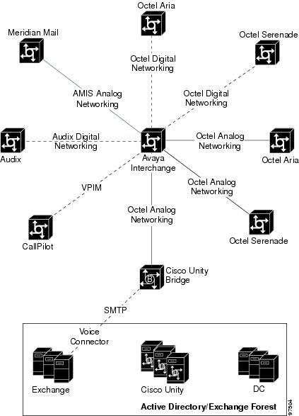
Figure 12-1 shows how the Cisco Unity Bridge allows the Cisco Unity network to send and receive voice messages with the rest of the voice messaging network via the Avaya Interchange.
Figure 12-1 Cisco Unity Bridge Communicates with the Avaya Interchange
It is not necessary for Cisco Unity to know which protocols are being used for communication between the Interchange and the other voice messaging systems. Similarly, it is not necessary for Cisco Unity to know the local mailboxes in use on each of the other voice messaging servers. The Avaya Interchange maintains an addressing table for the entire network in which it maps the local mailboxes for each voice messaging system to a network address. Therefore, Cisco Unity only needs to know the network addresses as configured on the Interchange for each of the other voice messaging systems in the network.
In essence, Cisco Unity and the Cisco Unity Bridge see the Avaya Interchange—and all voice messaging systems with which it communicates—as a single large Octel Analog Networking node, with a single Octel serial number, whose mailboxes are the entire list of network addresses accessible via the Interchange.
Likewise, the Avaya Interchange sees Cisco Unity and the Cisco Unity Bridge—including all subscribers on all Cisco Unity servers in the network—as one or more Octel Analog Networking nodes, with one or more Octel serial numbers. The number of different Octel Analog Networking nodes represented by the Cisco Unity network, and the mailboxes for each node, are defined within the Cisco Unity network by use of the Legacy Mailbox and Remote Node ID properties for each Cisco Unity subscriber, and by the Unity Node profiles configured on the Cisco Unity Bridge.
The network addressing configured on the Avaya Interchange, and for that matter most large voice messaging networking numbering plans, is typically configured to mirror the actual phone numbers used to contact the subscribers. This allows a single corporate directory to be used for phoning someone else in the company, and for sending the same person a network voice message. In most cases, a corporate-wide 7-digit or 10-digit numbering scheme is used.
Adding a Cisco Unity Network to an Existing Avaya Interchange Network
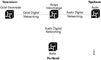
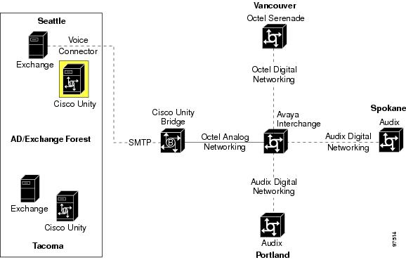
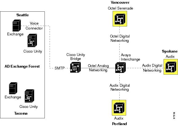
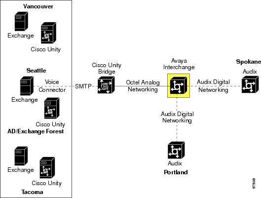
A fictional company, JB Enterprises, has offices in Portland, Spokane, and Vancouver. See Figure 12-2. The Portland and Spokane offices each have an Audix system for voice messaging. The Vancouver office has an Octel Serenade 200. An Avaya Interchange is used to allow network voice messaging between these three offices.
Figure 12-2 The Voice Messaging Network of JB Enterprises
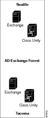
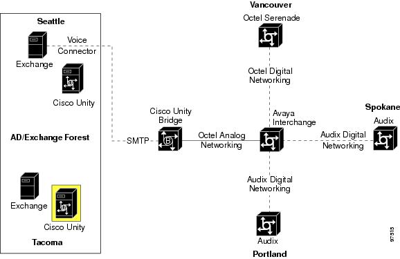
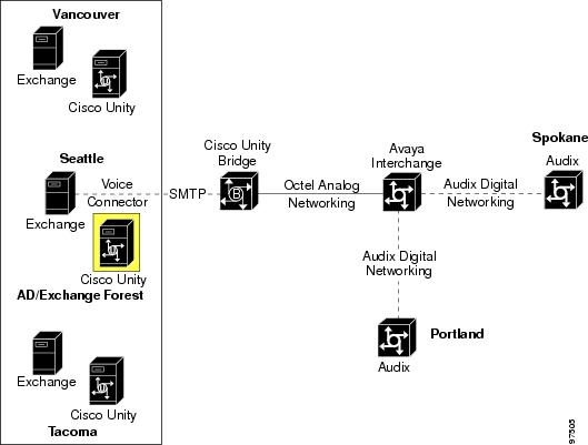
JB Enterprises has just acquired RT Inc., a company with offices in Seattle and Tacoma. As Figure 12-3 illustrates, the Seattle and Tacoma offices of RT Inc. each have a Cisco Unity voice messaging system, deployed in a single Exchange 2000 Active Directory network to allow network voice messaging between the two offices, by using Cisco Unity Digital Networking.
Figure 12-3 Newly Acquired Seattle and Tacoma Cisco Unity Network
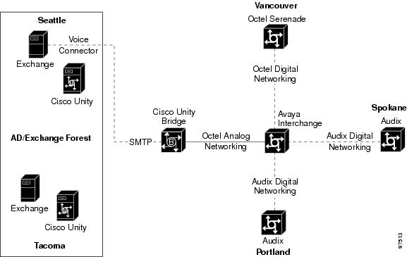
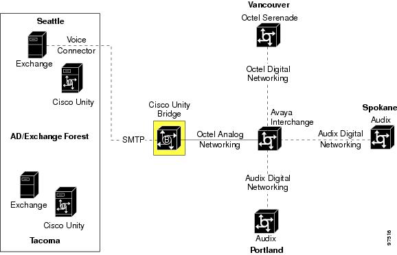
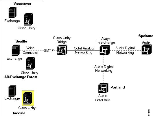
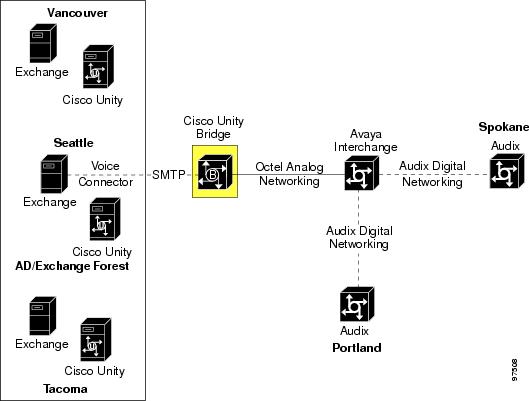
As Figure 12-4 illustrates, the Cisco Unity Bridge will be deployed in Seattle to communicate with the Avaya Interchange. This will allow employees to send network voice messages to and from any of the five locations.
Figure 12-4 The Cisco Unity Bridge Will Be Deployed in Seattle
Network Addressing Numbering Plan
Table 12-1 shows the phone numbers for employees at the three existing locations of JB Enterprises.
In order to mirror the network voice messaging addressing with the North American Numbering Plan (NANP) phone numbers, a 10-digit network addressing scheme is employed on the Interchange. By using 10 digits instead of 7, any conflicts that would occur with the common 215 CO prefix in Portland and Vancouver are avoided.
Table 12-2 shows what the dial plan mapping looks like on the Interchange.
When Portland subscriber 51000 sends a network voice message to 6042050000, the following occurs:
1.
2.
3.
4.
5.
6.
Table 12-3 shows the phone numbers for employees at the two new locations of JB Enterprises.
Table 12-3 Numbering Plan of New Locations
Seattle
206.214.xxxx
41000-43999
Seattle
206.215.xxxx
50000-50999
Tacoma
253.372.xxxx
21000-21999
Table 12-4 shows how the Interchange dial plan mapping will be updated when the Cisco Unity Bridge is deployed.
Configuration Steps
Only one Cisco Unity server needs to be configured for Bridge Networking. This server is known as the "bridgehead." JB Enterprises chose to configure the Seattle Cisco Unity server as the bridgehead.
JB Enterprises used the following steps to incorporate Cisco Unity into the Interchange voice messaging network by using the Cisco Unity Bridge.
1.
Figure 12-5 The Seattle Cisco Unity Is Configured as the Bridgehead
a.
b.
Global Directory
Global Directory
c.
Interchange
001
Bridge
bridge.rtinc.com
80000
10
d.
e.
f.
<same as primary extension>
80001
2.
Figure 12-6 The Tacoma Cisco Unity Server Is Configured for Messaging with the Cisco Unity Bridge
a.
Global Directory
Global Directory
b.
<same as primary extension>
80001
3.
Figure 12-7 The Cisco Unity Bridge Is Configured
a.
80001
Unity1
UnitySEA
rtinc.com
b.
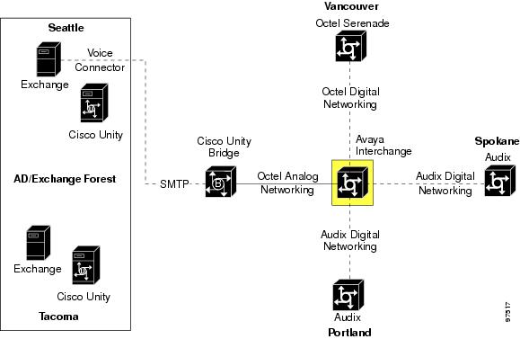
4.
Figure 12-8 The Interchange Is Configured
a.
b.
Cisco Unity
Octel Analog
<trunk access code + Cisco Unity Bridge phone number>
ARIA Analog
y
c.
Note
d.
e.
f.
g.
In order for Cisco Unity subscribers to receive messages from other subscribers in the Interchange network, the Cisco Unity subscriber mailboxes must be registered on the Avaya Interchange. There are a number of ways this can be done: by using Bulk Import, defining a mailbox range; by manual entry; by subscriber self-registration, and so on. Refer to the Avaya Interchange Administration Guide for detailed instructions.
5.
Figure 12-9 The Other Voice Messaging Systems in the Network Are Configured
a.
Configure the server to route the following network addresses to the Interchange: 2062141000 through 2062143999; 2062150000 through 2062150999; and 2533721000 through 2533721999.
b.
Configure the server to route the following network addresses to the Interchange: 2062141000 through 2062143999; 2062150000 through 2062150999; and 2533721000 through 2533721999.
c.
Configure the server to route the following network addresses to the Interchange: 2062141000 through 2062143999; 2062150000 through 2062150999; and 2533721000 through 2533721999.
Additional Network Addressing Notes
If JB Enterprises wanted to make network addressing even more consistent by having Seattle employees address Tacoma employees by using 10-digit addressing, and vice versa, this is simply accomplished by adding the 10-digit DID numbers for Seattle and Tacoma Cisco Unity subscribers as Alternate Extensions on their respective Cisco Unity servers. The alternate extensions, which are replicated to the global subscriber table, allow subscribers to address Seattle and Tacoma employees by using either the 5-digit primary or 10-digit alternate extensions from anywhere within the Cisco Unity network.
Pushing Mailbox Information from the Interchange to Cisco Unity
The Avaya Interchange may be configured to push mailbox information (text name and/or spoken name) to other systems via Octel analog networking; version 3.0(6) of the Bridge provides the capability to accept this mailbox information and use it to update the Bridge directory and the Bridge subscriber directory in Cisco Unity.
As in the example above, the directory view for Cisco Unity on the Interchange should be configured to include the mailbox ranges of all extensions for which mailbox updates will be pushed. For details on configuring the Bridge to accept remote push requests, see the "Enabling the Bridge to Accept Requests to Push Mailbox Information (Bridge 3.0(6) and Later)" section.
Note
Migrating a Location from the Interchange to Cisco Unity
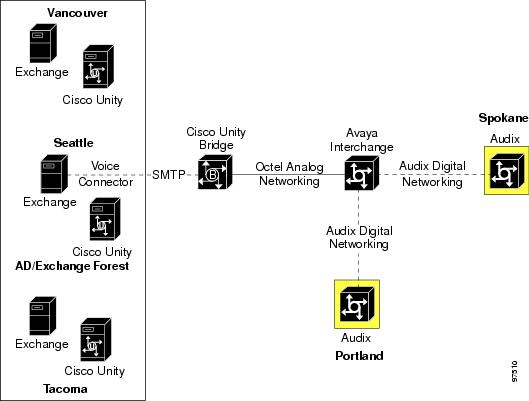
To take this example one step further, the next section describes the steps necessary to reconfigure the network when the Vancouver location migrates from Octel Serenade to Cisco Unity.
Vancouver has a mailbox range of 50000-50999, which is also a range in use in the Seattle location (see Table 12-2). JB Enterprises wants to continue to use the same 5-digit mailbox ranges in both Seattle and Vancouver, which is allowed because they are in different Cisco Unity Dialing Domains. In Cisco Unity 4.0(3) and later, (and when using the Cisco Unity Voice Connector 10.0(3) and later), this plan will work. In the new design, the Legacy Mailbox and Remote Node ID Unity subscriber properties are used for identifying Cisco Unity subscribers as senders or recipients of Bridge voice messages. So as long as each subscriber in the Cisco Unity network is configured with a unique combination of these two properties, the subscribers can maintain their existing primary mailbox extensions. In this case, the Vancouver Cisco Unity subscribers will be configured with a different Remote Node Id—80002—than the Cisco Unity subscribers in Seattle. The Cisco Unity Bridge will be configured accordingly, and the Interchange will treat the Cisco Unity network as though it were two separate Octel Analog Networking nodes, both of which will be represented by the same Cisco Unity Bridge server in Seattle.
Configuration Steps
1.
Figure 12-10 Additional Configuration for the Cisco Unity Bridgehead Server in Seattle
a.
b.
Global Directory
Global Directory
c.
Interchange
001
Bridge
bridge.rtinc.com
80000
10
d.
e.
f.
<same as primary extension>
80001
2.
Figure 12-11 Additional Configuration for the Tacoma Cisco Unity Server
a.
Global Directory
Global Directory
b.
<same as primary extension>
80001
3.
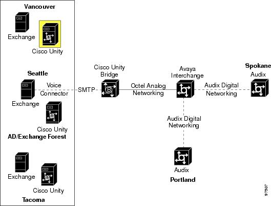
Figure 12-12 The Cisco Unity Server in Vancouver Is Configured
a.
Global Directory
Global Directory
b.
<same as primary extension>
80002
4.
Figure 12-13 The Cisco Unity Bridge Is Configured
a.
80001
Unity1
UnitySEA
rtinc.com
b.
80002
Unity2
UnitySEA
rtinc.com
c.
5.
Figure 12-14 The Configuration on the Interchange Is Updated
a.
Vancouver
Octel Analog
<trunk access code + Cisco Unity Bridge phone number>
Aria Analog
y
b.
Note
c.
d.
In order for Cisco Unity subscribers to receive messages from other subscribers in the Interchange network, the Cisco Unity subscriber mailboxes must be registered on the Avaya Interchange. There are a number of ways this can be done: by using Bulk Import, defining a mailbox range; by manual entry; by subscriber self-registration, and so on. Refer to the Avaya Interchange Administration Guide for detailed instructions.
6.
Figure 12-15 The Other Voice Messaging System Configuration Is Updated
There should be no need to edit the configuration on the remaining Portland and Spokane servers because they are already configured to route messages to Vancouver network addresses through the Interchange.
Additional Network Addressing Notes
If JB Enterprises wanted to make network addressing even more consistent, by having Seattle, Tacoma, and Vancouver employees address one another by using 10-digit addressing, this could easily be accomplished by adding the 10-digit DID numbers for Seattle, Tacoma, and Vancouver Cisco Unity subscribers as alternate extensions on the respective Cisco Unity servers. The alternate extensions are replicated to the global subscriber table, and they allow Seattle and Tacoma employees to be addressed either by using their 5-digit primary extensions, or their 10-digit alternate extensions from anywhere within the Cisco Unity network.