-
Cisco Unity Bridge Networking Guide, Release 3.0 (With Microsoft Exchange)
-
Index
-
Preface
-
About Bridge Networking
-
Setting Up Cisco Unity and the Bridge for Networking
-
Upgrading from Bridge 2.x to Bridge 3.x
-
Upgrading from Cisco Unity 4.0(3) or Later with Bridge 3.x
-
Monitoring and Maintaining Bridge Networking
-
Troubleshooting Bridge Networking
-
Advanced Troubleshooting Topics
-
Uninstalling Bridge Networking Components
-
Reference: Bridge Settings on the Cisco Unity Server
-
Reference: Settings on the Bridge Server
-
Primary Location Settings
-
Cisco Unity Bridge and Avaya Interchange
-
Glossary
-
 Feedback
Table Of Contents
Upgrading from Bridge 2.x to Bridge 3.x
Task List: Upgrading From Bridge 2.x to Bridge 3.x
Obtaining a License File for the Bridge Server
Downloading the Required Microsoft Service Packs
Obtaining the Serial Number of the Cisco Unity Bridgehead Server
Extending the Active Directory Schema
Upgrading Non-Bridgehead Cisco Unity Servers
Upgrading All Non-Bridgehead Cisco Unity Servers to 4.0(3) or Later
Adding the Serial Number and Mailbox ID to Cisco Unity Subscriber Accounts
Installing Microsoft Service Packs and Updates
Upgrading to Cisco Unity Bridge Version 3.x from 2.x
Installing the License File Wizard and the License File
Uninstalling the Cisco Unity Voice Connector
Setting Up the Voice Connector for Bridge Networking
Upgrading the Cisco Unity Bridgehead Server
Upgrading the Cisco Unity Bridgehead Server to 4.0(3) or Later
Designating the Bridgehead Server
Configuring the Cisco Unity Bridgehead Server
Configuring Bridge Delivery Locations
Synchronizing Cisco Unity Subscriber Data with the Bridge
Testing the Octel Analog Network
Installation with Multiple Cisco Unity Servers Networked via Digital Networking
Customizing the Primary Location
Setting the Automated Attendant Search Scope
Setting Permissions on Active Directory Containers Used for Importing Subscribers
Enabling Identified Subscriber Messaging
Extending Identified Subscriber Messaging
Enabling the Bridge Server to Send Extended-Absence Delivery Receipts (Cisco Unity 4.0(4) or Later)
Enabling the Bridge to Accept Requests to Push Mailbox Information (Bridge 3.0(6) and Later)
Upgrading from Bridge 2.x to Bridge 3.x
If you currently have Cisco Unity 3.1(3) through 4.0(2) servers configured for networking with Bridge 2.x server(s), use the task list and procedures in this chapter to upgrade the Cisco Unity server(s) to 4.0(3) or later, and the Bridge server(s) to 3.x.
The design of the Bridge Networking option changed significantly beginning with Cisco Unity 4.0(3) with Bridge 3.0(1). Bridge Networking now provides many new features. (See the "New and Changed Functionality in Cisco Unity 4.0(3) and Later with Cisco Unity Bridge 3.x" section on page 1-6, the "New and Changed Functionality—Cisco Unity 4.0(4)" section on page 1-3, and the "New and Changed Functionality—Cisco Unity 4.0(5)" section on page 1-2 for details.) To take advantage of these new features:
•
All Cisco Unity servers in the Cisco Unity network must be upgraded to version 4.0(3) or later.
•
•
•
If it is not possible to upgrade all affected servers simultaneously, the following task list describes the most effective way to upgrade in steps. When you follow these steps, messaging between Cisco Unity and Octel subscribers will not be interrupted except for a small period of time during the upgrade. Note that the new features will not be available until the entire upgrade is complete.
Task List: Upgrading From Bridge 2.x to Bridge 3.x
Prepare for the Upgrade
1.
2.
–
–
3.
4.
Extend the Active Directory Schema
5.
Upgrade Non-Bridgehead Cisco Unity Servers
Networking with the Octel servers is not disrupted when upgrading non-bridgehead Cisco Unity servers. Subscribers on the newly upgraded Cisco Unity servers can still send and receive Bridge messages as before, and therefore you can upgrade the non-bridgehead servers as your schedule permits.
6.
–
–
7.
Time-Critical Final Tasks
The remaining tasks in this list are related to upgrading the Bridge server, the Voice Connector(s), and the Cisco Unity bridgehead server. Plan ahead to do these tasks after normal business hours, or when voice message delivery between Cisco Unity and Octel subscribers is least critical.
Upgrade the Bridge Server
8.
9.
10.
11.
Upgrade the Voice Connector
12.
13.
Upgrade the Cisco Unity Bridgehead Server
14.
–
–
15.
16.
Configure the Cisco Unity Bridgehead Server
17.
18.
19.
Test the Setup
20.
21.
Enable Optional Features
22.
23.
24.
Preparing for the Upgrade
Obtaining a License File for the Bridge Server
In Cisco Unity 4.0(3) and later with Bridge 3.0(1) and later, a license file is required for the Bridge server. In previous versions, a license file with Bridge ports enabled was required for the Cisco Unity server configured for Bridge Networking (referred to as the bridgehead server). As of Cisco Unity 4.0(3), a license file with Bridge ports enabled is not required on the Cisco Unity bridgehead server.
You obtain the license file for the Bridge server by completing registration information on Cisco.com. Shortly after registration, Cisco e-mails the license file. The e-mail from Cisco contains instructions on how to save and store the file. Specific instructions for installing the license file are provided later in this chapter.
The following information is required during registration:
•
•
Do the following two procedures in the order listed.
To Get the MAC Address of the Bridge Server
Step 1
Step 2
Step 3
If the server contains more than one NIC, one value will appear for each NIC. Use the value for the primary NIC.
Step 4
To Register and Obtain the License File
Step 1
Step 2
Step 3
Step 4
If license files are lost, it can take up to one business day to get another copy.
If you do not receive the license files within 1 hour, or to get another copy of a license file, call the Cisco Technical Assistance Center (TAC) and ask for the Licensing Team:
800 553-2447
the U.S.For your local Cisco TAC phone number, refer to the website http://www.cisco.com/warp/public/687/Directory/DirTAC.shtml.
Or send e-mail to licensing@cisco.com.
You will need to provide information to verify Bridge ownership—for example, the purchase order number or the PAK (which appears on the sticker located on the front of the sleeve for the Cisco Unity Bridge CD).
Downloading the Required Microsoft Service Packs
If the Bridge server does not already have the required Microsoft service packs, refer to the "Downloading the Software for a Cisco Unity Bridge Installation or Upgrade" section of the Release Notes for Cisco Unity Bridge, available at http://www.cisco.com/univercd/cc/td/doc/product/voice/c_unity/bridge30/relnote/index.htm.
The instructions for installing the service packs from the download file CiscoUnity4.0-ServicePacks-ENU-CD1.exe can be found in the "Upgrading the Bridge Server" section.
Caution
Obtaining the Serial Number of the Cisco Unity Bridgehead Server
To Obtain the Serial Number of the Cisco Unity Bridgehead Server
Step 1
Step 2
Extending the Active Directory Schema
Before Cisco Unity is installed, the Active Directory schema is extended to store some information specific to Cisco Unity. However, to support Bridge Networking, the schema must be further extended. Bridge 3.x with Cisco Unity 4.0(3) or later requires schema extensions in addition to those required by Bridge 2.x.
To Extend the Active Directory Schema for Bridge Networking
A log file is generated each time the schema is updated. A shortcut to the directory where the log file is located is placed on the Windows desktop. To see the changes that the schema update program makes, browse to the directory Schema\LdifScripts on Cisco Unity Disc 1, and view the file omnigateway.ldf.
Step 1
Step 2
Step 3
Step 4
Step 5
Step 6
Step 7
Step 8
Note
Upgrading Non-Bridgehead Cisco Unity Servers
Upgrading All Non-Bridgehead Cisco Unity Servers to 4.0(3) or Later
Upgrade all non-bridgehead Cisco Unity servers in the network to 4.0(3) or later. Do not upgrade the Cisco Unity server designated as the bridgehead at this time. For systems that use failover, upgrade the secondary servers as well (except for the bridgehead secondary server).
•
•
Adding the Serial Number and Mailbox ID to Cisco Unity Subscriber Accounts
In order for Cisco Unity subscribers to be able to send messages to and receive messages from subscribers on the Octel nodes with which Cisco Unity communicates, each Cisco Unity subscriber account must be configured with a serial number and mailbox ID. When upgrading a Cisco Unity network where the Bridge feature is already in use, for the existing Cisco Unity subscribers, we recommend:
•
•
Note
You can manually add the serial number and mailbox ID to existing subscriber accounts one at a time by using the Cisco Unity Administrator, or you can do so in bulk by using the Subscriber Information Dump and the Cisco Unity Bulk Import wizard, as described in the following procedure.
To Add the Octel Serial Number and Mailbox ID to Existing Cisco Unity Subscriber Accounts
Step 1
Step 2
Step 3
Step 4
Step 5
Step 6
Step 7
Step 8
Cisco Unity 4.0(3) with SR1, 4.0(4), and later: Check the Alias and Primary Extension check boxes in the Data to Include in Output File list.
Step 9
When the output is complete, a message box opens with the number of errors encountered in the process. Click OK to view the error log, or Cancel if no errors were encountered.
Step 10
Step 11
Caution
Step 12
Step 13
Step 14
Step 15
ALIAS,LEGACY_MAILBOX,REMOTE_NODE_ID
aabade,2001,55115
kbader,2002,55115
tcampbell,2003,55115
lcho,2004,55115Step 16
Step 17
Step 18
Step 19
Step 20
Step 21
Step 22
Step 23
Step 24
Step 25
If the alternate extensions for the subscribers were deleted, do the following sub-steps to add them back:
a.
b.
c.
d.
Step 26
Upgrading the Bridge Server
Disabling the Fax Service
Disable the Windows fax service to prevent it from interfering with Brooktrout software.
To Disable the Windows Fax Service
Step 1
Step 2
Step 3
Step 4
Step 5
Step 6
Installing Microsoft Service Packs and Updates
If the Bridge server does not have the required Microsoft service packs, do the following procedures in this section:
•
•
•
•
To Install Internet Explorer 6 with Service Pack 1
Step 1
Step 2
To Install MSXML 3.0 with Service Pack 1
Step 1
Step 2
To Install Windows 2000 Server Service Pack 4
Step 1
Step 2
Step 3
To Install the Latest Microsoft Updates
Step 1
Step 2
•
•
•
For more detailed information, refer to Microsoft Knowledge Base article 296861, How to Install Multiple Windows Updates or Hot Fixes with Only One Reboot.
Step 3
Step 4
Upgrading to Cisco Unity Bridge Version 3.x from 2.x
We recommend that you upgrade when Bridge message traffic is light. To upgrade to Bridge 3.x from Bridge 2.x:
1.
2.
3.
To Disable and Stop Virus-Scanning and Cisco Security Agent Services
Step 1
Step 2
Step 3
a.
b.
c.
d.
Step 4
To Upgrade to Cisco Unity Bridge Version 3.0 from 2.x
Step 1
Step 2
a.
b.
Caution
Step 3
•
•
The Bridge services will complete the shutdown process when the last in-process message transmission or reception, rather than call, is complete. No additional message transmissions will begin on the in-process calls—either outbound or inbound—after shutdown has been initiated.
Step 4
Otherwise, insert the Cisco Unity Bridge compact disc in the CD-ROM drive, and browse to the Install directory.
Step 5
Step 6
Step 7
Step 8
Step 9
Step 10
Step 11
Step 12
To Re-enable and Start Virus-Scanning and Cisco Security Agent Services
Step 1
Step 2
Step 3
a.
b.
c.
d.
Step 4
Installing the License File Wizard and the License File
Note that after installing the license file, you will need to restart the Unity Bridge service.
To Install the License File Wizard and the License File
Step 1
Step 2
Step 3
Step 4
To Restart the Unity Bridge Service
Step 1
Step 2
Step 3
Upgrading the Voice Connector
Uninstalling the Cisco Unity Voice Connector
The uninstall procedure that you use depends on the Cisco Unity Voice Connector version that is in use. Beginning with Cisco Unity version 4.0(1), the Voice Connector was assigned a version number separate from the Cisco Unity version number. Table 3-1 lists the Voice Connector versions and the Cisco Unity versions that they shipped with.
Use the following procedures to determine which version of the Voice Connector is in use:
•
Use the following procedures to uninstall the Voice Connector:
•
To Determine the Voice Connector Version in Use (Cisco Unity 3.1(6) and Later, Voice Connector 10.0 and Later)
Step 1
Step 2
or Exchange 2003<ExchangeServerPath>\VoiceGateway\Bin
<ExchangeServerPath>\Connect\Voice\Bin
Step 3
Step 4
Step 5
To Determine the Voice Connector Version in Use (Cisco Unity 3.0 through 3.1(5) Only)
Step 1
Step 2
<ExchangeServerPath>\VoiceGateway\Bin\LocalizedFiles\ENU
<ExchangeServerPath>\Voice\Bin\LocalizedFiles\ENU
Step 3
Step 4
To Uninstall the Voice Connector for Exchange 2000 (Cisco Unity 3.1 and Later, Voice Connector 10.0 and Later)
Step 1
Step 2
Step 3
Step 4
Step 5
Step 6
The mailbox for the Voice Connector is named "AvExchangeIVC_<Servername>" or "Exchange 2000 Voice Connector (<Servername>)."
Step 7
Step 8
Step 9
To Uninstall the Voice Connector for Exchange 2000 (Cisco Unity 3.0)
Step 1
Step 2
Step 3
Step 4
Step 5
Step 6
Step 7
The mailboxes are listed in the right pane. The mailbox name for the Voice Connector is AvExchangeIVC.
Step 8
Step 9
Step 10
Setting Up the Voice Connector for Bridge Networking
Although there are two Voice Connector installation programs included with Cisco Unity, the Voice Connector for Exchange 2000 is the only one supported for messaging with the Bridge.
Install the Voice Connector on any Exchange 2000 or Exchange 2003 server that is not part of an Exchange cluster (Microsoft does not support third-party connectors on an Exchange cluster server). Although the Voice Connector can be installed on the Cisco Unity server (when Exchange is also on the server), this is not recommended for performance reasons.
If the Exchange server on which the Voice Connector will be installed is in a different routing group than the Exchange servers on which Cisco Unity subscribers are homed, routing group connectors must be configured between the routing groups.
The Voice Connector service is automatically configured to log on as the LocalSystem account. The account that the service logs on as should not be changed.
The Voice Connector installation program does not prompt with a choice of languages for the installation; it always installs in English. To run the Voice Connector installation program by using one of the localized versions (FRA, DEU, or JPN) instead of English, see the "Running the Voice Connector Setup Program in Another Language" section on page 1-35.
To Install the Voice Connector for Exchange 2000
As a best practice, back up the Exchange server before installing the Voice Connector.
Step 1
Step 2
Step 3
Step 4
If you downloaded the Voice Connector files from the Software Center website, browse to the directory in which the files were extracted.
Step 5
Step 6
Step 7
Step 8
Step 9
To Determine Whether the Microsoft Windows 2000 Script Host Should Be Updated
In order to view Voice Connector properties in Exchange System Manager, Microsoft Windows Script Host version 5.6 or later must be installed on the Exchange server. If the Exchange server uses an earlier version of Windows Script Host, the Voice Connector will function properly, but you will not be able to view Voice Connector properties in the Exchange System Manager.
Do the following procedure to determine the version of Microsoft Windows 2000 Script Host.
Step 1
Step 2
Step 3
Step 4
Step 5
To Verify the Voice Connector Installation
To verify that the Voice Connector for Exchange 2000 installed properly, verify that the Voice Connector service is running, and that the Voice Connector mailbox has been created.
Step 1
Step 2
Step 3
Step 4
Step 5
Step 6
Step 7
In the right pane, you should see the mailbox for "Exchange 2000 Voice Connector (<Server name>)" or "AvExchangeIVC_<Server name>." (The name changes from "AvExchangeIVC_<Server name>" to "Exchange 2000 Voice Connector (<Server name>)" after you run Cleanup Agent.)
Step 8
Upgrading the Cisco Unity Bridgehead Server
Upgrading the Cisco Unity Bridgehead Server to 4.0(3) or Later
Upgrade the Cisco Unity bridgehead server to 4.0(3) or later. For systems that use failover, upgrade the secondary server as well.
•
•
Designating the Bridgehead Server
In versions of Cisco Unity prior to 4.0(3), the presence of a license file with Bridge ports enabled was necessary in designating a Cisco Unity server as the bridgehead. In Cisco Unity 4.0(3) and later, a license file with Bridge ports enabled is no longer required on the Cisco Unity bridgehead server.
To designate a Cisco Unity 4.0(3) or later server as a bridgehead, you run the ConfigMgr.exe utility with the Create Bridge Account option. ConfigMgr.exe installs and configures components required by the bridgehead server, as follows:
•
•
•
•
•
•
To Designate the Bridgehead Server
Step 1
Step 2
Step 3
Step 4
Step 5
Adding the Serial Number and Mailbox ID to Cisco Unity Subscriber Accounts Homed on the Bridgehead Server
In order for Cisco Unity subscribers to be able to send messages to and receive messages from subscribers on the Octel nodes with which Cisco Unity communicates, each Cisco Unity subscriber account must be configured with an serial number and mailbox ID. For existing Cisco Unity subscribers, we recommend:
•
•
You can manually add the serial number and mailbox ID to existing subscriber accounts one at a time by using the Cisco Unity Administrator, or you can do so in bulk by using the Subscriber Information Dump and the Cisco Unity Bulk Import wizard, as described in the following procedure.
To Add the Octel Serial Number and Mailbox ID to Existing Cisco Unity Subscriber Accounts
Step 1
Step 2
Step 3
Step 4
Step 5
Step 6
Step 7
Step 8
Cisco Unity 4.0(3) with SR1, 4.0(4), and later: Check the Alias and Primary Extension check boxes in the Data to Include in Output File list.
Step 9
When the output is complete, a message box opens with the number of errors encountered in the process. Click OK to view the error log, or Cancel if no errors were encountered.
Step 10
Step 11
Caution
Step 12
Step 13
Step 14
Step 15
ALIAS,LEGACY_MAILBOX,REMOTE_NODE_ID
aabade,2001,55115
kbader,2002,55115
tcampbell,2003,55115
lcho,2004,55115Step 16
Step 17
Step 18
Step 19
Step 20
Step 21
Step 22
Step 23
Step 24
Step 25
If the alternate extensions for the subscribers were deleted, do the following sub-steps to add them back:
a.
b.
c.
d.
Step 26
Configuring the Cisco Unity Bridgehead Server
Configuring Bridge Delivery Locations
In Cisco Unity 4.0(3) and later, there are new Bridge delivery location pages and new settings on the delivery location profile page. Configure these new settings on each Bridge delivery location, as applicable.
For more information about the settings, see the following sections:
•
•
•
To Configure Bridge Delivery Locations
Step 1
Step 2
Step 3
Step 4
Configuring Bridge Options
For more information about the Bridge Options, see the following sections:
•
•
To Configure Bridge Options
Step 1
Step 2
Synchronizing Cisco Unity Subscriber Data with the Bridge
To Synchronize Cisco Unity Subscriber Data with the Bridge
Step 1
Step 2
Step 3
Testing the Octel Analog Network
Before sending test messages between Cisco Unity and the Octel(s), as a best practice, first verify that the Bridge can communicate with each of the configured Octel nodes. Testing the Octel analog network separately allows you to more quickly identify and fix any problems that you may encounter. To do the tests, you will use the Bridge Analog Network And Node Analyzer (BANANA).
BANANA is a stand-alone application that runs on the Bridge server. It is designed to assist with monitoring and troubleshooting analog communication between the Bridge and the Octel nodes in the analog network. It also provides detail and summary information of call activity.
BANANA contains an administration application called the BANANA admin that allows you to control how BANANA:
•
•
•
With the BANANA admin, you can also install and configure the BANANA service to do the tasks listed above at configurable intervals.
Caution
The following procedures provide details for installing and initiating test calls. Refer to the BANANA Help file for information about other functionality provided by BANANA.
To Install BANANA
Step 1
Step 2
Step 3
Step 4
Step 5
Step 6
Step 7
Step 8
Step 9
Step 10
Step 11
Note
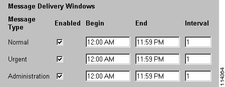
To Adjust the Message Delivery Window Settings
Step 1
Step 2
Step 3
Note that BANANA makes only administrative calls when testing the Octel analog network. However, if you adjust the normal and urgent schedules as shown, you do not have to remember to adjust the schedule if you also send test messages from Cisco Unity subscribers to Octel subscribers.
Step 4
Step 5
To Initiate Test Calls to the Octel Nodes
Step 1
Step 2
Step 3
Step 4
Step 5
Refer to the BANANA Help for details.
Testing the Setup
Before beginning this procedure, create test subscriber accounts on Cisco Unity and on each Octel node for which a delivery location has been configured. Be sure to record voice names for the subscribers. See the "Creating New or Modifying Existing Subscriber Accounts for Testing Purposes" section on page 2-15 for instructions.
To Test the Setup
Step 1
Step 2
Step 3
Step 4
a.
b.
Step 5
a.
b.
c.
d.
Step 6
Extending Identified Subscriber Messaging to Include Bridge Subscribers (Cisco Unity 4.0(4) or Later)
If all of your Cisco Unity servers are running version 4.0(4) or later, you can extend identified subscriber to include Bridge subscribers.
When a person on a remote voice messaging system who has a corresponding Bridge subscriber account calls a Cisco Unity subscriber and leaves a message, by default Cisco Unity will not identify the message as being from the Bridge subscriber. For Cisco Unity to identify callers whose calling number matches the extension or alternate extension of an External subscriber, identified subscriber messaging (ISM) must be extended to include Bridge subscribers. See the following sections as applicable to your installation.
•
Installation with Multiple Cisco Unity Servers Networked via Digital Networking
In installations with multiple Cisco Unity servers networked via Digital Networking, enabling ISM to include Bridge subscribers requires the following:
1.
2.
3.
4.
5.
6.
Single-Server Installations
In installations with only one Cisco Unity server, enabling ISM to include Bridge subscribers requires the following:
1.
2.
3.
4.
Customizing the Primary Location
If your installation consists of multiple Cisco Unity servers networked via Digital Networking, you may have already customized the primary location.
For detailed information about the settings, see the "Primary Location Profile Settings" section on page 11-1.
To Customize the Primary Location
Step 1
Step 2
Step 3
Step 4
Step 5
•
•
Note that the dialing domain name is case sensitive and must be entered exactly the same on all of the servers. To ensure that all servers are correctly added to the same dialing domain, enter the dialing domain name on one Cisco Unity server and wait for the name to replicate to the other Cisco Unity servers. By doing so, you also confirm that replication is working correctly among the servers. The time that it takes for the primary location data from other Cisco Unity servers to be reflected on the local server depends on your network configuration and replication schedule.
Step 6
Setting the Automated Attendant Search Scope
If your installation consists of multiple Cisco Unity servers networked via Digital Networking, the automated attendant search scope must be set.
To Set the Automated Attendant Search Scope
Step 1
Step 2
Step 3
Step 4
Step 5
You do not need to restart Cisco Unity to enable the change.
Step 6
Setting Permissions on Active Directory Containers Used for Importing Subscribers
If you will be importing contacts from two or more containers (for all of the Cisco Unity servers combined), the Cisco Unity message store services account on each Cisco Unity server must be granted SendAs permission on every container from which contacts will be imported on every Cisco Unity server in the forest. Otherwise, identified subscriber messaging may not work between Cisco Unity servers. For example, if CiscoUnityServer1 will import contacts from Container1 and Container2, and if CiscoUnityServer2 will import contacts from Container3 and Container4, Cisco Unity message store services account on each Cisco Unity server must have SendAs permission for all four containers.
To Set the Appropriate Permissions
Step 1
Step 2
Step 3
Step 4
•
–
–
•
–
–
•
–
–
Step 5
Enabling Identified Subscriber Messaging
Note
To Enable Identified Subscriber Messaging
Step 1
Step 2
Identified subscriber messaging for subscribers on the same Cisco Unity server is enabled when the check box is unchecked. By default, the box is unchecked.
Step 3
Extending Identified Subscriber Messaging
After identified subscriber messaging has been enabled, you must extended it to include Bridge subscribers.
To Extend Identified Messaging
Step 1
Step 2
Step 3
Step 4
Step 5
Step 6
Step 7
Enabling the Bridge Server to Send Extended-Absence Delivery Receipts (Cisco Unity 4.0(4) or Later)
For Cisco Unity subscribers to receive delivery receipts, when the extended-absence greeting for an Octel subscriber is enabled and the mailbox is accepting messages, you need to modify a configuration setting on the Bridge server. See one of the following procedures as applicable for your version of the Bridge:
To Enable the Bridge to Send Extended-Absence Delivery Receipts (Cisco Unity 4.0(4) or Later with Cisco Unity Bridge 3.0(6))
Step 1
Step 2
Step 3
To Enable the Bridge to Send Extended-Absence Delivery Receipts (Cisco Unity 4.0(4) or Later with Cisco Unity Bridge 3.0(5))
Step 1
Step 2
Step 3
[config]
POP3_SERVER_ID=
ESMTP_SERVER_ID=
InetRecvProtocol=1
POP3_POLL_INTERVAL_MS=600000
OUTDIAL_INTERVAL_MS=600000
CALLX_IN_POLL_INTERVAL_MS=30000
PROXY_MAILBOX_MESSAGE=IMCEAOMNI-AvVoiceMessage
PROXY_MAILBOX_DIRECTORY=IMCEAOMNI-AvVoiceAddress
EnableExtAbsenceNotifications=0
SMTP_PORT=25Step 4
Step 5
Step 6
a.
b.
c.
Enabling the Bridge to Accept Requests to Push Mailbox Information (Bridge 3.0(6) and Later)
Some remote systems provide the capability to push name information to other nodes; version 3.0(6) of the Bridge provides the capability to accept this mailbox information and use it to update the Bridge directory and the Bridge subscriber directory in Cisco Unity.
By default, the Bridge will reject an attempt by the remote node to push mailbox information (but the call will proceed and the remote node will be able to continue with any additional tasks). When the accept remote push functionality is enabled, the Bridge will accept all administrative name push requests from any remote node, and will process the directory information even if the recorded voice name is not included in the transmission. If the mailbox information sent by the remote node does not match any existing mailbox in the Bridge directory, a new usage-based entry is added to the directory. If the information pertains to a mailbox that already exists in the Bridge directory, the Bridge will modify the directory entry; if the text name is blank or no recorded name is transmitted, the corresponding field will be removed from the directory entry.
Note
To Enable the Bridge to Accept Requests to Push Mailbox Information
Step 1
Step 2
Step 3