Feedback
Table Of Contents
Configuring CTRS Administration Software
Logging in to the Administrative User Interface
Left Menu of the Administrative User Interface
Creating a New User or Modifying Settings for an Existing User
Configuring Multiple Domains in an LDAP Forest
Configuring CTRS Administration Software
Revised: November 2009The following sections describe settings in the System Configuration screens for the Cisco TelePresence Recording Server (CTRS). System Configuration is divided into the following areas:
•
Logging in to the Administrative User Interface
•
Logging in to the Administrative User Interface
To log in to the CTRS administrative user interface, do the following:
Step 1
Step 2
Note
Step 3
For more information about the initial installation of CTRS, including setting the administrator username and password for the first time, see Chapter 3, "Installing CTRS Administration Software."
System Information
Click System Information in the left menu to view information about the CTRS. The information displayed under System Information is configured during CTRS software installation.
•
•
•
•
•
•
•
•
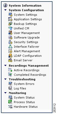
Left Menu of the Administrative User Interface
You can access any of the System Configuration screens from the left menu in the CTRS user interface (see Figure 4-1):
Figure 4-1 System Configuration—Left Menu
System Settings
System Settings are initially configured during CTRS Administration software set up. Use the System Settings to make changes to these initial settings. System Settings consists of the following configuration areas:
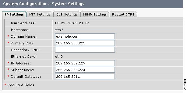
IP Settings
In System Settings, click the IP Settings tab to display or configure IP settings (see Figure 4-2).
Figure 4-2 System Configuration > System Settings—IP Settings
Some of the settings displayed on the IP Settings screen are configured during initial installation of the CTRS administration software. The following fields are configurable on this screen:
•
•
•
•
•
•
•
•
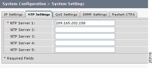
NTP Settings
In System Settings, click the NTP Settings tab to display or configure Network Time Protocol (NTP) servers (see Figure 4-3).
Figure 4-3 System Configuration > System Settings—NTP Settings
NTP is used to synchronize the clocks on Cisco IP telephony servers with an external network time server that uses NTP.
Click the NTP Setting tab in the System Settings window to list the configured IP address of the NTP servers.
•
•
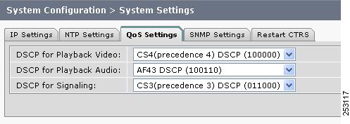
QoS Settings
In System Settings, click the QoS Settings tab to display or configure quality of service (QoS) settings (see Figure 4-4).
Figure 4-4 System Configuration > System Settings—QoS Settings
QoS values define the traffic marking values used for network queuing for CTRS. Enter or edit settings as described in Table 4-3.
•
•
SNMP Settings
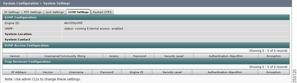
In System Settings, click the SNMP Settings tab to display or configure Simple Network Management Protocol (SNMP) settings (see Figure 4-5).
Figure 4-5 System Configuration > System Settings—SNMP Settings
The Simple Network Management Protocol (SNMP) is an application layer protocol that facilitates the exchange of management information between network devices. It enables network administrators to manage network performance, find and solve network problems, and plan for network growth by analyzing information gathered using MIBs. You configure all SNMP settings through the CTRS command line interface (CLI) commands.
SNMP is enabled by default, and it monitors the CTRS system status (go to Monitoring > System Status for system status details). You can designate a particular server where SNMP trap messages are gathered and stored. Configuration requires username and password authentication.
By default, SNMP service is enabled. The following default SNMP settings are also enabled:
•
•
•
Table 4-4 describes the SNMP fields. All fields in this screen are view-only.
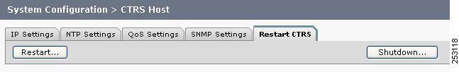
Restart or Shutdown CTRS
In System Settings, click the Restart CTRS tab to restart or to shut down the CTRS (see Figure 4-6).
Figure 4-6 System Configuration > System Settings—Restart CTRS
To restart CTRS:
Step 1
Step 2
Step 3
To shutdown CTRS:
Step 1
Step 2
Step 3
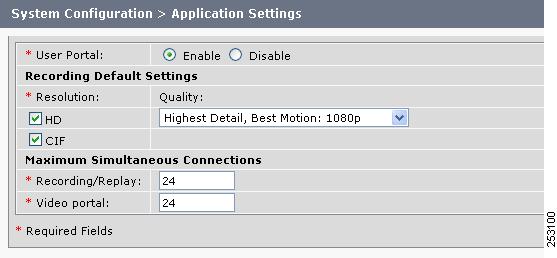
Application Settings
Click Application Settings in the left menu to display or modify application settings (see Figure 4-7).
Figure 4-7 System Configuration > Application Settings
Application Settings allow you to define general CTRS recording settings (see Table 4-5).
•
•
Backup Settings
Backup Settings consist of the following tabs:
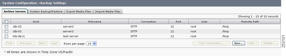
Archive Servers
In Backup Settings, click the Archive Servers tab to display or configure archive servers (see Figure 4-8).
Figure 4-8 System Configuration > Backup Settings—Archive Servers
The Archive Servers screen displays a table providing the following information about previously defined archive servers:
•
•
•
•
•
•
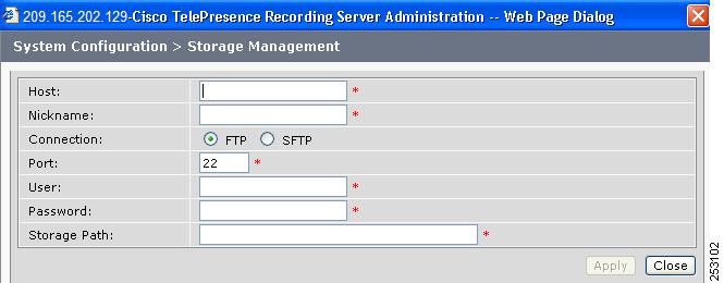
Figure 4-9 System Configuration > Backup Settings—Archive Servers (New or Edit)
When you click Edit or New, CTRS administration software takes you to the Storage Management screen, as described in Table 4-7. Use this screen to edit existing archive server settings or to define new archive servers.
•
•
System Backup and Restore
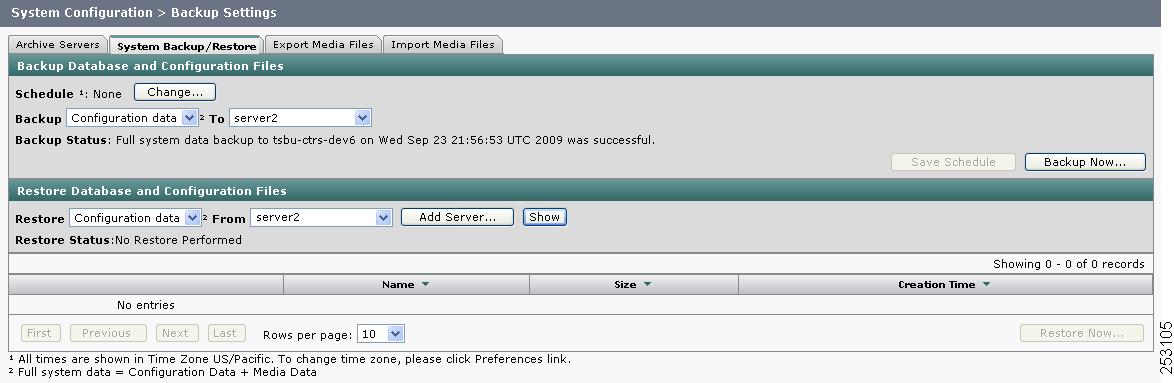
In Backup Settings, click the System Backup/Restore tab to display or configure settings for backup or system restoration (see Figure 4-10). From this screen, you can also perform a system backup or restoration.
Figure 4-10 System Configuration > Backup Settings—System Backup/Restore
The System Backup and Restore window is divided into two sections:
•
•
To schedule a system backup:
Step 1
a.
b.
c.
Step 2
Step 3
Step 4
Note
To perform an immediate system backup:
•
Backup database fields are described in Table 4-8.
To restore the CTRS database:
Step 1
Step 2
Step 3
•
•
Step 4
Step 5
Restore task fields are described in Table 4-9.
Export Media Files
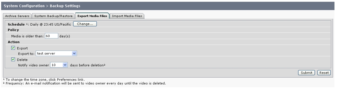
In Backup Settings, click the Export Media Files tab to display or configure settings to export media files (see Figure 4-11).
Figure 4-11 System Configuration > Backup Settings—Export Media Files
Use the Export Media Files screen to configure when CTRS transfers CTRS media data to a specified archive server. Export Media Files fields are described in Table 4-10.
•
•
For example, in the Schedule field, you click the Change button. For Start Time, you choose 23:45, and for Frequency, you choose Daily. In the Media is older than field, you enter 60. As the Action to be taken daily at 23:45, you check the Export box and specify a server to which the CTRS will export videos that are older than 60 days. You also check Delete, and in the Notify video owner field, you enter 10.
With this configuration, daily at 23:45, CTRS exports each video that is older than 60 days to the specified server. CTRS also marks for deletion each video that it exported. For the next ten days, CTRS marks the status of the video as "Delete Pending" (CTRS displays the status of each video in the list in Recordings Management > Completed Recordings). CTRS also sends an e-mail notification to the video owner to alert the owner of the upcoming deletion. This notification is sent every day for ten days. At the end of the ten-day period, the video is deleted from CTRS.
Import Media Files
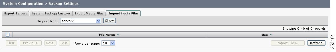
In Backup Settings, click the Import Media Files tab to display or configure settings to import media files (see Figure 4-12).
Figure 4-12 System Configuration > Backup Settings—Import Media Files
The Import Media Files screen lets you choose data files from a list of defined archive servers to be imported into the CTRS database.
To import media files:
Step 1
Step 2
•
•
•
Step 3
Step 4
Unified CM Settings
Cisco Unified Communications Manager Settings (Cisco Unified CM) consists of two configuration areas:
Cisco Unified CM Settings
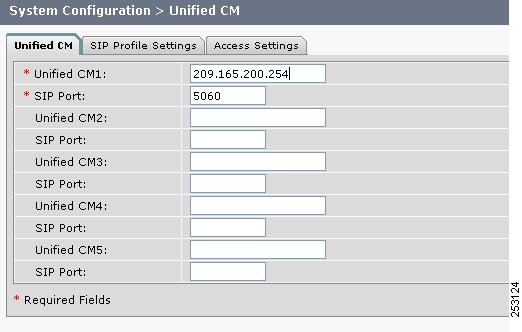
In Unified CM, click the Unified CM tab to display or configure Cisco Unified CM servers and SIP ports (see Figure 4-13).
Figure 4-13 System Configuration > Unified CM—Unified CM
From the Unified CM tab, you can specify Cisco Unified Communications Manager servers and SIP ports (see Table 4-11).
•
•
SIP Profile Settings
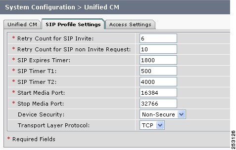
In Unified CM, click the SIP Profile Settings tab to display or configure SIP profile settings (see Figure 4-14).
Figure 4-14 System Configuration > Unified CM—SIP Profile Settings
SIP profile settings, which are described in Table 4-12, are applied to all SIP ports that you specify in the Unified CM tab.
•
•
Access Settings
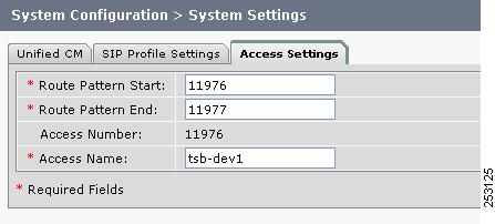
In Unified CM, click the Access Settings tab to display or configure route patterns or access settings (see Figure 4-15).
Figure 4-15 System Configuration > Unified CM—Access Settings
All of the settings on the Access Settings screen are derived from settings you configured in Cisco Unified Communications Manager (Cisco Unified CM).
•
•
User Management
Use the fields under User Management to define CTRS administrators and to provide access to the user portal. User Management is divided into two tabs:
Administrative Portal
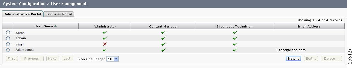
In User Management, click the Administrative Portal tab to display or configure CTRS administrative roles (see Figure 4-16).
Figure 4-16 System Configuration > User Management—Administrative Portal
Access to task menus within CTRS Administrative software is dependent on defined administrative roles. CTRS administration software recognizes three different administrative roles:
•
•
•
Administrative Portal initially displays a table providing the following information about already-defined administrative users as described in Table 4-14:
•
•
•
•
•
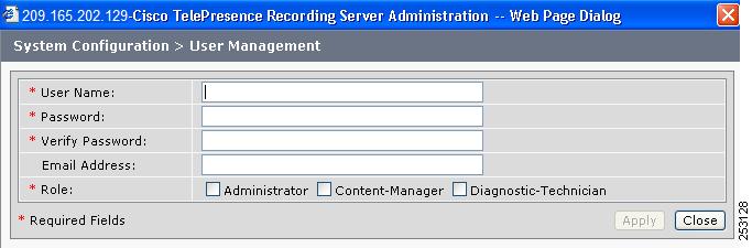
Creating a New Administrative User
When you click New, a dialog box appears (see Figure 4-17).
Figure 4-17 System Configuration > User Management—Administrative Portal (New)
Enter settings as described in Table 4-15.
•
•
Note
Editing a Defined Administrative User
When you click the radio button for a particular administrative user and then click Edit, a dialog box appears. Enter settings as described in Table 4-16.
•
•
End-User Portal
Note
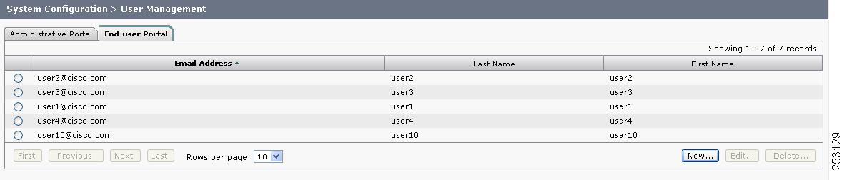
In User Management, click the End-user Portal tab to display or configure users of the user portal (see Figure 4-18).
Figure 4-18 System Configuration > User Management—End-user Portal
When you click the End-user Portal tab, you see a list of users with access to the CTRS user portal on an IP phone or through a web browser. Through the IP phone or the web browser, users can edit, view, and share videos. From the IP phone, users can also record videos.
•
•
•
•
•
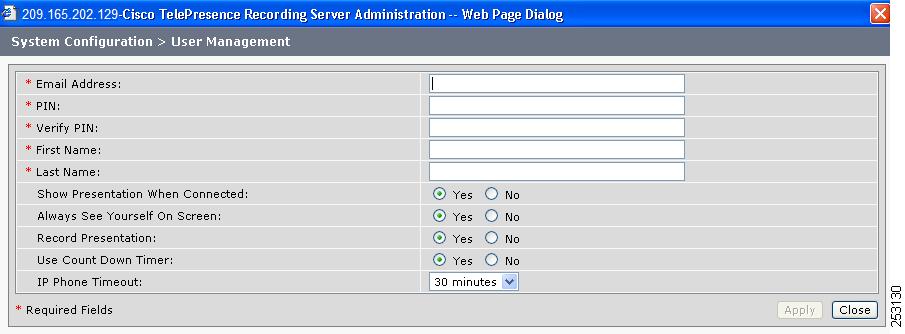
Creating a New User or Modifying Settings for an Existing User
When you click New or Edit, a dialog box appears (see Figure 4-19).
Figure 4-19 System Configuration > User Management—End-user Portal (New or Edit)
Enter settings as described in Table 4-17.
•
•
Note
To learn how to create their own accounts, users should read the "Creating and Viewing Recordings with the Cisco TelePresence Recording Server" chapter in the Cisco TelePresence System User Guide:
http://www.cisco.com/en/US/docs/telepresence/cts_admin/1_6/userguide/cts1_6_ug.html
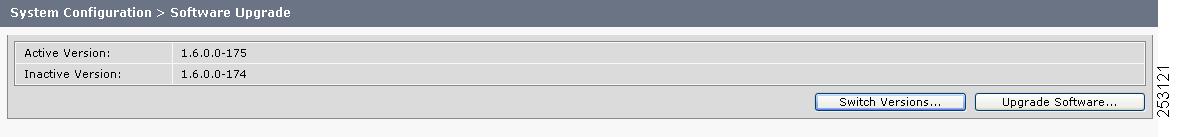
Software Upgrade
Click Software Upgrade in the left menu to display, switch, or upgrade software versions (see Figure 4-20).
Figure 4-20 System Configuration > Software Upgrade
There are two functions to assist you in maintaining the system software, as follows:
•
•
To switch software versions:
•
The system will swap the software versions and reboot. Screens will describe activity.
The active partition in the server hard drive contains the active system image. The software versions that are loaded will be displayed in the Active Version and Inactive Version fields.
To upgrade software:
Step 1
The Source Selection dialog box appears.
If you need to stop the software installation, click the Cancel button when the button is active.
Step 2
If you chose CD-ROM, click Next to go to the File Selection window.
If you chose Network, provide the hostname, login username, password, and the path to the patch file. By default, port 22 is used to access the server; supply the correct port number, if required. Click Next to go to the File Selection window.
Step 3
Step 4
Once the file is loaded, the window displays a Confirmation message.
The software wizard displays the software versions that are installed and provides radio buttons so you can choose to switch the newly loaded software to the active partition.
Step 5
The install wizard displays a dialog window that logs the progress of the update.
Step 6
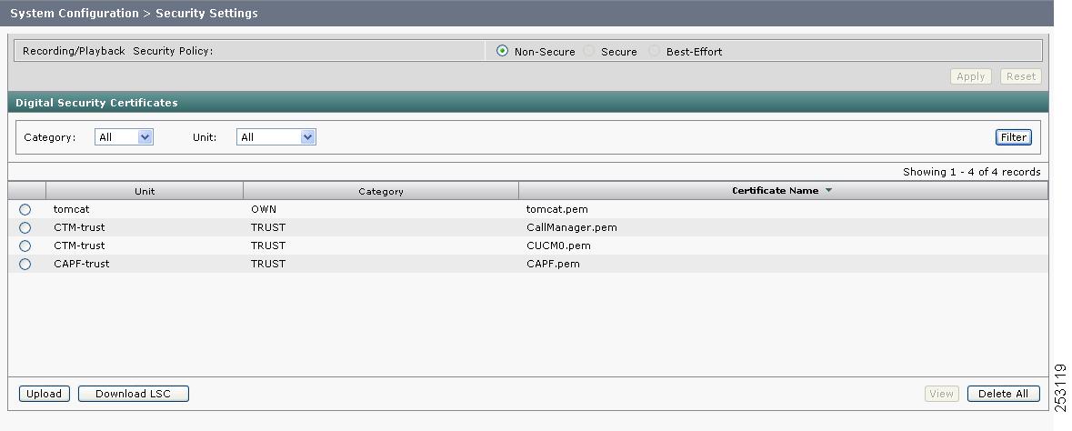
Security Settings
CTRS supports secure communication between Cisco TelePresence devices using Certificate Authority Proxy Function (CAPF). Each Cisco TelePresence product downloads a Locally Significant Certificate (LSC) from a CAPF server; communication between devices is then authenticated using LSCs, Cisco Unified Communications Manager (Unified CM) Root Certificates and a CAPF Root Certificate.
To configure CTRS for security, you need to first complete preliminary steps in Unified CM. You must activate and start CAPF service, create application users, create Unified CM root certificates for every Unified CM server associated with Cisco TelePresence service, and create a CAPF root certificate. Then from the Security Settings window in CTRS, you upload the applicable Unified CM and CAPF root certificates, and download the appropriate LSCs. When all certificates are in place and the LSC is downloaded, the CTRS reboots so that the security settings to take effect.
To configure CAPF Security for CTRS:
Step 1
Step 2
Note
Step 3
•
•
Note
•
•
When finished, click Save.
Note
Step 4
•
•
•
•
•
•
•
Note
Click Save if you are revising an existing profile; Click Add New if you are creating a new profile.
Step 5
Step 6
•
•
•
Click Upload to upload the CAPF Root certificate.
Figure 4-21 System Configuration > Security Settings
Step 7
Note
Step 8
•
•
•
Click Upload to upload the Cisco Unified CM root certificate.
Step 9
•
•
•
•
•
•
Click Download LSC. After the LSC has been successfully downloaded, the CTRS reboots automatically.
Step 10
To choose the default security level:
Step 1
Step 2
•
•
•
Note
Step 3
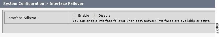
Interface Failover
Click Interface Failover in the left menu to display or modify failover settings for Ethernet adapters (see Figure 4-22).
Figure 4-22 System Configuration > Interface Failover
When enabled, the secondary adapter handles all network traffic if the primary adapter or its connection fails.
To enable interface failover:
Step 1
Step 2
Step 3
Note
To disable interface failover:
Step 1
Step 2
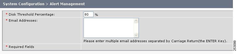
Alert Management
Click Alert Management in the left menu to display or configure alert management settings (see Figure 4-23).
Figure 4-23 System Configuration > Alert Management
Use the Alert Management screen to define the CTRS disk threshold at which export data (either transfer to archive servers or data deletion) will be sent to the users and the email addresses to which these alerts will be sent. Enter settings as described in Table 4-18
Note
•
•
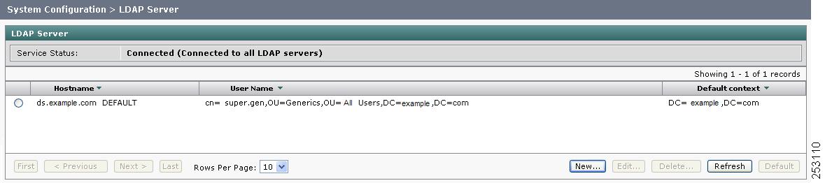
LDAP Configuration
Click LDAD Configuration in the left menu to display or modify the Lightweight Directory Access Protocol (LDAP) configuration (see Figure 4-24).
Figure 4-24 System Configuration > LDAP Configuration
Use the LDAP Configuration screen to assign and make changes to designated LDAP servers to be used with CTRS.
When you first open the LDAP Configuration window, CTRS displays a table listing all of the already-defined LDAP servers. LDAP table fields are described in Table 4-19.
•
•
•
•
•
•
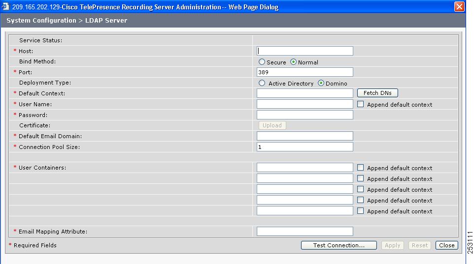
When you click Edit or New, CTRS administration software takes you to the New LDAP Server configuration screen (see Figure 4-25), as described in Table 4-20. Use this screen to edit existing archive server settings or to define new archive servers.
Figure 4-25 System Configuration > LDAP Configuration (New or Edit)
•
•
•
•
Configuring Multiple Domains in an LDAP Forest
To configure multiple domains in an LDAP forest, you must configure all subsequent domains as user containers in the first domain's LDAP configuration page.
For example, you have these two servers:•
Default context: DC=cor1, DC=com
User container: cn=users, DC=cor1, DC=com
•
Default context: DC=cor2, DC=com
User container: cn=users, DC=cor2, DC=com
For CTRS, you must configure LDAP server 1 to include LDAP server 2's user containers. In the configuration page for LDAP server 1, in the User Containers fields, you would enter the following, each in its own field:
•
•
Note
Email Server
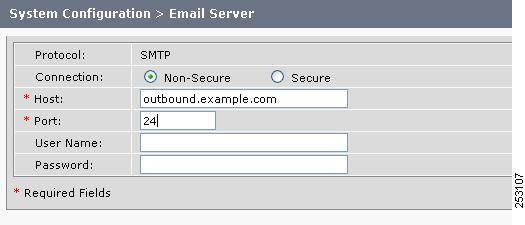
Click Email Server in the left menu to display or modify e-mail server settings (see Figure 4-26).
Figure 4-26 System Configuration > Email Server
Use the Email Server screen to define the e-mail server that CTRS uses to send out alerts and video attachments. Fields in the Email Server screen are described in Table 4-21.
•
•