Feedback
Table Of Contents
Australian Telecommunications Compliance
Warnings for Norway and Sweden
Cisco 575 Ethernet Connection Warning for Norway and Sweden
Cisco 576 LRE 997 Ethernet Connection Warning for Norway and Sweden
Installing the CPE on a Desk (without Mounting Screws)
Installing the CPE on a Desk (with Mounting Screws)
Installing the CPE Under a Desk
Connecting to a Wall-Mounted Telephone Jack
Installation
This chapter describes how to install your customer premises equipment (CPE) device and how to interpret the LEDs to ensure proper operation. Read the topics, and perform these procedures in this order:
•
Connecting to a Wall-Mounted Telephone Jack
Preparing for Installation
Note
Caution
Certain CPE devices are not supported by certain Catalyst 2950 LRE switches. See Table 1-1 to determine which CPEs are supported by which LRE switches.
Warnings
These warnings are translated into several languages in "Translated Safety Warnings."
Warning
Warning
Warning
Warning
Warning
Warning
Warning
Warning
Warning
Warning
Warning
EMC Regulatory Statements
U.S.A.
U.S. regulatory information for this product is in the front matter of this manual.
FCC Requirements
"Modifying the equipment without Cisco's authorization may result in the equipment no longer complying with FCC requirements for Class A or Class B digital devices. In that event, your right to use the equipment may be limited by FCC regulations, and you may be required to correct any interference to radio or television communications at your own expense."
Labeling Requirements
This device complies with Part 15 of the FCC Rules. Operation is subject to the following two conditions: (1) this device may not cause harmful interference, and (2) this device must accept any interference received, including interference that may cause undesired operation.
Canada ICES 003, Issue 3
French
Cet appareil numérique de la classe B est conforme à la norme NMB-003 du Canada.
English
This Class B digital apparatus complies with Canadian ICES-003.
Japan VCCI
This is a Class B product based on the standard of Voluntary Control Council for Interference from Information Technology Equipment (VCCI). If this is used near a radio or television receiver in a domestic environment, it may cause radio interference. Install and use the equipment according to the instruction manual.
Korea
Class B Device. This device is registered for EMC requirements for residential use. This device can be used not only in residential areas but in all other areas.
Australian Telecommunications Compliance
To reduce the risk of electric shock in Australian Long-Reach Ethernet (LRE) installations, use only an Australian Communications Authority (ACA)-approved telephone and handset with a Cisco 575 LRE, 576 LRE 997, or 585 LRE customer premises equipment (CPE) device.
Warnings for Norway and Sweden
Cisco 575 Ethernet Connection Warning for Norway and Sweden
To reduce the risk of electric shock in Norwegian and Swedish LRE installations with a Cisco 575 LRE CPE device, do not connect the Ethernet port of the Cisco 575 LRE CPE to ports of other equipment as described in this warning:
Cisco 576 LRE 997 Ethernet Connection Warning for Norway and Sweden
To reduce the risk of electric shock in Norwegian and Swedish LRE installations with a Cisco 576 LRE 997 CPE device, do not connect the Ethernet port of the Cisco 576 LRE 997 CPE to ports of other equipment as described in this warning:
Germany
Sicherheitshinweise
Lesen Sie diese Sicherheitshinweise sorgfältig durch.
•
•
•
•
•
•
•
•
•
•
•
•
–
–
–
–
–
–
•
•
•
Safety Instructions
Read these safety instructions carefully.
•
•
•
•
•
•
•
•
•
•
•
•
–
–
–
–
–
–
•
•
•
Verifying Package Contents
When you unpack the CPE, be sure that the package contains the items in this list. If any items are missing, notify your authorized Cisco sales representative.
•
•
•
–
–
–
–
•
•
Note
Installing the CPE
You can install the CPE on or under a desk or on a wall. Before you begin the installation, decide where to mount the CPE by reviewing the illustrations in these sections:
•
•
•
Installing the CPE on a Desk (without Mounting Screws)
The CPE can be installed on top of a desk with mounting screws or just placed on the desk. If you do not wish to install the CPE with mounting screws, follow these steps:
Step 1
Step 2
Step 3
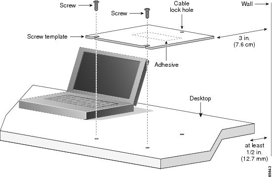
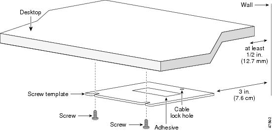
Installing the CPE on a Desk (with Mounting Screws)
If you wish to secure the CPE on a desktop, you can use mounting screws. Follow these steps:
Step 1
Step 2
Step 3
Note
Note
Figure 2-1 Installing the Mounting Screws on Top of a Desk
Note
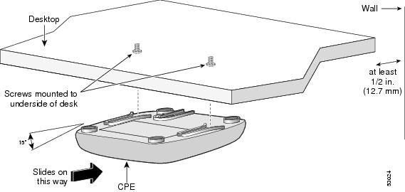
Step 4
Step 5
Step 6
Step 7
Step 8
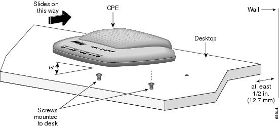
Step 9
Figure 2-2 Mounting the CPE On Top of a Desk
Note
Note
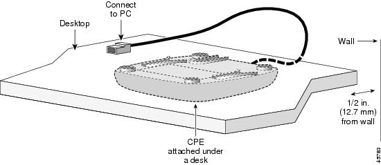
Installing the CPE Under a Desk
Tip
Follow these steps to install the CPE under a desk:
Step 1
Step 2
Step 3
Note
Note
Figure 2-3 Installing the Mounting Screws Under a Desk
Note
Step 4
Step 5
Step 6
Step 7
Step 8
Step 9
Figure 2-4 Mounting the CPE Under a Desk
Note
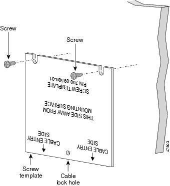
Installing the CPE on a Wall
Tip
Step 1
Note
Step 2
Note
Figure 2-5 Installing the Mounting Screws on a Wall
Step 3
Note
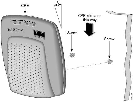
Step 4
Step 5
Step 6
Step 7
Step 8
Step 9
Figure 2-6 Installing the CPE On a Wall
Note
Connecting to a 10/100 Port
The LRE CPE 10/100 ports configure themselves to operate at the speed of the attached devices. Connecting devices that do not autonegotiate or that have had speed and duplex parameters manually set can reduce performance or result in no linkage.
If the attached ports do not support autonegotiation, you can explicitly set the speed and duplex parameters.
Note
Note
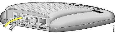
Follow these steps to connect to 10BASE-T and 100BASE-T devices:
Step 1
Note
Figure 2-7 Connecting to a 10/100 LRE Port
Step 2
If you are installing a Cisco 585 LRE CPE and are connecting several devices to it, repeat Steps 1 and 2 until all devices are connected.
Note
Figure 2-8 Ethernet Cable Lying on a Desktop
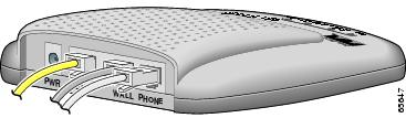
Connecting to a Wall-Mounted Telephone Jack
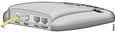
The CPE connects to a Catalyst LRE switch through the telephone wiring of a building. Follow these steps to connect the CPE to an LRE switch:
Step 1
Caution
Caution
Figure 2-9 Connecting to a WALL port
Note
Step 2
Connecting to a Telephone
These limitations and restrictions apply when you use a plain old telephone service (POTS) splitter with the Catalyst 2950 LRE switches and Cisco LRE CPE devices:
•
Digital telephones connected to digital PBX switches that use frequencies above 700 kHz do not work when sharing a line with LRE signals. Due to the proprietary nature of digital PBX switches, some digital PBX switch services use frequencies above 700 kHz.
•
•
to 120 kHz frequency range.•
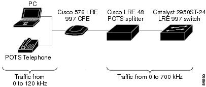
In Figure 2-10, only traffic from 0 to 120 kHz can pass from a device attached to the CPE, such as a computer or telephone, to the CPE, a splitter, and a switch. In the reverse direction, traffic from 0 to 700 kHz can pass through the switch and splitter to the CPE, but only traffic from 0 to 120 kHz can pass through the CPE to a computer or a telephone.
For more information, refer to the Installation and Warranty Notes for the Cisco LRE 48 POTS Splitter.
Figure 2-10 Limitations Using a Cisco LRE 48 POTS Splitter with a Catalyst 2950ST-24 LRE 997 Switch and Cisco 576 LRE CPE
Follow these steps to connect the CPE to a telephone:
Step 1
Caution
Caution
Note
Step 2
Figure 2-11 Wall Jack to Telephone Connection through an LRE CPE
Note
Note
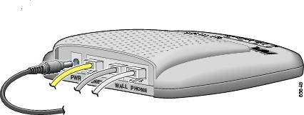
Connecting the Power Cord
Follow these steps to connect the power cord to the CPE:
Step 1
Figure 2-12 Connecting the Power Cord
Caution
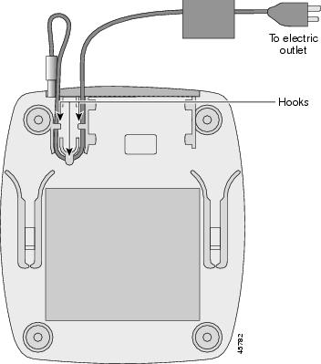
Step 2
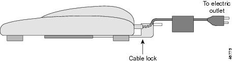
Figure 2-13 Securing a Power Cord to the Bottom of the CPE
Caution
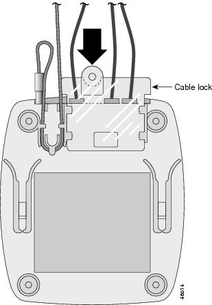
Attaching the Cable Lock
The optional cable lock provides extra security to prevent someone from easily removing the CPE from a desk or wall.
To install the cable lock, follow these steps:
Step 1
Step 2
Figure 2-14 Attaching the Cable Lock
Note
Figure 2-15 Cable Lock Installed on CPE (Side View)
Step 3
Note
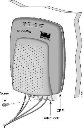
Figure 2-16 Securing the Cable Lock to a Desk- or Wall-Mounted CPE with Mounting Screw
Powering On the CPE
Follow these steps to connect the CPE to AC power:
Step 1
Step 2
The ETH link LED (on the Cisco 575 LRE CPE or Cisco 576 LRE 997 CPE), the ETH1 through ETH4 LEDs (on the Cisco 585 LRE CPE), and the READY LED turn on when the appropriate equipment is connected.
Where to Go Next
CPE configuration, data speed settings, and monitoring are controlled from a Catalyst LRE switch. For more information, refer to the switch hardware installation guide and the switch software configuration guide for your switch model.