Feedback
Table Of Contents
Overview
This chapter describes the Cisco LRE CPE, a Long-Reach Ethernet (LRE) customer premises equipment (CPE) device and has these topics:
•
Features
•
•
Features
A Cisco LRE CPE device, hereafter referred to as the CPE, is based on very-high-data-rate digital subscriber line (VDSL) technology. The CPE connects a computer or laptop to a Catalyst LRE switch at distances of up to 4921 feet (1500 meters) by using LRE technology over ordinary telephone lines.
Note
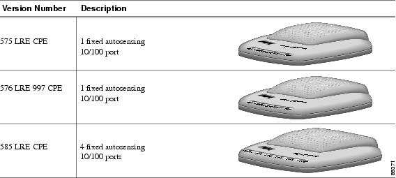
The Cisco 575 LRE CPE, Cisco 576 LRE 997 CPE, and the Cisco 585 LRE CPE have these features:
•
•
•
•
•
Note
•
Certain Cisco LRE CPE devices are not supported by certain Catalyst 2950 LRE switches. In Table 1-1, Yes means that the CPE is supported by the switch; No means that the CPE is not supported by the switch.
Figure 1-1 shows the Cisco LRE CPE models.
Figure 1-1 Cisco LRE CPE models
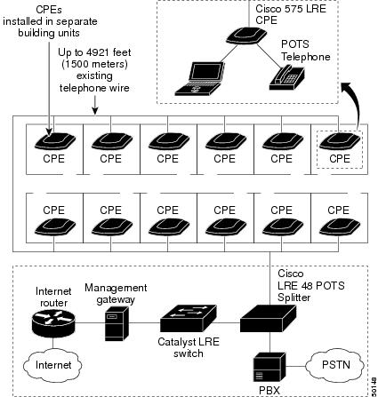
If additional telephone services such as voice or ISDN traffic will be carried on the same telephone lines, a plain old telephone service (POTS) splitter can be installed to separate LRE traffic from other telephone services. The splitter routes the high-frequency LRE data to the switch and the low-frequency telephone services to the private branch exchange (PBX) switch or public switched telephone network (PSTN).
For limitations and restrictions on when you use a POTS splitter with the Catalyst 2950 LRE switches and Cisco LRE CPE devices, see the "Connecting to a Telephone" section.
In a typical installation, a CPE is installed in each room of a multidwelling tenant building. The CPE data rates and profile settings are controlled by a Catalyst 2950 LRE switch. Figure 1-2 shows a typical LRE installation.
Figure 1-2 Typical LRE Installation
For installations where telephone services will be routed to a PBX switch, you can install a Cisco LRE POTS Splitter (PS-1M-LRE-48). For more information about this POTS splitter, refer to the Installation and Warranty Notes for the Cisco LRE 48 POTS Splitter.
If the building does not use a PBX and telephone services are sent directly to an outside PSTN, you must provide a homologated POTS splitter. For more information about homologated POTS splitters, contact your Cisco sales representative.
For more information about installing a Catalyst LRE switch, refer to the switch hardware installation guide.
Front-Panel Description
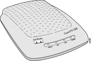
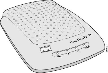
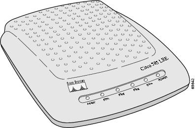
Each Cisco LRE CPE has a READY LED and a POWER LED. The Cisco 575 LRE CPE and Cisco 576 LRE 997 CPE also have an ACT LED and an ETH LED. The Cisco 585 LRE CPE also has four LEDs, labeled ETH1 through ETH4.
Figure 1-3 to Figure 1-5 show the front panels of the CPEs. Table 1-2 and Table 1-3 list the front-panel LEDs and their meanings.
Figure 1-3 Front Panel of the Cisco 575 LRE CPE
Figure 1-4 Front Panel of the Cisco 576 LRE 997 CPE
Figure 1-5 Front Panel of the Cisco 585 LRE CPE
Rear-Panel Description
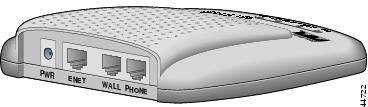
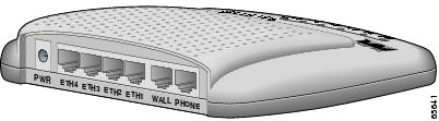
The LRE CPE rear panels have a power connector, two RJ-11 connectors, and, depending on the model, either one or four RJ-45 Ethernet connectors.
Figure 1-6 and Figure 1-7 show the rear panels of the CPEs. Table 1-4 and Table 1-5 list the rear-panel connectors and their descriptions.
Figure 1-6 Rear Panel of the Cisco 575 LRE CPE and Cisco 576 LRE 997 CPE
Figure 1-7 Rear Panel of the Cisco 585 LRE CPE