Feedback
Table Of Contents
Connector and Cable Specifications
Ethernet Straight-Through Cable Pinouts
Telephone Straight-Through and Rollover Cable Pinouts
Identifying a Telephone Rollover Cable
Connector and Cable Specifications
This appendix describes the and customer premises equipment (CPE) connectors and the cables that you use to connect the CPE to other devices.
Connector Specifications
10/100 Ports
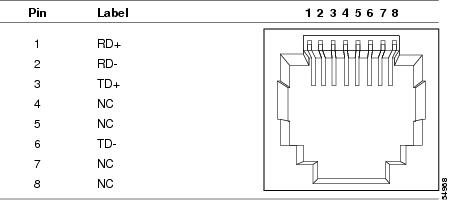
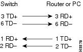
The CPE 10/100 ports (the ENET port on the Cisco 575 LRE CPE and the Cisco 576 LRE 997 CPE and on the ENET1 through ENET4 ports on the Cisco 585 LRE CPE) use RJ-45 connectors with Ethernet pinouts. The ports have the transmit (TD) and receive (RD) signals internally crossed so that a straight-through Ethernet cable (included only with the Cisco 575 LRE CPE and Cisco 576 LRE 997 CPE) can be attached to the port. Figure B-1 shows the pinouts.
Figure B-1 RJ-45 Connector Pinouts
When connecting a CPE 10/100 port to a PC or laptop, you must use a straight-through Ethernet cable wired for 10BASE-T or 100BASE-T. Figure B-5 shows the straight-through cable schematics.
WALL Port
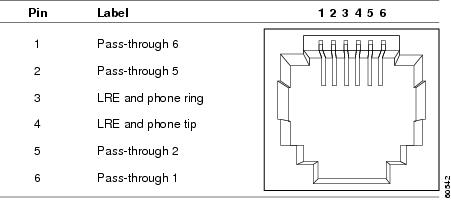
The WALL port uses an RJ-11 telephone connector to connect to the Long-Reach Ethernet (LRE) switch. See Figure B-2 for the connector pinouts.
Figure B-2 WALL Port Connector Pinouts
PHONE Port
The PHONE port uses an RJ-11 connector. LRE operation only requires one wire pair (pins 3 and 4) to carry LRE traffic. Therefore, you can use one-, two-, or three-pair telephone cable. However, you must use a two- or three-pair cable for telephones that carry power or other services. We recommend using a three-pair telephone cable to connect a telephone to the CPE. (See Figure B-6 and Figure B-7.)
Note
Pins 3 and 4 are internally crossed between the CPE WALL port and the CPE PHONE port on the Cisco 575 LRE CPE, the Cisco 576 LRE 997 CPE, and the Cisco 585 LRE CPE devices.
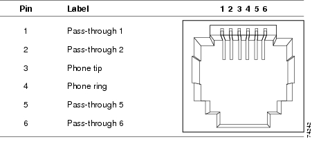
Pins 1, 2, 5, and 6 on the WALL port of the Cisco 575 LRE CPE and the Cisco 576 LRE 997 CPE are internally connected to the corresponding pins of the PHONE port. (See Figure B-3.)
Figure B-3 Cisco 575 LRE CPE and Cisco 576 LRE 997 CPE PHONE Port Connector Pinouts
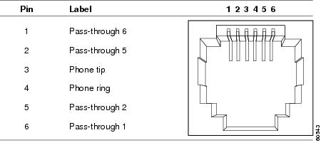
Pins 1, 2, 5, and 6 on the WALL port of the Cisco 585 LRE CPE are internally crossed. (See Figure B-4.)
Figure B-4 Cisco 585 LRE CPE PHONE Port Connector Pinouts
Note
Cable Specifications
This section describes the cables that you use to connect the CPE to other devices.
Ethernet Straight-Through Cable Pinouts
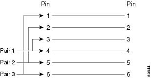
The schematics of a straight-through Ethernet cable (included with the Cisco 575 LRE CPE and the Cisco 576 LRE 997 CPE) are shown in Figure B-5.
Figure B-5 Ethernet Straight-Through Cable Pinouts
Telephone Straight-Through and Rollover Cable Pinouts
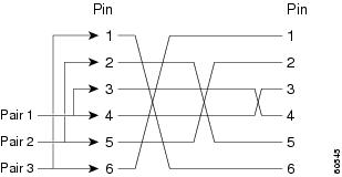
The schematics of straight-through and rollover telephone cables are shown in Figure B-6 and Figure B-7.
Figure B-6 Telephone Straight-Through Cable Schematic
Figure B-7 Telephone Rollover Cable Schematic
Identifying a Telephone Rollover Cable
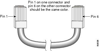
You can identify a telephone rollover cable by comparing the two RJ-21 connectors at each end of the cable. Hold the cable ends side-by-side, with the tab facing away from you. The wire connected to the pin on the outside of the left RJ-21 connector should be the same color as the wire connected to the pin on the outside of the right RJ-21 connector. (See Figure B-8.)
Figure B-8 Identifying a Telephone Rollover Cable