-
Catalyst 3550 Multilayer Switch Software Configuration Guide, 12.1(9)EA1
-
Index
-
Preface
-
Overview
-
Using the Command-Line Interface
-
Getting Started with CMS
-
Configuring the Switch IP Address and Default Gateway
-
Configuring IE2100 CNS Agents
-
Clustering Switches
-
Administering the Switch
-
Configuring 802.1X Port-Based Authentication
-
Configuring Interface Characteristics
-
Creating and Maintaining VLANs
-
Configuring VTP
-
Configuring Voice VLAN
-
Configuring 802.1Q and Layer 2 Protocol Tunneling
-
Configuring STP
-
Configuring RSTP and MSTP
-
Configuring Optional Spanning-Tree Features
-
Configuring the DHCP Option 82 for Subscriber Identification
-
Configuring IGMP Snooping and MVR
-
Configuring Port-Based Traffic Control
-
Configuring CDP
-
Configuring UDLD
-
Configuring SPAN
-
Configuring RMON
-
Configuring System Message Logging
-
Configuring SNMP
-
Configuring Network Security with ACLs
-
Configuring QoS
-
Configuring EtherChannels
-
Configuring IP Unicast Routing
-
Configuring HSRP
-
Configuring IP Multicast Routing
-
Configuring MSDP
-
Configuring Fallback Bridging
-
Troubleshooting
-
Supported MIBs
-
Working with the IOS File System, Configuration Files, and Software Images
-
Unsupported CLI Commands for Release 12.1(9)EA1
-
 Feedback
Table Of Contents
Understanding Spanning-Tree Features
Supported Spanning-Tree Instances
Bridge ID, Switch Priority, and Extended System ID
Creating the Spanning-Tree Topology
Spanning-Tree Interface States
Spanning-Tree Address Management
Spanning Tree and Redundant Connectivity
Accelerated Aging to Retain Connectivity
Configuring Spanning-Tree Features
Configuring a Secondary Root Switch
Configuring the Switch Priority of a VLAN
Configuring the Forwarding-Delay Time for a VLAN
Configuring the Maximum-Aging Time for a VLAN
Configuring STP for Use in a Cascaded Stack
Displaying Spanning-Tree Status
Configuring STP
This chapter describes how to configure the Spanning Tree Protocol (STP) on your switch.
For information about the Rapid Spanning Tree Protocol (RSTP) and the Multiple Spanning Tree Protocol (MSTP), see "Configuring RSTP and MSTP." For information about optional spanning-tree features, see "Configuring Optional Spanning-Tree Features."
Note
For complete syntax and usage information for the commands used in this chapter, refer to the Catalyst 3550 Multilayer Switch Command Reference for this release.
This chapter consists of these sections:
•
•
•
Understanding Spanning-Tree Features
This section describes how spanning-tree features work. It includes this information:
•
•
•
•
•
•
•
STP Overview
STP is a Layer 2 link management protocol that provides path redundancy while preventing loops in the network. For a Layer 2 Ethernet network to function properly, only one active path can exist between any two stations. Spanning-tree operation is transparent to end stations, which cannot detect whether they are connected to a single LAN segment or a switched LAN of multiple segments.
When you create fault-tolerant internetworks, you must have a loop-free path between all nodes in a network. The spanning-tree algorithm calculates the best loop-free path throughout a switched Layer 2 network. Switches send and receive spanning-tree frames, called bridge protocol data units (BPDUs), at regular intervals. The switches do not forward these frames, but use the frames to construct a loop-free path.
Multiple active paths among end stations cause loops in the network. If a loop exists in the network, end stations might receive duplicate messages. Switches might also learn end-station MAC addresses on multiple Layer 2 interfaces. These conditions result in an unstable network.
Spanning tree defines a tree with a root switch and a loop-free path from the root to all switches in the Layer 2 network. Spanning tree forces redundant data paths into a standby (blocked) state. If a network segment in the spanning tree fails and a redundant path exists, the spanning-tree algorithm recalculates the spanning-tree topology and activates the standby path.
When two interfaces on a switch are part of a loop, the spanning-tree port priority and path cost settings determine which interface is put in the forwarding state and which is put in the blocking state. The port priority value represents the location of an interface in the network topology and how well it is located to pass traffic. The path cost value represents media speed.
Supported Spanning-Tree Instances
The switch supports the per-VLAN spanning tree (PVST) and a maximum of 128 spanning-tree instances. For information about how spanning tree interoperates with the VLAN Trunking Protocol (VTP), see the "STP Configuration Guidelines" section.
Bridge Protocol Data Units
The stable, active spanning-tree topology of a switched network is determined by these elements:
•
•
•
When the switches in a network are powered up, each functions as the root switch. Each switch sends a configuration BPDU through all of its ports. The BPDUs communicate and compute the spanning-tree topology. Each configuration BPDU contains this information:
•
•
•
•
•
•
When a switch receives a configuration BPDU that contains superior information (lower bridge ID, lower path cost, and so forth), it stores the information for that port. If this BPDU is received on the root port of the switch, the switch also forwards it with an updated message to all attached LANs for which it is the designated switch.
If a switch receives a configuration BPDU that contains inferior information to that currently stored for that port, it discards the BPDU. If the switch is a designated switch for the LAN from which the inferior BPDU was received, it sends that LAN a BPDU containing the up-to-date information stored for that port. In this way, inferior information is discarded, and superior information is propagated on the network.
A BPDU exchange results in these actions:
•
•
•
•
•
•
Election of the Root Switch
All switches in the Layer 2 network participating in spanning tree gather information about other switches in the network through an exchange of BPDU data messages. This exchange of messages results in these actions:
•
•
•
For each VLAN, the switch with the highest switch priority (the lowest numerical priority value) is elected as the root switch. If all switches are configured with the default priority (32768), the switch with the lowest MAC address in the VLAN becomes the root switch. The switch priority value occupies the most significant bits of the bridge ID.
When you change the switch priority value, you change the probability that the switch will be elected as the root switch. Configuring a higher value decreases the probability; a lower value increases the probability.
The root switch is the logical center of the spanning-tree topology in a switched network. All paths that are not needed to reach the root switch from anywhere in the switched network are placed in the spanning-tree blocking mode.
BPDUs contain information about the sending switch and its ports, including switch and MAC addresses, switch priority, port priority, and path cost. Spanning tree uses this information to elect the root switch and root port for the switched network and the root port and designated port for each switched segment.
Bridge ID, Switch Priority, and Extended System ID
The IEEE 802.1D standard requires that each switch has an unique bridge identifier (bridge ID), which determines the selection of the root switch. Because each VLAN is considered as a different logical bridge with PVST+, the same switch must have as many different bridge IDs as VLANs configured on it. Each VLAN on the switch has a unique 8-byte bridge ID; the two most-significant bytes are used for the switch priority, and the remaining six bytes are derived from the switch MAC address.
In Release 12.1(8)EA1 and later, Catalyst 3550 switches support the 802.1T spanning-tree extensions, and some of the bits previously used for the switch priority are now used as the VLAN identifier. The result is that fewer MAC addresses are reserved for the switch, and a larger range of VLAN IDs can be supported, all while maintaining the uniqueness of the bridge ID. As shown in Table 14-1, the two bytes previously used for the switch priority are reallocated into a 4-bit priority value and a 12-bit extended system ID value equal to the VLAN ID. In earlier releases, the switch priority is a 16-bit value.
Spanning tree uses the extended system ID, the switch priority, and the allocated spanning-tree MAC address to make the bridge ID unique for each VLAN. With earlier releases, spanning tree used one MAC address per VLAN to make the bridge ID unique for each VLAN.
Support for the extended system ID affects how you manually configure the root switch, the secondary root switch, and the switch priority of a VLAN. For more information, see the "Configuring the Root Switch" section, "Configuring a Secondary Root Switch" section, and "Configuring the Switch Priority of a VLAN" section.
Spanning-Tree Timers
Table 14-2 describes the timers that affect the entire spanning-tree performance.
Creating the Spanning-Tree Topology
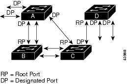
In Figure 14-1, Switch A is elected as the root switch because the switch priority of all the switches is set to the default (32768) and Switch A has the lowest MAC address. However, because of traffic patterns, number of forwarding interfaces, or link types, Switch A might not be the ideal root switch. By increasing the priority (lowering the numerical value) of the ideal switch so that it becomes the root switch, you force a spanning-tree recalculation to form a new topology with the ideal switch as the root.
Figure 14-1 Spanning-Tree Topology
When the spanning-tree topology is calculated based on default parameters, the path between source and destination end stations in a switched network might not be ideal. For instance, connecting higher-speed links to an interface that has a higher number than the root port can cause a root-port change. The goal is to make the fastest link the root port.
For example, assume that one port on Switch B is a Gigabit Ethernet link and that another port on Switch B (a 10/100 link) is the root port. Network traffic might be more efficient over the Gigabit Ethernet link. By changing the spanning-tree port priority on the Gigabit Ethernet interface to a higher priority (lower numerical value) than the root port, the Gigabit Ethernet interface becomes the new root port.
Spanning-Tree Interface States
Propagation delays can occur when protocol information passes through a switched LAN. As a result, topology changes can take place at different times and at different places in a switched network. When an interface transitions directly from nonparticipation in the spanning-tree topology to the forwarding state, it can create temporary data loops. Interfaces must wait for new topology information to propagate through the switched LAN before starting to forward frames. They must allow the frame lifetime to expire for forwarded frames that have used the old topology.
Each Layer 2 interface on a switch using spanning tree exists in one of these states:
•
•
•
•
•
An interface moves through these states:
•
•
•
•
•
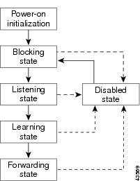
Figure 14-2 illustrates how an interface moves through the states.
Figure 14-2 Spanning-Tree Interface States
When you power up the switch, STP is enabled by default, and every interface in the switch, VLAN, or network goes through the blocking state and the transitory states of listening and learning. Spanning tree stabilizes each interface at the forwarding or blocking state.
When the spanning-tree algorithm places a Layer 2 interface in the forwarding state, this process occurs:
1.
2.
3.
4.
Blocking State
A Layer 2 interface in the blocking state does not participate in frame forwarding. After initialization, a BPDU is sent to each interface in the switch. A switch initially functions as the root until it exchanges BPDUs with other switches. This exchange establishes which switch in the network is the root or root switch. If there is only one switch in the network, no exchange occurs, the forward-delay timer expires, and the interfaces move to the listening state. An interface always enters the blocking state after switch initialization.
An interface in the blocking state performs as follows:
•
•
•
•
Listening State
The listening state is the first state a Layer 2 interface enters after the blocking state. The interface enters this state when the spanning tree determines that the interface should participate in frame forwarding.
An interface in the listening state performs as follows:
•
•
•
•
Learning State
A Layer 2 interface in the learning state prepares to participate in frame forwarding. The interface enters the learning state from the listening state.
An interface in the learning state performs as follows:
•
•
•
•
Forwarding State
A Layer 2 interface in the forwarding state forwards frames. The interface enters the forwarding state from the learning state.
An interface in the forwarding state performs as follows:
•
•
•
•
Disabled State
A Layer 2 interface in the disabled state does not participate in frame forwarding or in the spanning tree. An interface in the disabled state is nonoperational.
A disabled interface performs as follows:
•
•
•
•
Spanning-Tree Address Management
IEEE 802.1D specifies 17 multicast addresses, ranging from 0x00180C2000000 to 0x0180C2000010, to be used by different bridge protocols. These addresses are static addresses that cannot be removed.
Regardless of the spanning-tree state, the switch receives but does not forward packets destined for addresses between 0x0180c2000000 and 0x1080C200000F.
If STP is enabled, the switch CPU receives packets destined for 0x0180C2000000 and 0x0180C2000010. If STP is disabled, the switch forwards those packets as unknown multicast addresses.
STP and IEEE 802.1Q Trunks
The IEEE 802.1Q standard for VLAN trunks imposes some limitations on the spanning-tree strategy for a network. The standard requires only one spanning-tree instance for all VLANs allowed on the trunks. However, in a network of Cisco switches connected through 802.1Q trunks, the switches maintain one spanning-tree instance for each VLAN allowed on the trunks.
When you connect a Cisco switch to a non-Cisco device through an 802.1Q trunk, the Cisco switch uses per-VLAN spanning tree+ (PVST+) to provide spanning-tree interoperability. It combines the spanning-tree instance of the 802.1Q VLAN of the trunk with the spanning-tree instance of the non-Cisco 802.1Q switch.
However, all PVST+ information is maintained by Cisco switches separated by a cloud of non-Cisco 802.1Q switches. The non-Cisco 802.1Q cloud separating the Cisco switches is treated as a single trunk link between the switches.
PVST+ is automatically enabled on 802.1Q trunks, and no user configuration is required. The external spanning-tree behavior on access ports and Inter-Switch Link (ISL) trunk ports is not affected by PVST+.
For more information on 802.1Q trunks, see "Configuring VLANs."
VLAN-Bridge STP
Cisco VLAN-bridge STP is used with the fallback bridging feature (bridge groups), which forwards non-IP protocols such as DECnet or IPX between two or more VLAN bridge domains or routed ports. The VLAN-bridge STP allows the bridge groups to form a spanning tree on top of the individual VLAN spanning trees to prevent loops from forming if there are multiple connections among VLANs. It also prevents the individual spanning trees from the VLANs being bridged from collapsing into a single spanning tree.
To support VLAN-bridge STP, some of the spanning-tree timers are increased. To use the fallback bridging feature, you must have the enhanced multilayer switch image installed on your switch. For more information, see "Configuring Fallback Bridging."
Spanning Tree and Redundant Connectivity
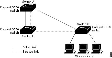
You can create a redundant backbone with spanning tree by connecting two switch interfaces to another device or to two different devices. Spanning tree automatically disables one interface but enables it if the other one fails, as shown in Figure 14-3. If one link is high-speed and the other is low-speed, the low-speed link is always disabled. If the speeds are the same, the port priority and port ID are added together, and spanning tree disables the link with the lowest value.
Figure 14-3 Spanning Tree and Redundant Connectivity
You can also create redundant links between switches by using EtherChannel groups. For more information, see "Configuring EtherChannels."
Accelerated Aging to Retain Connectivity
The default for aging dynamic addresses is 5 minutes, the default setting of the mac-address-table aging-time global configuration command. However, a spanning-tree reconfiguration can cause many station locations to change. Because these stations could be unreachable for 5 minutes or more during a reconfiguration, the address-aging time is accelerated so that station addresses can be dropped from the address table and then relearned. The accelerated aging is the same as the forward-delay parameter value (spanning-tree vlan vlan-id forward-time seconds global configuration command) when the spanning tree reconfigures.
Because each VLAN is a separate spanning-tree instance, the switch accelerates aging on a per-VLAN basis. A spanning-tree reconfiguration on one VLAN can cause the dynamic addresses learned on that VLAN to be subject to accelerated aging. Dynamic addresses on other VLANs can be unaffected and remain subject to the aging interval entered for the switch.
Configuring Spanning-Tree Features
These sections include spanning-tree configuration information:
•
•
•
•
•
•
Default STP Configuration
Table 14-3 shows the default STP configuration.
STP Configuration Guidelines
If more VLANs are defined in the VTP than there are spanning-tree instances, you can enable STP on only 128 VLANs. The remaining VLANs operate with spanning tree disabled. If the number of VLANs exceeds 128, we recommend that you enable the MSTP to map multiple VLANs to a single spanning-tree instance. For more information, see the "Configuring RSTP and MSTP."
If 128 instances of spanning tree are already in use, you can disable STP on one of the VLANs and then enable it on the VLAN where you want it to run. Use the no spanning-tree vlan vlan-id global configuration command to disable STP on a specific VLAN, and use the spanning-tree vlan vlan-id global configuration command to enable STP on the desired VLAN.
Caution
Note
Spanning-tree commands determine the configuration of VLAN spanning-tree instances. You create a spanning-tree instance when you assign an interface to a VLAN. The spanning-tree instance is removed when the last interface is moved to another VLAN. You can configure switch and port parameters before a spanning-tree instance is created; these parameters are applied when the spanning-tree instance is created.
Disabling STP
STP is enabled by default on VLAN 1 and on all newly created VLANs up to the spanning-tree limit specified in Table 14-3. Disable STP only if you are sure there are no loops in the network topology.
Caution
Beginning in privileged EXEC mode, follow these steps to disable STP on a per-VLAN basis:
To re-enable STP, use the spanning-tree vlan vlan-id global configuration command.
Configuring the Root Switch
The switch maintains a separate spanning-tree instance for each active VLAN configured on it. A bridge ID, consisting of the switch priority and the switch MAC address, is associated with each instance. For each VLAN, the switch with the lowest bridge ID becomes the root switch for that VLAN.
To configure a switch to become the root, use the spanning-tree vlan vlan-id root global configuration command to modify the switch priority from the default value (32768) to a significantly lower value so that the switch becomes the root switch for the specified VLAN. When you enter this command, the switch checks the switch priority of the root switches for each VLAN. Because of the extended system ID support, the switch sets its own priority for the specified VLAN to 24576 if this value will cause this switch to become the root for the specified VLAN.
If any root switch for the specified VLAN has a switch priority lower than 24576, the switch sets its own priority for the specified VLAN to 4096 less than the lowest switch priority. (4096 is the value of the least-significant bit of a 4-bit switch priority value as shown in Table 14-1.)
Note
Before Release 12.1(8)EA1, entering the spanning-tree vlan vlan-id root global configuration command on a Catalyst 3550 switch (no extended system ID) caused it to set its own switch priority for the specified VLAN to 8192 if this value caused this switch to become the root for the specified VLAN. If any root switch for the specified VLAN has a switch priority lower than 8192, the switch sets its own priority for the specified VLAN to 1 less than the lowest switch priority.
These examples show the effect of the spanning-tree vlan vlan-id root command with and without the extended system ID support:
•
•
Note
Note
Use the diameter keyword to specify the Layer 2 network diameter (that is, the maximum number of switch hops between any two end stations in the Layer 2 network). When you specify the network diameter, the switch automatically sets an optimal hello time, forward-delay time, and maximum-age time for a network of that diameter, which can significantly reduce the convergence time. You can use the hello keyword to override the automatically calculated hello time.
Note
Beginning in privileged EXEC mode, follow these steps to configure a switch as the root switch:
To return the switch to its default setting, use the no spanning-tree vlan vlan-id root global configuration command.
Configuring a Secondary Root Switch
When you configure a Catalyst 3550 switch that supports the extended system ID as the secondary root, the switch priority is modified from the default value (32768) to 28672. The switch is then likely to become the root switch for the specified VLAN if the primary root switch fails. This is assuming that the other network switches use the default switch priority of 32768 and therefore are unlikely to become the root switch. For Catalyst 3550 switches without the extended system ID support (software earlier than Release 12.1(8)EA1), the switch priority is changed to 16384.
You can execute this command on more than one switch to configure multiple backup root switches. Use the same network diameter and hello-time values as you used when you configured the primary root switch with the spanning-tree vlan vlan-id root primary global configuration command.
Beginning in privileged EXEC mode, follow these steps to configure a switch as the secondary root switch:
Step 1
configure terminal
Enter global configuration mode.
Step 2
spanning-tree vlan vlan-id root secondary [diameter net-diameter [hello-time seconds]]
Configure a switch as the secondary root switch.
•
•
•
Use the same network diameter and hello-time values that you used when configuring the primary root switch. See the "Configuring the Root Switch" section.
Step 3
end
Return to privileged EXEC mode.
Step 4
show spanning-tree detail
Verify your entries.
Step 5
copy running-config startup-config
(Optional) Save your entries in the configuration file.
To return the switch to its default setting, use the no spanning-tree vlan vlan-id root global configuration command.
Configuring the Port Priority
If a loop occurs, spanning tree uses the port priority when selecting an interface to put into the forwarding state. You can assign higher priority values (lower numerical values) to interfaces that you want selected first and lower priority values (higher numerical values) that you want selected last. If all interfaces have the same priority value, spanning tree puts the interface with the lowest interface number in the forwarding state and blocks the other interfaces.
Cisco IOS uses the port priority value when the interface is configured as an access port and uses VLAN port priority values when the interface is configured as a trunk port.
Beginning in privileged EXEC mode, follow these steps to configure the port priority of an interface:
Note
To return the interface to its default setting, use the no spanning-tree [vlan vlan-id] port-priority interface configuration command. For information on how to configure load sharing on trunk ports by using spanning-tree port priorities, see the "Load Sharing Using STP" section.
Configuring the Path Cost
The spanning-tree path cost default value is derived from the media speed of an interface. If a loop occurs, spanning tree uses cost when selecting an interface to put in the forwarding state. You can assign lower cost values to interfaces that you want selected first and higher cost values that you want selected last. If all interfaces have the same cost value, spanning tree puts the interface with the lowest interface number in the forwarding state and blocks the other interfaces.
Spanning tree uses the cost value when the interface is configured as an access port and uses VLAN port cost values when the interface is configured as a trunk port.
Beginning in privileged EXEC mode, follow these steps to configure the cost of an interface:
Note
To return the interface to its default setting, use the no spanning-tree [vlan vlan-id] cost interface configuration command. For information on how to configure load sharing on trunk ports using spanning-tree path costs, see the "Load Sharing Using STP" section.
Configuring the Switch Priority of a VLAN
You can configure the switch priority and make it more likely that the switch will be chosen as the root switch.
Note
Beginning in privileged EXEC mode, follow these steps to configure the switch priority of a VLAN:
To return the switch to its default setting, use the no spanning-tree vlan vlan-id priority global configuration command.
Configuring the Hello Time
You can configure the interval between the generation of configuration messages by the root switch by changing the hello time.
Note
Beginning in privileged EXEC mode, follow these steps to configure the hello time of a VLAN:
To return the switch to its default setting, use the no spanning-tree vlan vlan-id hello-time global configuration command.
Configuring the Forwarding-Delay Time for a VLAN
Beginning in privileged EXEC mode, follow these steps to configure the forwarding-delay time for a VLAN:
To return the switch to its default setting, use the no spanning-tree vlan vlan-id forward-time global configuration command.
Configuring the Maximum-Aging Time for a VLAN
Beginning in privileged EXEC mode, follow these steps to configure the maximum-aging time for a VLAN:
To return the switch to its default setting, use the no spanning-tree vlan vlan-id max-age global configuration command.
Configuring STP for Use in a Cascaded Stack
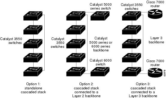
STP uses default values that can be reduced when configuring your switch in cascaded configurations. If a root switch is part of a cluster that is one switch from a cascaded stack, you can customize spanning tree to reconverge more quickly after a switch failure. Figure 14-4 shows switches in three cascaded stacks that use the GigaStack GBIC. Table 14-4 shows the default STP settings and those that are acceptable for these configurations.
Figure 14-4 Gigabit Ethernet Stack
Displaying Spanning-Tree Status
To display the spanning-tree status, use one or more of the privileged EXEC commands in Table 14-5:
For information about other keywords for the show spanning-tree privileged EXEC command, refer to the Catalyst 3550 Multilayer Switch Command Reference for this release.