-
Catalyst 3550 Multilayer Switch Software Configuration Guide, 12.1(9)EA1
-
Index
-
Preface
-
Overview
-
Using the Command-Line Interface
-
Getting Started with CMS
-
Configuring the Switch IP Address and Default Gateway
-
Configuring IE2100 CNS Agents
-
Clustering Switches
-
Administering the Switch
-
Configuring 802.1X Port-Based Authentication
-
Configuring Interface Characteristics
-
Creating and Maintaining VLANs
-
Configuring VTP
-
Configuring Voice VLAN
-
Configuring 802.1Q and Layer 2 Protocol Tunneling
-
Configuring STP
-
Configuring RSTP and MSTP
-
Configuring Optional Spanning-Tree Features
-
Configuring the DHCP Option 82 for Subscriber Identification
-
Configuring IGMP Snooping and MVR
-
Configuring Port-Based Traffic Control
-
Configuring CDP
-
Configuring UDLD
-
Configuring SPAN
-
Configuring RMON
-
Configuring System Message Logging
-
Configuring SNMP
-
Configuring Network Security with ACLs
-
Configuring QoS
-
Configuring EtherChannels
-
Configuring IP Unicast Routing
-
Configuring HSRP
-
Configuring IP Multicast Routing
-
Configuring MSDP
-
Configuring Fallback Bridging
-
Troubleshooting
-
Supported MIBs
-
Working with the IOS File System, Configuration Files, and Software Images
-
Unsupported CLI Commands for Release 12.1(9)EA1
-
 Feedback
Table Of Contents
Configuring IGMP Snooping and MVR
Default IGMP Snooping Configuration
Enabling or Disabling IGMP Snooping
Configuring a Multicast Router Port
Configuring a Host Statically to Join a Group
Enabling IGMP Immediate-Leave Processing
Displaying IGMP Snooping Information
Understanding Multicast VLAN Registration
Using MVR in a Multicast Television Application
Configuration Guidelines and Limitations
Configuring MVR Global Parameters
Default IGMP Filtering Configuration
Setting the Maximum Number of IGMP Groups
Displaying IGMP Filtering Configuration
Configuring IGMP Snooping and MVR
This chapter describes how to configure Internet Group Management Protocol (IGMP) snooping on your switch, including an application of local IGMP snooping, Multicast VLAN Registration (MVR). It also includes procedures for controlling multicast group membership by using IGMP filtering.
Note
For complete syntax and usage information for the commands used in this chapter, refer to the Catalyst 3550 Multilayer Switch Command Reference for this release and the Cisco IOS Release Network Protocols Command Reference, Part 1, for Release 12.1.
This chapter consists of these sections:
•
•
•
Note
Understanding IGMP Snooping
Layer 2 switches can use IGMP snooping to constrain the flooding of multicast traffic by dynamically configuring Layer 2 interfaces so that multicast traffic is forwarded to only those interfaces associated with IP multicast devices. As the name implies, IGMP snooping requires the LAN switch to snoop on the IGMP transmissions between the host and the router and to keep track of multicast groups and member ports. When the switch receives an IGMP report from a host for a particular multicast group, the switch adds the host port number to the forwarding table entry; when it receives an IGMP Leave Group message from a host, it removes the host port from the table entry. It also periodically deletes entries if it does not receive IGMP membership reports from the multicast clients.
Note
The multicast router (which could be a Catalyst 3550 switch with the enhanced multilayer software image) sends out periodic general queries to all VLANs. All hosts interested in this multicast traffic send join requests and are added to the forwarding table entry. The switch forwards only one join request per IP multicast group to the multicast router. It creates one entry per VLAN in the Layer 2 forwarding table for each MAC group from which it receives an IGMP join request.
Layer 2 multicast groups learned through IGMP snooping are dynamic. However, you can statically configure MAC multicast groups by using the ip igmp snooping vlan static global configuration command. If you specify group membership for a multicast group address statically, your setting supersedes any automatic manipulation by IGMP snooping. Multicast group membership lists can consist of both user-defined and IGMP snooping-learned settings.
Note
Joining a Multicast Group
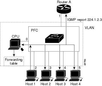
When a host connected to the switch wants to join an IP multicast group, it sends an unsolicited IGMP join message, specifying the IP multicast group to join. Alternatively, when the switch receives a general query from the router, it forwards the query to all ports in the VLAN. Hosts wanting to join the multicast group respond by sending a join message to the switch. The switch CPU creates a multicast forwarding-table entry for the group if it is not already present. The CPU also adds the interface where the join message was received to the forwarding-table entry. The host associated with that interface receives multicast traffic for that multicast group. See Figure 18-1.
Figure 18-1 Initial IGMP Join Message
Router A sends a general query to the switch, which forwards the query to ports 2 through 5, all members of the same VLAN. Host 1 wants to join multicast group 224.1.2.3 and multicasts an IGMP membership report (IGMP join message) to the group with the equivalent MAC destination address of 0x0100.5E01.0203. When the CPU receives the IGMP report multicast by Host 1, the CPU uses the information in the IGMP report to set up a forwarding-table entry, as shown in Table 18-1, that includes the port numbers of Host 1, the router, and the switch internal CPU.
Table 18-1 IGMP Snooping Forwarding Table
0100.5exx.xxxx
IGMP
0
0100.5e01.0203
!IGMP
1, 2
Note that the switch hardware can distinguish IGMP information packets from other packets for the multicast group.
•
•
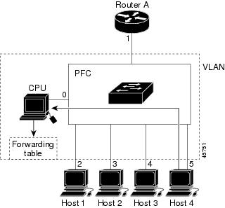
If another host (for example, Host 4) sends an unsolicited IGMP join message for the same group (Figure 18-2), the CPU receives that message and adds the port number of Host 4 to the forwarding table as shown in Table 18-2. Note that because the forwarding table directs IGMP messages to only the CPU, the message is not flooded to other ports on the switch. Any multicast traffic is forwarded to the group and not to the CPU.
Figure 18-2 Second Host Joining a Multicast Group
Table 18-2 Updated IGMP Snooping Forwarding Table
0100.5exx.xxxx
IGMP
0
0100.5e01.0203
!IGMP
1, 2, 5
Leaving a Multicast Group
The router sends periodic multicast general queries and the switch forwards these queries through all ports in the VLAN. Interested hosts respond to the queries. If at least one host in the VLAN wishes to receive multicast traffic, the router continues forwarding the multicast traffic to the VLAN. The switch forwards multicast group traffic to only those hosts listed in the forwarding table for that Layer 2 multicast group.
When hosts want to leave a multicast group, they can either silently leave, or they can send a leave message. When the switch receives a leave message from a host, it sends out a MAC-based general query to determine if any other devices connected to that interface are interested in traffic for the specific multicast group. The switch then updates the forwarding table for that MAC group so that only those hosts interested in receiving multicast traffic for the group are listed in the forwarding table. If the router receives no reports from a VLAN, it removes the group for the VLAN from its IGMP cache.
Immediate-Leave Processing
The switch uses IGMP snooping Immediate-Leave processing to remove from the forwarding table an interface that sends a leave message without the switch sending MAC-based general queries to the interface. The VLAN interface is pruned from the multicast tree for the multicast group specified in the original leave message. Immediate-Leave processing ensures optimal bandwidth management for all hosts on a switched network, even when multiple multicast groups are simultaneously in use.
Note
Configuring IGMP Snooping
IGMP snooping allows switches to examine IGMP packets and make forwarding decisions based on their content. To enable IGMP snooping on the switch to discover external multicast routers, the Layer 3 interfaces on the routers in the VLAN must already have been configured for multicast routing. For more information, see "Configuring IP Multicast Routing."
These sections describe how to configure IGMP snooping:
•
•
•
•
•
Default IGMP Snooping Configuration
Table 18-3 shows the default IGMP snooping configuration.
Enabling or Disabling IGMP Snooping
By default, IGMP snooping is globally enabled on the switch. When globally enabled or disabled, it is also enabled or disabled in all existing VLAN interfaces. IGMP snooping is by default enabled on all VLANs, but can be enabled and disabled on a per-VLAN basis. After you configure the VLAN interface for multicast routing, no configuration is needed for the switch to dynamically access external multicast routers by using IGMP snooping.
Global IGMP snooping overrides the VLAN IGMP snooping. If global snooping is disabled, you cannot enable VLAN snooping. If global snooping is enabled, you can enable or disable VLAN snooping.
Beginning in privileged EXEC mode, follow these steps to globally enable IGMP snooping on the switch:
To globally disable IGMP snooping on all VLAN interfaces, use the no ip igmp snooping global configuration command.
Beginning in privileged EXEC mode, follow these steps to enable IGMP snooping on a VLAN interface:
To disable IGMP snooping on a VLAN interface, use the no ip igmp snooping vlan vlan-id global configuration command for the specified VLAN number.
Setting the Snooping Method
Multicast-capable router ports are added to the forwarding table for every Layer 2 multicast entry. The switch learns of such ports through one of these methods:
•
•
•
You can configure the switch either to snoop on IGMP queries and PIM/DVMRP packets or to listen to CGMP self-join or proxy-join packets. By default, the switch snoops on PIM/DVMRP packets on all VLANs. To learn of multicast router ports through only CGMP packets, use the ip igmp snooping vlan vlan-id mrouter learn cgmp global configuration command. When this command is issued, the router listens to only CGMP self-join and CGMP proxy-join packets and no other CGMP packets. To learn of multicast router ports through only PIM-DVMRP packets, use the ip igmp snooping vlan vlan-id mrouter learn pim-dvmrp global configuration command.
Note
Beginning in privileged EXEC mode, follow these steps to alter the method in which a VLAN interface dynamically accesses a multicast router:
This example shows how to configure IGMP snooping to use CGMP packets as the learning method:
Switch# configure terminalSwitch(config)# ip igmp snooping vlan 1 mrouter learn cgmpSwitch(config)# endSwitch# show ip igmp snooping vlan 1vlan 1----------IGMP snooping is globally enabledIGMP snooping is enabled on this VlanIGMP snooping immediate-leave is disabled on this VlanIGMP snooping mrouter learn mode is cgmp on this VlanIGMP snooping is running in IGMP_ONLY mode on this VlanTo return to the default learning method, use the no ip igmp snooping vlan vlan-id mrouter learn cgmp global configuration command.
Configuring a Multicast Router Port
To add a multicast router port (add a static connection to a multicast router), use the ip igmp snooping vlan mrouter global configuration command on the switch.
Note
Beginning in privileged EXEC mode, follow these steps to enable a static connection to a multicast router:
To remove a multicast router port from the VLAN, use the no ip igmp snooping vlan vlan-id mrouter interface interface-id global configuration command.
This example shows how to enable a static connection to a multicast router and verify the configuration:
Switch# configure terminalSwitch(config)# ip igmp snooping vlan 200 mrouter interface gigabitethernet0/2Switch(config)# endSwitch# show ip igmp snooping mrouter vlan 200vlan ports-----+----------------------------------------200 Gi0/2(static)Configuring a Host Statically to Join a Group
Hosts or Layer 2 ports normally join multicast groups dynamically, but you can also statically configure a host on an interface.
Beginning in privileged EXEC mode, follow these steps to add a Layer 2 port as a member of a multicast group:
To remove the Layer 2 port from the multicast group, use the no ip igmp snooping vlan vlan-id static mac-address interface interface-id global configuration command.
This example shows how to statically configure a host on an interface and verify the configuration:
Switch# configure terminalSwitch(config)# ip igmp snooping vlan 1 static 0100.5e00.0203 interface gigabitethernet0/11Switch(config)# endSwitch# show mac-address-table multicast vlan 1Vlan Mac Address Type Ports---- ----------- ---- -----1 0100.5e00.0203 USER Gi0/11Enabling IGMP Immediate-Leave Processing
When you enable IGMP Immediate-Leave processing, the switch immediately removes a port when it detects an IGMP version 2 leave message on that port. You should use the Immediate-Leave feature only when there is a single receiver present on every port in the VLAN.
Immediate Leave is supported with only IGMP version 2 hosts.
Beginning in privileged EXEC mode, follow these steps to enable IGMP Immediate-Leave processing:
To disable IGMP Immediate-Leave on a VLAN, use the no ip igmp snooping vlan vlan-id immediate-leave global configuration command.
This example shows how to enable IGMP immediate-leave processing on VLAN 130 and verify the configuration:
Switch# configure terminalSwitch(config)# ip igmp snooping vlan 130 immediate-leaveSwitch(config)# endSwitch# show ip igmp snooping vlan 130vlan 130----------IGMP snooping is globally enabledIGMP snooping is enabled on this VlanIGMP snooping immediate-leave is enabled on this VlanIGMP snooping mrouter learn mode is pim-dvmrp on this VlanIGMP snooping is running in IGMP_ONLY mode on this VlanDisplaying IGMP Snooping Information
You can display IGMP snooping information for dynamically learned and statically configured router ports and VLAN interfaces. You can also display MAC address multicast entries for a VLAN configured for IGMP snooping.
To display IGMP snooping information, use one or more of the privileged EXEC commands in Table 18-4.
This is an example of output from the show ip igmp snooping privileged EXEC command for all VLAN interfaces on the switch:
Switch# show ip igmp snoopingvlan 1----------IGMP snooping is globally enabledIGMP snooping is enabled on this VlanIGMP snooping immediate-leave is disabled on this VlanIGMP snooping mrouter learn mode is pim-dvmrp on this VlanIGMP snooping is running in IGMP_ONLY mode on this Vlanvlan 2----------IGMP snooping is globally enabledIGMP snooping is enabled on this VlanIGMP snooping immediate-leave is disabled on this VlanIGMP snooping mrouter learn mode is pim-dvmrp on this VlanIGMP snooping is running in IGMP_ONLY mode on this Vlanvlan 10----------IGMP snooping is globally enabledIGMP snooping is enabled on this VlanIGMP snooping immediate-leave is disabled on this VlanIGMP snooping mrouter learn mode is pim-dvmrp on this VlanIGMP snooping is running in IGMP_ONLY mode on this VlanThis is an example of output from the show ip igmp snooping privileged EXEC command for a specific VLAN interface:
Switch# show ip igmp snooping vlan 1vlan 1----------IGMP snooping is globally enabledIGMP snooping is disabled on this VlanIGMP snooping immediate-leave is disabled on this VlanIGMP snooping mrouter learn mode is pim-dvmrp on this VlanThis is an example of output from the show ip igmp snooping mrouter privileged EXEC command:
Switch# show ip igmp snooping mroutervlan ports-----+----------------------------------------1 Gi0/1,Gi0/2,Router2 Gi0/3,Gi0/4This is an example of output from the show ip igmp snooping mrouter privileged EXEC command for VLAN 1:
Switch# show ip igmp snooping mrouter vlan 1Vlan ports---- -----1 Gi0/1(dynamic)1 Gi0/2(dynamic)This example shows how to display the Layer 2 multicast entries for VLAN 1:
Switch# show mac-address-table multicast vlan 1vlan mac address type ports-----+---------------+--------+---------+---+--------------------------------1 0100.5e02.0203 user Gi0/1,Gi0/21 0100.5e00.0127 igmp Gi0/1,Gi0/21 0100.5e00.0128 user Gi0/1,Gi0/21 0100.5e00.0001 igmp Gi0/1,Gi0/2This is an example of output from the show mac-address-table multicast count privileged EXEC command for the switch:
Switch# show mac-address-table multicast countMulticast MAC Entries for all vlans: 10This is an example of output from the show mac-address-table multicast count privileged EXEC command for a VLAN:
Switch# show mac-address-table multicast vlan 1 countMulticast MAC Entries for vlan 1:This example shows how to display only the user-configured multicast entries for VLAN 1:
Switch# show mac-address-table multicast vlan 1 uservlan mac address type ports-----+---------------+--------+---------+---+--------------------------------1 0100.5e02.0203 user Gi0/1,Gi0/21 0100.5e00.0128 user Gi0/1,Gi0/2This example shows how to display the total number of entries learned by IGMP snooping for VLAN 1:
Switch# show mac-address-table multicast vlan 1 igmp-snooping countNumber of user programmed entries: 2Understanding Multicast VLAN Registration
Multicast VLAN Registration (MVR) is designed for applications using wide-scale deployment of multicast traffic across an Ethernet ring-based service provider network (for example, the broadcast of multiple television channels over a service-provider network). MVR allows a subscriber on a port to subscribe and unsubscribe to a multicast stream on the network-wide multicast VLAN. It allows the single multicast VLAN to be shared in the network while subscribers remain in separate VLANs. MVR provides the ability to continuously send multicast streams in the multicast VLAN, but to isolate the streams from the subscriber VLANs for bandwidth and security reasons.
MVR assumes that subscriber ports subscribe and unsubscribe (join and leave) these multicast streams by sending out IGMP join and leave messages. These messages can originate from an IGMP version-2-compatible host with an Ethernet connection. Although MVR operates on the underlying mechanism of IGMP snooping, the two features operate independently of each other. One can be enabled or disabled without affecting the behavior of the other feature. However, if IGMP snooping and MVR are both enabled, MVR reacts only to join and leave messages from multicast groups configured under MVR. Join and leave messages from all other multicast groups are managed by IGMP snooping.
The switch CPU identifies the MVR IP multicast streams and their associated MAC addresses in the switch forwarding table, intercepts the IGMP messages, and modifies the forwarding table to include or remove the subscriber as a receiver of the multicast stream, even though the receivers might be in a different VLAN from the source. This forwarding behavior selectively allows traffic to cross between different VLANs.
The Catalyst 3550 switch has these modes of MVR operation: dynamic and compatible.
•
•
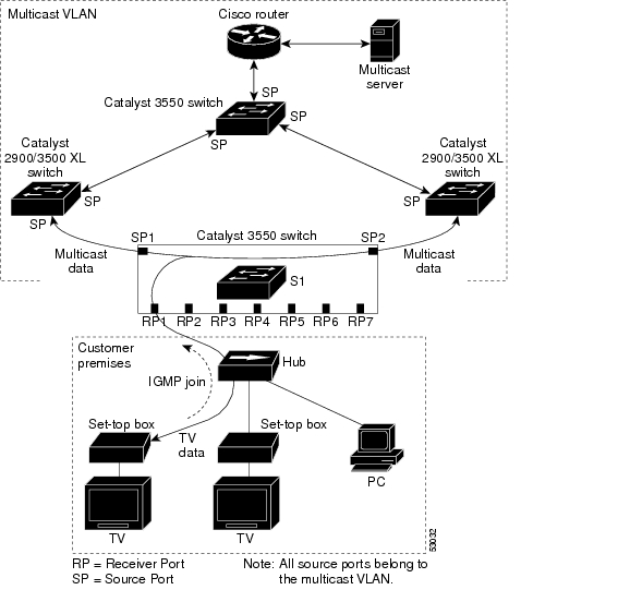
Using MVR in a Multicast Television Application
In a multicast television application, a PC or a television with a set-top box can receive the multicast stream. Multiple set-top boxes or PCs can be connected to one subscriber port, which is a switch port configured as an MVR receiver port. See Figure 18-3. DHCP assigns an IP address to the set-top box or the PC. When a subscriber selects a channel, the set-top box or PC sends an IGMP report to the S1 switch to join the appropriate multicast. If the IGMP report matches one of the configured multicast MAC addresses, the switch CPU modifies the hardware address table to include this receiver port and VLAN as a forwarding destination of the specified multicast stream when it is received from the multicast VLAN. Uplink ports that send and receive multicast data to and from the multicast VLAN are called MVR source ports.
When a subscriber changes channels or turns off the television, the set-top box sends an IGMP leave message for the multicast stream. The switch CPU sends an IGMP group-specific query through the receiver port VLAN. If there is another set-top box in the VLAN still subscribing to this group, that set-top box must respond within the maximum response time. If the CPU does not receive a response, it eliminates the receiver port as a forwarding destination for this group.
If the Immediate-Leave feature is enabled on a receiver port, the port leaves a multicast group more quickly. Without Immediate Leave, when the switch receives an IGMP leave message from a subscriber on a receiver port, it sends out an IGMP query on that port and waits for IGMP group membership reports. If no reports are received in a configured time period, the receiver port is removed from multicast group membership. With Immediate Leave, an IGMP query is not sent from the receiver port on which the IGMP leave was received. As soon as the leave message is received, the receiver port is removed from multicast group membership, which speeds up leave latency. Enable the Immediate Leave feature only on receiver ports to which a single receiver device is connected.
Figure 18-3 Multicast VLAN Registration Example
MVR eliminates the need to duplicate television-channel multicast traffic for subscribers in each VLAN. Multicast traffic for all channels is only sent around the VLAN trunk once—only on the multicast VLAN. Although the IGMP leave and join message in the VLAN to which the subscriber port is assigned. These messages dynamically register for streams of multicast traffic in the multicast VLAN on the Layer 3 device. The access layer switch (S1 switch) modifies the forwarding behavior to allow the traffic to be forwarded from the multicast VLAN to the subscriber port in a different VLAN, selectively allowing traffic to cross between two VLANs.
IGMP reports are sent to the same MAC addresses as the multicast data. The S1 CPU must capture all IGMP join and leave messages from receiver ports and forward them to the multicast VLAN of the source (uplink) port.
Configuring MVR
These sections include basic MVR configuration information:
•
•
Configuration Guidelines and Limitations
Follow these guidelines when configuring MVR:
•
•
•
•
Note
Default MVR Configuration
Table 18-5 shows the default MVR configuration.
Configuring MVR Global Parameters
You do not need to set the optional MVR parameters if you choose to use the default settings. If you do want to change the default parameters (except for the MVR VLAN), you must first enable MVR.
Beginning in privileged EXEC mode, follow these steps to configure MVR parameters:
To return the switch to its default settings, use the no mvr [mode | group ip-address | querytime | vlan] global configuration commands.
This example shows how to enable MVR, configure the MVR group address, set the query time to 1 second (10 tenths), specify the MVR multicast VLAN as VLAN 22, set the MVR mode as dynamic, and verify the results:
Switch(config)# mvrSwitch(config)# mvr group 228.1.23.4Switch(config)# mvr querytime 10Switch(config)# mvr vlan 22Switch(config)# mvr mode dynamicSwitch(config)# endSwitch# show mvrMVR Running: TRUEMVR multicast vlan: 22MVR Max Multicast Groups: 256MVR Current multicast groups: 1MVR Global query response time: 10 (tenths of sec)MVR Mode: dynamicYou can use the show mvr members privileged EXEC command to verify the MVR multicast group addresses on the switch.
Configuring MVR Interfaces
Beginning in privileged EXEC mode, follow these steps to configure MVR interfaces:
To return the interface to its default settings, use the no mvr [type | immediate | vlan vlan-id | group] interface configuration commands.
This example shows how to configure Gigabit Ethernet port 0/1 as a receiver port, statically configure the port to receive multicast traffic sent to the multicast group address, configure Immediate Leave on the interface, and verify the results.
Switch(config)# mvrSwitch(config)# interface gigabitethernet0/2Switch(config-if)# mvr type receiverSwitch(config-if)# mvr vlan 22 group 228.1.23.4Switch(config-if)# mvr immediateSwitch(config)# endSwitch# show mvr interface gigabitethernet0/2Type: RECEIVER Status: ACTIVE Immediate Leave: ENABLEDThis is an example of output from the show mvr interface privileged EXEC command when the member keyword is included:
Switch# show mvr interface gigabitethernet0/6 member239.255.0.0 DYNAMIC ACTIVE239.255.0.1 DYNAMIC ACTIVE239.255.0.2 DYNAMIC ACTIVE239.255.0.3 DYNAMIC ACTIVE239.255.0.4 DYNAMIC ACTIVE239.255.0.5 DYNAMIC ACTIVE239.255.0.6 DYNAMIC ACTIVE239.255.0.7 DYNAMIC ACTIVE239.255.0.8 DYNAMIC ACTIVE239.255.0.9 DYNAMIC ACTIVEDisplaying MVR Information
You can display MVR information for the switch or for a specified interface.
Beginning in privileged EXEC mode, use the commands in Table 18-6 to display MVR configuration:
This is an example of output from the show mvr privileged EXEC command:
Switch# show mvrMVR Running: TRUEMVR multicast vlan: 1MVR Max Multicast Groups: 256MVR Current multicast groups: 256MVR Global query response time: 5 (tenths of sec)MVR Mode: compatibleThis is an example of output from the show mvr interface privileged EXEC command:
Switch# show mvr interfacePort Type Status Immediate Leave---- ---- ------- ---------------Gi0/1 SOURCE ACTIVE/UP DISABLEDGi0/2 SOURCE ACTIVE/UP DISABLEDGi0/3 RECEIVER ACTIVE/UP DISABLEDGi0/4 RECEIVER ACTIVE/UP DISABLEDGi0/5 RECEIVER ACTIVE/UP ENABLEDGi0/6 RECEIVER ACTIVE/UP DISABLEDGi0/7 RECEIVER ACTIVE/UP ENABLEDGi0/8 RECEIVER ACTIVE/UP DISABLEDThis is an example of output from the show mvr interface privileged EXEC command for a specified interface:
Switch# show mvr interface gigabitethernet0/2Type: RECEIVER Status: ACTIVE Immediate Leave: DISABLEDThis is an example of output from the show mvr interface privileged EXEC command when the members keyword is included:
Switch# show mvr interface gigabitethernet0/6 members239.255.0.0 DYNAMIC ACTIVE239.255.0.1 DYNAMIC ACTIVE239.255.0.2 DYNAMIC ACTIVE239.255.0.3 DYNAMIC ACTIVE239.255.0.4 DYNAMIC ACTIVE239.255.0.5 DYNAMIC ACTIVE239.255.0.6 DYNAMIC ACTIVE239.255.0.7 DYNAMIC ACTIVE239.255.0.8 DYNAMIC ACTIVE239.255.0.9 DYNAMIC ACTIVEThis is an example of output from the show mvr members privileged EXEC command:
Switch# show mvr membersMVR Group IP Status Members------------ ------ -------239.255.0.1 ACTIVE Gi0/1(d), Gi0/5(s)239.255.0.2 INACTIVE None239.255.0.3 INACTIVE None239.255.0.4 INACTIVE None239.255.0.5 INACTIVE None239.255.0.6 INACTIVE None239.255.0.7 INACTIVE None239.255.0.8 INACTIVE None239.255.0.9 INACTIVE None239.255.0.10 INACTIVE None<output truncated>239.255.0.255 INACTIVE None239.255.1.0 INACTIVE NoneConfiguring IGMP Filtering
In some environments, for example metropolitan or multiple-dwelling unit (MDU) installations, an administrator might want to control the set of multicast groups to which a user on a switch port can belong. This allows the administrator to control the distribution of multicast services, such as IP/TV, based on some type of subscription or service plan. With the IGMP filtering feature, you can filter multicast joins on a per-port basis by configuring IP multicast profiles and associating them with individual switch ports. An IGMP profile can contain one or more multicast groups and specifies whether access to the group is permitted or denied. If an IGMP profile denying access to a multicast group is applied to a switch port, the IGMP join report requesting the stream of IP multicast traffic is dropped, and the port is not allowed to receive IP multicast traffic from that group. If the filtering action permits access to the multicast group, the IGMP report from the port is forwarded for normal processing.
IGMP filtering controls only IGMP membership join reports and has no relationship with the function that directs the forwarding of IP multicast traffic. The filtering feature operates in the same manner whether CGMP or MVR is used to forward the multicast traffic.
You can also set the maximum number of IGMP groups that a Layer 2 interface can join.
Default IGMP Filtering Configuration
Table 18-5 shows the default IGMP filtering configuration.
Configuring IGMP Profiles
To configure an IGMP profile, use the ip igmp profile global configuration command with a profile number to create an IGMP profile and to enter IGMP profile configuration mode. From this mode, you can specify the parameters of the IGMP profile to be used for filtering IGMP join requests from a port. When you are in IGMP profile configuration mode, you can create the profile by using these commands:
•
•
•
•
•
The default is for the switch to have no IGMP profiles configured. When a profile is configured, if neither the permit nor deny keyword is included, the default is to deny access to the range of IP addresses.
Beginning in privileged EXEC mode, follow these steps to create an IGMP profile:
To delete a profile, use the no ip igmp profile profile number global configuration command.
To delete an IP multicast address or range of IP multicast addresses, use the no range ip multicast address IGMP profile configuration command.
This example shows how to create IGMP profile 4 allowing access to the single IP multicast address and how to verify the configuration. If the action was to deny (the default), it would not appear in the show ip igmp profile output display.
Switch # config tSwitch(config) # ip igmp profile 4Switch(config-igmp-profile)# permitSwitch(config-igmp-profile)# range 229.9.9.0Switch(config-igmp-profile)# endSwitch# show ip igmp profile 4IGMP Profile 4permitrange 229.9.9.0 229.9.9.0Applying IGMP Profiles
To control access as defined in an IGMP profile, use the ip igmp filter interface configuration command to apply the profile to the appropriate interfaces. You can apply IGMP profiles to Layer 2 ports only; you cannot apply IGMP profiles to routed ports or SVIs. You cannot apply profiles to ports that belong to an EtherChannel port group. You can apply a profile to multiple interfaces, but each interface can only have one profile applied to it.
Beginning in privileged EXEC mode, follow these steps to apply an IGMP profile to a switch port:
To remove a profile from an interface, use the no ip igmp filter profile number interface configuration command.
This example shows how to apply IGMP profile 4 to an interface and verify the configuration.
Switch # config tSwitch(config)# interface fastethernet0/12Switch(config-if)# ip igmp filter 4Switch(config-if)# endSwitch# show running-config interface fastethernet0/12Building configuration...Current configuration : 123 bytes!interface FastEthernet0/12no ip addressshutdownsnmp trap link-statusip igmp max-groups 25ip igmp filter 4endSetting the Maximum Number of IGMP Groups
You can set the maximum number of IGMP groups that a Layer 2 interface can join by using the ip igmp mac-groups interface configuration command. Use the no form of this command to set the maximum back to the default, which is no limit.
This restriction can be applied to Layer 2 ports only; you cannot set a maximum number of IGMP groups on routed ports or SVIs. You also cannot use this command on ports that belong to an EtherChannel port group.
Beginning in privileged EXEC mode, follow these steps to apply an IGMP profile to a switch port:
To remove the maximum group limitation and return to the default of no maximum, use the no ip igmp max-groups interface configuration command.
This example shows how to limit the number of IGMP groups that an interface can join to 25.
Switch# config tSwitch(config)# interface fastethernet0/12Switch(config-if)# ip igmp max-groups 25Switch(config-if)# endSwitch# show running-config interface fastethernet0/12Building configuration...Current configuration : 123 bytes!interface FastEthernet0/12no ip addressshutdownsnmp trap link-statusip igmp max-groups 25ip igmp filter 4endDisplaying IGMP Filtering Configuration
You can display IGMP profile characteristics, and you can display the IGMP profile and maximum group configuration for all interfaces on the switch or for a specified interface.
Use the privileged EXEC commands in Table 18-8 to display IGMP filtering configuration:
This is an example of the show ip igmp profile privileged EXEC command when no profile number is entered. All profiles defined on the switch are displayed.
Switch# show ip igmp profileIGMP Profile 3range 230.9.9.0 230.9.9.0IGMP Profile 4permitrange 229.9.9.0 229.255.255.255This is an example of the output from the show running-config privileged EXEC command when an interface is specified with IGMP maximum groups configured and IGMP profile 4 has been applied to the interface.
Switch# show running-config interface fastethernet0/12Building configuration...Current configuration : 123 bytes!interface FastEthernet0/12no ip addressshutdownsnmp trap link-statusip igmp max-groups 25ip igmp filter 4end