-
Catalyst 2948G-L3 and Catalyst 4908G-L3 Software Feature and Configuration Guide IOS Software, Release 12.0(10)W5(18e)
-
Preface
-
Overview of Layer 3 Switching and Software Features
-
Before You Begin
-
Initial Switch Router Configurations
-
Configuring Interfaces
-
Configuring Virtual LAN Encapsulation
-
Configuring Networking Protocols
-
Configuring Bridging
-
Configuring Etherchannel
-
Configuring Quality of Service
-
Configuring Switching Database Manager
-
Configuring Access Control Lists
-
Command Reference
-
Error Messages
-
Configuration Examples
-
Cisco IOS Commands Not Supported in Layer 3 Switching Software
-
Using Technical Support
-
 Feedback
Table Of Contents
Configuring Virtual LAN Encapsulation
Configuring ISL VLAN Encapsulation
Configuring 802.1Q VLAN Encapsulation
Configuring 802.1Q VLAN Bridging
Monitoring and Verifying VLAN Operation
Configuring Virtual LAN Encapsulation
This chapter describes virtual LAN (VLAN) configurations for the Layer 3 switch router. It describes how to configure Inter-Switch Link (ISL) VLAN encapsulation and how to configure 802.1Q VLAN encapsulation. For more information about the Cisco IOS commands used in this chapter, refer to the Cisco IOS Command Reference publication. This chapter contains the following sections:
•
Configuring ISL VLAN Encapsulation
•
•
•
Note
(see the "Suggested Process for Configuring the Layer 3 Switch Routers" section). This is an optional step. You should have already completed general interface configurations before proceeding with configuring VLANs as an optional step.
Understanding VLANs
VLANs enable network managers to group users logically rather than by physical location. A VLAN is an emulation of a standard LAN that allows data transfer and communication to occur without the traditional restraints placed on the network. It can also be considered a broadcast domain set up within a switch. With VLANs, switches can support more than one subnet (or VLAN) on each switch, and give routers and switches the opportunity to support multiple subnets on a single physical link. A group of devices that belong to the same VLAN, but are part of different LAN segments, are configured to communicate as if they were part of the same LAN segment. Layer 3 switching supports up to
244 VLAN subinterfaces per system.VLANs enable efficient traffic separation and provide excellent bandwidth utilization. VLANs also alleviate scaling issues by logically segmenting the physical LAN structure into different subnetworks so that packets are switched only between ports within the same VLAN. This can be very useful for security, broadcast containment, and accounting.
Layer 3 switching software supports a port-based VLAN on a trunk port, which is a port that carries the traffic of multiple VLANs. Each frame transmitted on a trunk link is tagged as belonging to only one VLAN.
Layer 3 switching software supports VLAN frame encapsulation through the Inter-Switch Link (ISL) protocol and the 802.1Q standard on both the Catalyst 2948G-L3 and the Catalyst 4908G-L3 switch routers.
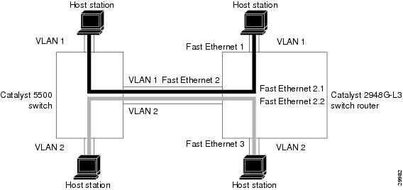
Figure 5-1 shows a network topology where two VLANs span a Catalyst 5500 switch and a Catalyst 2948G-L3 switch router. Both VLANs in this topology are bridged using the ISL protocol.
Figure 5-1 VLANs Spanning Devices in a Network
Note
Configuring ISL VLAN Encapsulation
ISL is a Cisco protocol for interconnecting multiple switches and maintaining VLAN information as traffic travels between switches.
You can configure VLAN encapsulation on both the Catalyst 2948G-L3 and the Catalyst 4908G-L3 switch routers. The VLAN configuration example for the Catalyst 2948G-L3 switch router in Figure 5-2 shows the following:
•
•
Figure 5-2 Example of an ISL VLAN Bridging Configuration
Note
To configure the ISL VLANs, perform the following task beginning in global configuration mode:
The following example shows how to configure the interfaces for VLAN bridging with ISL encapsulation shown in Figure 5-2:
Router(config)# interface fastethernet 2.1Router(config-subif)# encap isl 50Router(config-subif)# bridge-group 1Router(config-subif)# interface fastethernet 1Router(config-if)# bridge-group 1Router(config-if)# exitRouter(config)# bridge 1 protocol ieeeRouter(config)# interface fastethernet 2.2Router(config-subif)# encap isl 100Router(config-subif)# bridge-group 2Router(config-subif)# interface fastethernet 2Router(config-if)# bridge-group 2Router(config-if)# exitRouter(config)# bridge 2 protocol ieeeRouter(config)# endRouter# copy running-config startup-configTo monitor the VLANs once they are configured, see the "Monitoring and Verifying VLAN Operation" section.
Configuring 802.1Q VLAN Encapsulation
On an 802.1Q trunk port, all transmitted and received frames are tagged except for those on the VLAN configured as the native VLAN for the port. Frames on the native VLAN are always transmitted untagged and are normally received untagged.
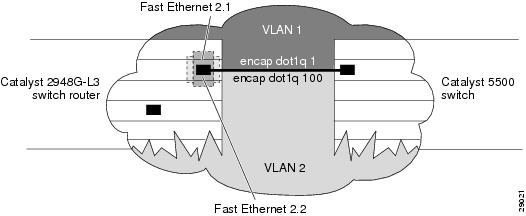
You can configure VLAN encapsulation on both the Catalyst 2948G-L3 and the Catalyst 4908G-L3 switch routers. The VLAN configuration example for the Catalyst 2948G-L3 switch router shown in Figure 5-3 depicts the following:
•
•
Figure 5-3 Example of Routing Between 802.1Q VLANs
Note
To configure VLANs for routing using 802.1Q VLAN encapsulation, perform the following task beginning in global configuration mode:
The following example shows how to configure VLANs for routing using 802.1Q VLAN encapsulation shown in Figure 5-3:
Router(config)# interface fastethernet 2.1Router(config-subif)# encap dot1q 1 nativeRouter(config-subif)# ip address 10.1.2.3 255.0.0.0Router(config-subif)# exitRouter(config)# interface fastethernet 2.2Router(config-subif)# encap dot1q 2Router(config-subif)# ip address 10.1.2.3 255.0.0.1Router(config-subif)# endRouter# copy running-config startup-config
Note
Configuring 802.1Q VLAN Bridging
802.1Q VLAN bridging is a protocol for interconnecting multiple switches and maintaining VLAN information as traffic travels between switches.
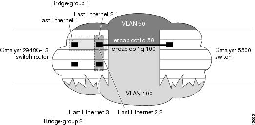
You can configure VLAN bridging on both the Catalyst 2948G-L3 and the Catalyst 4908G-L3 switch routers. The VLAN configuration example for the Catalyst 2948G-L3 in Figure 5-4 shows the following:
•
•
Figure 5-4 Example of an ISL VLAN Bridging Configuration
Note
To configure the 802.1Q bridging VLANs, perform the following task beginning in global configuration mode:
The following example shows how to configure the interfaces for VLAN bridging with 802.1Q bridging shown in Figure 5-4:
Router(config)# interface fastethernet 2.1Router(config-subif)# encap dot1q 50 nativeRouter(config-subif)# bridge-group 1Router(config-subif)# interface fastethernet 1Router(config-if)# bridge-group 1Router(config-if)# exitRouter(config)# bridge 1 protocol ieeeRouter(config)# interface fastethernet 2.2Router(config-subif)# dot1q 100Router(config-subif)# bridge-group 2Router(config-subif)# interface fastethernet 2Router(config-if)# bridge-group 2Router(config-if)# exitRouter(config)# bridge 2 protocol ieeeRouter(config)# endRouter# copy running-config startup-configTo monitor the VLANs once they are configured, see the "Monitoring and Verifying VLAN Operation" section.
Monitoring and Verifying VLAN Operation
After the VLANs are configured on the Layer 3 switch router, you can monitor their operation by performing the following task:
Router# show vlan vlan-id
Display information on all configured VLANs or on a specific VLAN (by VLAN ID number).
To configure encapsulation over the EtherChannel, see the "Understanding Encapsulation over EtherChannel" section.