-
Catalyst 2948G-L3 and Catalyst 4908G-L3 Software Feature and Configuration Guide IOS Software, Release 12.0(10)W5(18e)
-
Preface
-
Overview of Layer 3 Switching and Software Features
-
Before You Begin
-
Initial Switch Router Configurations
-
Configuring Interfaces
-
Configuring Virtual LAN Encapsulation
-
Configuring Networking Protocols
-
Configuring Bridging
-
Configuring Etherchannel
-
Configuring Quality of Service
-
Configuring Switching Database Manager
-
Configuring Access Control Lists
-
Command Reference
-
Error Messages
-
Configuration Examples
-
Cisco IOS Commands Not Supported in Layer 3 Switching Software
-
Using Technical Support
-
 Feedback
Table Of Contents
Understanding Layer 3 Switching
Layer 3 Switch Router Interface Types
Layer 3 Switching Software Features
Distributed Hardware Forwarding
Integrated Routing and Bridging
IEEE 802.1Q VLAN Encapsulation
Inter-Switch Link VLAN Encapsulation
Overview
This chapter provides an overview of the Catalyst 2948G-L3 and the Catalyst 4908G-L3 switch router interface types, and shows how these Layer 3 switch routers fit into the network. Also included is a list of Layer 3 switching software features with brief descriptions of selected features. This chapter contains the following sections:
•
Understanding Layer 3 Switching
•
•
•
Understanding Layer 3 Switching
A Layer 3 switch router refers to a high-performance router optimized for the campus LAN or intranet, providing both wirespeed Ethernet routing and switching services. Layer 3 switch routers improve network performance with two software functions—route processing and intelligent network services.
Compared to conventional software-based routers, Layer 3 switch routers process more packets faster by using application-specific integrated circuit (ASIC) hardware instead of microprocessor-based engines.
Layer 3 Switch Router Interface Types
Both the Catalyst 2948G-L3 and the Catalyst 4908G-L3 switch routers have fixed configurations based on Layer 3 switching software. The Catalyst 2948G-L3 switch router is a multiprotocol 10/100/1000 Ethernet switch router and the Catalyst 4908G-L3 switch router is a multiprotocol Gigabit Ethernet switch router.
Table 1-1 lists the interfaces supported in the Layer 3 switch routers.
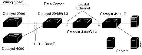
Network Configuration Example
Figure 1-1 shows how the Layer 3 switch routers are used in a small campus backbone.
Figure 1-1 Layer 3 Switch Routers in a Small Campus Backbone
Layer 3 Switching Software Features
This section lists the switching software features on the Catalyst 2948G-L3 and the Catalyst 4908G-L3 switch routers.
•
–
–
•
–
–
–
–
–
–
–
–
–
–
•
–
–
–
–
–
–
–
–
–
–
•
–
–
–
–
–
–
–
–
–
–
•
–
–
–
–
–
–
–
Note
•
–
–
–
–
–
–
–
•
–
–
–
–
•
–
–
•
–
–
–
–
–
–
–
–
–
–
Understanding Key Features
This section describes the key features supported in Layer 3 switching software.
Distributed Hardware Forwarding
Layer 3-switching software employs a distributed architecture in which the control path and data path are relatively independent. The control path code, such as routing protocols, runs on the processor; the data packets are switched by the Ethernet interfaces and the switching fabric.
A microcoded application-specific integrated circuit (ASIC) handles all packet switching for the interfaces. The following are the main functions of the control layer between the routing protocol and the firmware data path microcode:
•
•
•
•
Cisco IOS Routing Protocols
Layer 3-switching software provides a comprehensive suite of routing protocols based on Cisco IOS software. The following networking protocols and routing protocols are supported on the Layer 3 switch routers.
IP
RIP, RIP-2, OSPF, IGRP, EIGRP, PIM, BGP
IPX
IPX RIP, EIGRP
Many of the Cisco IOS routing protocol features, such as route redistribution and load balancing over equal cost paths (for OSPF and EIGRP) are supported. Configuration of these routing protocols is identical to the configuration methods currently employed on all Cisco routers.
Note
For more information on configuring network protocols see "Configuring Networking Protocols."
Caution
QoS-Based Forwarding
Quality of service (QoS) includes technologies such as Resource ReSerVation Protocol (RSVP), weighted round-robin (WRR), policing, and shaping, which help control bandwidth, network delay, jitter, and packet loss in networks that become congested. The QoS identifier provides specific treatment to traffic in different classes, so that each class receives different quality of service.
The class to which the packets belong determine packet scheduling and discarding policies. For example, the overall service given to packets in the premium class will be better than that given to the standard class; the premium class is expected to experience lower loss rate or delay.
The switch router has QoS-based forwarding for IP traffic only. The implementation of QoS forwarding is based on local administrative policy and IP precedence. The mapping between the IP precedence field and the QoS field determines the delay priority of the packet.
For more information about QoS see "Configuring Quality of Service."
Caution
Network Class Redundancy
The redundancy of Cisco IOS software provides key network features, such as Hot Standby Router Protocol (HSRP), routing protocol convergence with Routing Information Protocol (RIP), Open Shortest Path First (OSPF), Enhanced Interior Gateway Routing Protocol (EIGRP), EtherChannel, and load sharing across equal cost Layer 3 paths and spanning trees (for Layer 2-based networks).
Remote Monitoring
Layer 3 switching software supports the first four remote monitoring (RMON) groups.
RMON is a network management protocol for gathering network information and monitoring traffic data within remote LAN segments from a central location. RMON allows you to monitor all nodes and their interaction on a LAN segment. RMON, used with the SNMP agent in the switch router, allows you to view both the traffic that flows through the router and segment traffic not necessarily destined for the switch router. Layer 3-switching software combines RMON alarms and events with existing MIBs so you can choose where monitoring will occur.
Refer to the Cisco IOS Configuration Fundamentals Configuration Guide for more information about RMON.
Load Balancing
A switch router that employs load balancing can distribute traffic over all its network ports that are the same distance from the destination address. Load balancing increases the utilization of network segments and increases effective network bandwidth.
Layer 3-switching software uses source + destination-based load balancing, an enhanced version of the Cisco IOS software per-destination load balancing. This method takes certain bits from the source and destination IP and IPX addresses and maps them into a path.
This method has these benefits:
•
•
Layer 3-switching software supports load balancing on two equal cost paths using the source and destination IP or IPX address. Per-packet load balancing is not supported.
Cisco Discovery Protocol
Cisco Discovery Protocol (CDP) is a device-discovery protocol that is both media and protocol independent. CDP is available on all Cisco products, including routers, switches, bridges, and access servers. Using CDP, a device can advertise its existence to other devices and receive information about other devices on the same LAN. CDP enables Cisco products to exchange information with each other regarding their MAC addresses, IP addresses, and outgoing interfaces. CDP runs over the data link layer only, which allows two systems that support different network-layer protocols to learn about each other. Each device configured for CDP sends periodic messages to a multicast address. Each device advertises at least one address at which it can receive Simple Network Management Protocol (SNMP) messages.
Cisco Express Forwarding
Layer 3-switching software features Cisco Express Forwarding (CEF). CEF is advanced Layer 3 IP-switching technology. CEF optimizes network performance and scalability for networks with large and dynamic traffic patterns, such as the Internet, on networks characterized by intensive Web-based applications, or interactive sessions. Although you can use CEF in any part of a network, it is designed for high-performance, highly resilient Layer 3 IP-backbone switching.
CEF manages route distribution and forwarding by distributing routing information from the central processor to the individual Ethernet interfaces. This technology, used within the Internet, provides scalability in large campus core networks. CEF provides Layer 3 forwarding based on a topology map of the entire network, resulting in high-speed routing table lookups and forwarding.
One of the key benefits of CEF in Layer 3 switching is its routing convergence. Because the forwarding information base (FIB) is distributed to all interfaces, whenever a route goes away or is added, the FIB updates that information and provides it to the interfaces. Central processor interrupts are minimized. The interfaces receive the new topology very quickly and reconverge around a failed link based on the routing protocol being used.
Caution
Hot Standby Router Protocol
The Hot Standby Router Protocol (HSRP) provides high network availability by routing IP traffic from hosts on Ethernet networks without relying on the availability of any single switch router. This feature is particularly useful for hosts that do not support a router discovery protocol and do not have the functionality to switch to a new router when their selected router reloads or loses power.
Devices that are running the HSRP detect a failure by sending and receiving multicast User Datagram Protocol (UDP) "hello" packets. When HSRP detects that the designated active router has failed, the selected backup router assumes control of the HSRP group's MAC and IP addresses. (You can also select a new standby router at that time.)
The chosen MAC address and IP addresses are unique and do not conflict with any others on the same network segment. The MAC address is selected from a pool of Cisco MAC addresses. Configure the last byte of the MAC address by configuring the HSRP group number. You also configure the unique virtual IP address. The IP address must be specified on a single router within the same group. When the HSRP is running, it selects an active router and instructs its device layer to listen on an additional (dummy) MAC address.
Layer 3-switching software supports HSRP over 10/100 Ethernet, Gigabit Ethernet, FEC, GEC, and BVI.
Fast EtherChannel
Fast EtherChannel (FEC) establishes a high-bandwidth connection between two Layer 3-switch devices. You can use up to four FEC connections as one Layer 3-forwarding path, which can provide up to an 800-Mbps full-duplex aggregate capacity. If link detection determines a failure of any one link, the packets are switched on the remaining active links in the FEC. No dependencies are placed on which ports to configure in the channel.
FEC uses a source-destination IP and IPX address load-balancing scheme for up to four ports in a channel group. Each channel group has its own IP and IPX address.When you queue a packet to exit out of the port channel interface, the last two bits of the IP and IPX source and destination address determine which interface in the channel the packet takes.
For more information about FEC see "Configuring EtherChannel."
Gigabit EtherChannel
Gigabit EtherChannel (GEC) allows grouping of gigabit ports into a single multigigabit logical EtherChannel link. GEC establishes a high-bandwidth connection between two Catalyst switch routers.
You can bundle up to two Gigabit Ethernet connections on the Catalyst 2948G-L3 switch router as one logical link, which can provide up to 4-Gb full-duplex aggregate capacity. On the Catalyst 4908G-L3 switch router, you can bundle up to four Gigabit Ethernet connections, which provide up to 8-Gb full-duplex aggregate capacity. If a failure of any one link is detected, the packets are switched on the remaining active link in the GEC.
GEC uses a source-destination IP and IPX address load-balancing scheme for up to two ports in a channel group on the Catalyst 2948G-L3 switch router and up to four ports in a channel group on the Catalyst 4908G-L3 switch router. Each channel group has its own IP address.When you queue a packet to exit out of the port channel interface, the last two bits of the IP source and destination address determine which interface in the channel the packet takes.
As with all EtherChannel technologies, all links share the traffic load within the bundled ports.
For more information about GEC, see "Configuring EtherChannel."
Integrated Routing and Bridging
Integrated Routing and Bridging (IRB) allows you to route a given protocol between routed interfaces and various bridge groups or between bridge groups within a single router. Multiple ports in the switch router can reside in one bridge group with one IP address and be routed to other switch router interfaces with different IP addresses.
Specifically, you bridge local or unroutable traffic among the bridged interfaces in the same bridge group, while you route routable traffic to other routed interfaces or bridge groups.
Layer 3-switching software supports IRB for IP and IPX only.
Here are some examples of when to use IRB:
•
For example, when you are migrating a bridged network to a routed network, or when the remote site does not have routing capabilities, you can use the switch router to interconnect the bridged and routed networks.
•
•
Note
24K CAM on the Catalyst 2948G-L3 switch router and the 32K CAM on the Catalyst 4908G-L3 switch router.For more information about IRB, see the "Configuring IRB" section.
Spanning Tree Protocol
The Spanning Tree Protocol (STP) is a bridge protocol that enables a learning bridge to dynamically work around loops in a network topology by creating a spanning tree. Bridges exchange bridge protocol data unit (BPDU) messages with other bridges to detect loops, and then remove the loops by shutting down selected bridge interfaces.
STP maintains a network of multiple bridges or switches. When the topology changes, the STP transparently reconfigures bridges and switches to avoid the creation of loops by placing ports in a forwarding or blocking state. Each bridge group has a separate instance of the STP.
STP parameters are set for each bridge group. For each spanning tree instance, you configure a set of global options with a set of port parameters. The port parameter list contains only ports that are members of a given bridge group. The Layer 3 switch routers support a maximum of 16 bridge groups, which run their own instance of spanning tree.
Virtual LANs
A VLAN configures switches and routers according to logical rather than physical topologies. Using VLANs, a network administrator can combine any collection of LAN segments within an internetwork into an autonomous user group, which appears as a single LAN. VLANs logically segment the network into different broadcast domains so that packets are switched only between ports within the VLAN. Typically, a VLAN corresponds to a particular subnet, although not necessarily.
To configure VLANs, you first define a subinterface at the interface, and map a VLAN to the subinterface. Layer 3-switching software supports up to 244 VLAN subinterfaces per system and up to 32 VLAN subinterfaces per physical port.
For more information about VLANs, see the "Understanding VLANs" section.
IEEE 802.1Q VLAN Encapsulation
IEEE 802.1Q provides a method for secure bridging of data across a shared backbone.
Layer 3-switching software supports 802.1Q VLAN encapsulation over all media including Fast Ethernet, Gigabit Ethernet, FEC, and GEC. The switch router can route between 802.1Q and ISL trunks.802.1Q encapsulation uses an internal, or one level, packet tagging scheme to multiplex VLANs across a single physical link, while maintaining strict adherence to the individual VLAN domains. 802.1Q can have access ports or untagged ports where frames are assigned to VLANs based on a port VLAN identifier (PVID), or native VLAN for the port. It can also have trunked ports where some frames can be tagged and others untagged. 802.1Q uses Per VLAN Spanning Tree Plus (PVST+), mapping multiple spanning trees to the spanning tree of pure 802.1Q switches.
For more information about 802.1Q, see the "Configuring 802.1Q VLAN Encapsulation" section.
Inter-Switch Link VLAN Encapsulation
Layer 3-switching software also supports Inter-Switch Link (ISL) encapsulation over all media, including Fast Ethernet, Gigabit Ethernet, FEC, and GEC. The switch router can be deployed in environments with the ISL trunking protocol, and can route between ISL and 802.1Q stations.
ISL encapsulation uses an external, or two level, packet tagging scheme to multiplex VLANs across a single physical link, while maintaining strict adherence to the individual VLAN domains. With ISL, all packets must be tagged on a physical link.
ISL uses one PVST over ISL trunks.
For more information about ISL, see the "Configuring ISL VLAN Encapsulation" section.
Switching Database Manager
Layer 3-switching software features the switching database manager (SDM). SDM resides on the central processor and its primary function is to maintain the Layer 3-switching database in ternary content addressable memory (TCAM). SDM maintains the address entries contained in TCAM in an appropriate order. SDM manages TCAM space by partitioning protocol-specific switching information into multiple regions.
The key benefit of SDM in Layer 3 switching is its ability to configure the size of the protocol regions in TCAM. SDM enables exact-match and longest-match address searches, which result in high-speed forwarding.
For more information about SDM, see "Configuring Switching Database Manager."
Access Control Lists
ACLs provide a tool for network control and security, allowing you to filter packet flow into or out of switch router interfaces. ACLs are sometimes called filters. You can use ACLs to restrict network use by certain users or devices. ACLs are created for each protocol and applied on the interface either for inbound or outbound traffic. They can be configured for all routed network protocols (IP or Novell IPX) to filter packets for the protocol as they pass through a switch router. Only one ACL can be applied per protocol per (sub)interface in each direction.
When creating ACLs, you define criteria to apply to each packet processed by the switch router; the switch router decides whether to forward or block the packet based on whether or not the packet matches the criteria in your list. Packets that do not match any criteria in your list are automatically blocked by the implicit "deny all traffic" criteria statement at the end of every access list.
The specific instructions for creating ACLs and applying them to interfaces vary from protocol to protocol. Configuration of Layer 3-switching ACLs is identical to the configuration methods currently employed on all Cisco routers.
ACL functionality is built into Gigabit Ethernet ports of the Catalyst 2948G-L3 and 4908G-L3 switch router. However, ACLs are not supported on Fast Ethernet ports, BVI, FEC, or GEC. For a list of supported ACLs, see the "Access Control List (ACL) Features" section.
Traffic that is switched by interface modules does not support ACL logging. However, ACL logging is supported for all traffic that goes to the CPU.
The enhanced Gigabit Ethernet interface module supports TCAM size of 32K (32-bit) entries. The combined size of the protocol regions and access lists should not exceed your TCAM space. The default size of the access lists in a 32K TCAM is 512 (128-bit) entries. Before you configure the access list, make sure that TCAM has enough space to accommodate the access list.
IEEE 802.1Q VLAN Bridging
Layer 3-switching software also supports 802.1Q bridging over all media, including Fast Ethernet, Gigabit Ethernet, FEC, and GEC. The switch router can be deployed in environments with the 802.1Q trunking protocol and can bridge between ISL and 802.1Q stations.
For more information about 802.1Q VLAN bridging, see the "Configuring 802.1Q VLAN Bridging" section.
IP Uplink Redirect
IP uplink redirect enables traffic between Fast Ethernet interfaces to be switched through the Gigabit Ethernet interface. ACLs can be applied on the Gigabit Ethernet interface to filter traffic switched between Fast Ethernet interfaces. IP uplink redirect is supported on the Catalyst 2948G-L3 switch router only.