-
Catalyst 2948G-L3 and Catalyst 4908G-L3 Software Feature and Configuration Guide IOS Software, Release 12.0(10)W5(18e)
-
Preface
-
Overview of Layer 3 Switching and Software Features
-
Before You Begin
-
Initial Switch Router Configurations
-
Configuring Interfaces
-
Configuring Virtual LAN Encapsulation
-
Configuring Networking Protocols
-
Configuring Bridging
-
Configuring Etherchannel
-
Configuring Quality of Service
-
Configuring Switching Database Manager
-
Configuring Access Control Lists
-
Command Reference
-
Error Messages
-
Configuration Examples
-
Cisco IOS Commands Not Supported in Layer 3 Switching Software
-
Using Technical Support
-
 Feedback
Table Of Contents
How System Error Messages are Organized
How to Read System Error Messages
Error Message Traceback Reports
System Error Messages
This appendix lists and describes the system error messages for the Layer 3 switch routers. The system software sends these error messages to the console (and, optionally, to a logging server on another system) during operation. Not all system error messages indicate problems with your system. Some are purely informational, while others may help diagnose problems with communications lines, internal hardware, or the system software. This appendix contains the following sections:
•
How System Error Messages are Organized
•
•
Note
How System Error Messages are Organized
System error messages are organized according to the particular system facility that produces the messages. The facility sections appear in alphabetical order, and within each system facility section, messages are listed alphabetically by mnemonic. An explanation and a recommended action follow each error message. System error messages appear only when the system remains operational.
Error message severity levels correspond to the keywords assigned by the logging global configuration commands that define where and at what level these messages appear. The default is to log messages to the console at the debugging level (7).
How to Read System Error Messages
This section describes how system error messages are structured.
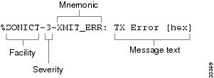
System error messages begin with a percent sign and are structured as follows:
%FACILITY-SEVERITY-MNEMONIC: Message-textFacility is a code consisting of two or more uppercase letters that indicate the facility to which the message refers. A facility can be a hardware device, a protocol, or a module of the system software. Table B-1 lists the system facility codes.
Severity is a single-digit code from 0 to 7 that reflects the severity of the condition. The lower the number, the more serious the situation. Table B-2 lists the severity levels.
Mnemonic is a code that uniquely identifies the error message.
Message-text is a text string describing the condition. This portion of the message sometimes contains detailed information about the event, including terminal port numbers, network addresses, or addresses that correspond to locations in the system memory address space. Because the information in these variable fields changes from message to message, it is represented here by short strings enclosed in square brackets ([ ]). A decimal number, for example, is represented as [dec]. Table B-3 lists the representations of variable fields and the type of information in them.
Table B-3 Representation of Variable Fields in Error Messages
[dec]
Decimal number
[hex]
Hexadecimal number
[char]
Single character
[chars]
Character string
Figure B-1 describes the structure of a sample system error message.
Figure B-1 Structure of a Sample System Error Message
Error Message Traceback Reports
Some messages describe internal errors and contain traceback information. This information is very important and should be included when you report a problem to your technical support representative.
The following sample message includes traceback information:
-Process= "Exec", level= 0, pid= 17-Traceback= 1A82 1AB4 6378 A072 1054 1860Error Messages
This section describes error messages for the Catalyst 2948G-L3 and the Catalyst 4908G-L3 switch routers.
•
For example, if the number of IP multicast routes added to SDM exceeds the size configured with the sdm size command, you see the following error message:
%LSS-1-SDM: IP Multicast, Region reached limit Cannot accept more entriesExplanation Cannot accept any more routes in SDM.
Action Increase the protocol size using the sdm size configuration command and reload the switch router.
•
%LSS-4-INTERFACE:(Interface FastEthernet2) CAM reached limit. Cannotaccept more route entriesExplanation Cannot accept more routes in CAM.
Action None.
Note
•
Warning:Programming TCAM entries failedExplanation There is insufficient space in TCAM to program these entries. The ACL will be deactivated on that interface and the TCAM entries for that ACL will be removed.
Action One of the following actions should be performed:
a.
b.
Warning:Cannot allocate LOU resourcesWarning:Expanding LOU failedExplanation The port-related hardware resource allocation failed for extended ACLs. The ACL will be deactivated on that interface and the TCAM entries for that ACL will be removed.
Action Remove the last ACL entry to restore the ACL.
Warning:Unable to program hardware LOU resourcesExplanation There is a hardware error and the ACL cannot be applied.
Action Verify the condition of the hardware and replace any faulty hardware.
Warning:Failure inserting interface in shared interface listWarning:Conversion of ACL failedExplanation The system might have run out of memory or an unsupported ACLs may have been applied.
Action Verify the system has sufficient memory and remove unsupported ACLs.
Warning:Allocation of label failedExplanation The system has exhausted all the labels and cannot program TCAM entries. This could happen if more than 127 ACLs are applied on different subinterfaces.
Action Reduce the number of ACLs by removing ACLs from the subinterfaces.