Feedback
Table Of Contents
Common Catalyst 2800 FDDI Configurations
Catalyst 2800 Connected to a Trunk Ring via FDDI Fiber DAS
Catalyst 2800 Connected to a Concentrator in a Dual-Homing Configuration via FDDI Fiber DAS
Catalyst 2800 Connected to a Concentrator via FDDI Fiber SAS
Catalyst 2800 Connected to a Server or Router via FDDI UTP SAS
Common Catalyst 2800 Fast Ethernet Configurations
Catalyst 2800 Connected to a High Performance Client-Server Workgroup
Catalyst 2800 Connected to Servers via Fiber
Catalyst 2800 Connected to a Fiber Fast Ethernet Backbone
Planning
This chapter describes the FDDI and Fast Ethernet cabling guidelines and several common Catalyst 2800 configurations using the Catalyst 2800 modules. The cabling guidelines and sample networks are divided according to the two groups of modules, FDDI and Fast Ethernet.
FDDI Cabling Guidelines
The following cabling guidelines apply to an FDDI network:
•
The maximum length for an unshielded twisted pair (UTP) cable segment is 100 meters.
•
Port Connections
The FDDI modules can have one or two ports: an A port and a B port in a dual-attach configuration or an S port in a single-attach configuration. The valid port configurations for an FDDI module are described in .
Table 3-1 Valid FDDI Port Configurations
Common Catalyst 2800 FDDI Configurations
This section describes several common Catalyst 2800 network configurations:
•
•
•
•
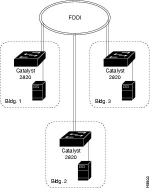
Catalyst 2800 Connected to a Trunk Ring via FDDI Fiber DAS
shows multiple Catalyst 2800s connected to a trunk ring. Each Catalyst 2800 is configured with an FDDI Fiber DAS module and a 100BaseTX/1 module for a local server connection.
Figure 3-1 Catalyst 2800 Connected to a Trunk Ring via FDDI Fiber DAS
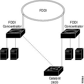
Catalyst 2800 Connected to a Concentrator in a Dual-Homing Configuration via FDDI Fiber DAS
shows a Catalyst 2800 connected to a concentrator in a dual-homing configuration using a Fiber DAS module.
Figure 3-2 Catalyst 2800 Connected to a Concentrator in a Dual Homing Configuration via FDDI Fiber DAS
Catalyst 2800 Connected to a Concentrator via FDDI Fiber SAS
shows multiple Catalyst 2800s connected to a concentrator. Each Catalyst 2800 is configured with an FDDI Fiber SAS module and a 100BaseTX/1 module for a local server connection. This configuration also applies to a Catalyst 2800 connected to a server or router port.
Figure 3-3 Catalyst 2800 Connected to a Concentrator via FDDI Fiber SAS
Catalyst 2800 Connected to a Server or Router via FDDI UTP SAS
shows a Catalyst 2800 connected to a server using a UTP SAS module. This configuration also applies to a Catalyst 2800 connected to a concentrator or router port.
Figure 3-4 Catalyst 2800 Connected to a Server or Router via FDDI UTP SAS
100Base-T Cabling Guidelines
This section describes 100Base-T cabling guidelines and some common configurations for Catalyst 2800 modules. The following cabling guidelines apply to a 100Base-T network:
•
•
•
•
To determine your cable budget, use the following formula:
400 - (R x 95) = Maximum cable length between any two nodes (in meters)
R represents the number of 100Base-T repeaters.
lists the maximum cable length between two nodes in a 100Base-T network.
Table 3-2 Cabling Limits in a 100Base-T Network
Note
100Base-T Cabling Example
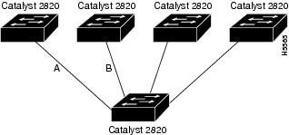
The maximum cable length between any two nodes in a one repeater 100Base-T network is 305 meters. illustrates this guideline. A Catalyst 2800 with a 100BaseFX/4 repeater module installed is connected to four other Catalyst 2800s via fiber. In this example, the total length of cable A plus cable B must be 305 meters or less.
Figure 3-5 100Base-T One Repeater Network
Common Catalyst 2800 Fast Ethernet Configurations
This section describes several common Catalyst 2800 network configurations:
•
•
•
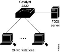
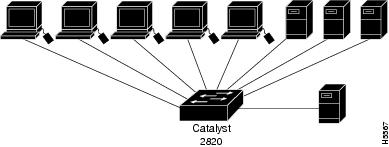
Catalyst 2800 Connected to a High Performance Client-Server Workgroup
shows a Catalyst 2800 connected to a high-performance client-server workgroup using the following:
•
•
The servers and workstations are configured with 100Base-T adapters.
Figure 3-6 High-Performance Client-Server Workgroup
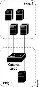
Catalyst 2800 Connected to Servers via Fiber
shows a Catalyst 2800 connected to several 100Base-T servers via fiber using the following:
•
•
The servers in building 2 in this example are configured with fiber 100Base-T adapters.
Figure 3-7 Catalyst 2800 Connected to Servers via Fiber
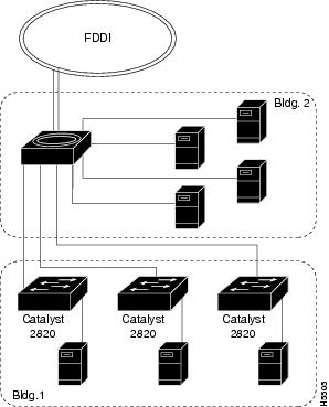
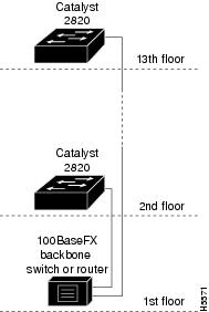
Catalyst 2800 Connected to a Fiber Fast Ethernet Backbone
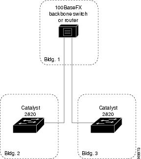
shows multiple Catalyst 2800s connected via fiber in a high-rise building network environment using the following:
•
•
Figure 3-8 Catalyst 2800s Connected via Fiber in a High-Rise Building
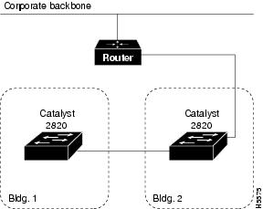
shows multiple Catalyst 2800s connected via fiber in a campus network environment using the following:
•
•
Figure 3-9 Catalyst 2800s Connected via Fiber in a Campus Environment
shows two Catalyst 2800s with the CollisionFree option connected via fiber using two Catalyst 2800s with 100BaseFX/1 modules installed.
With fiber and full duplex operation, the cable distance between two Catalyst 2800s extends to two kilometers.
Figure 3-10 Two Catalyst 2800s Connected via a Fiber Full Duplex Link