Feedback
Table Of Contents
Group Status LEDs (Shared Fast Ethernet Ports Only)
Introduction
Designed for use with the Catalyst 2800 high-speed expansion slots, the Catalyst 2800 modules consist of three FDDI modules that support both fiber optic and Category 5 UTP cabling, and four 100Base-T modules that can support the 100Base-TX and 100Base-FX physical media specifications.
These hot-pluggable modules are installed without interrupting the network and plug directly into the Catalyst 2800's high-speed expansion slot without the use of tools. The Catalyst 2800 then automatically diagnoses and configures the module to the network and verifies its operation.
Key Features
•
High-speed data rates: 100 megabits per second for 100Base-T; 100,000 packets per second for FDDI.
•
•
•
•
•
•
•
Packing List
•
•
•
FDDI Modules
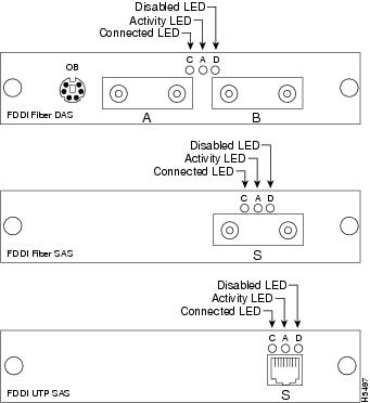
FDDI front panels, shown in , contain all of the network connectors and LEDs.
Figure 1-1 FDDI Modules
Fiber DAS Module
The FDDI Fiber DAS module is a dual-attach station (DAS) and is compatible with the ANSI X3T12 standard. It has two MIC connectors and uses 50/125 or 62.5/125 micron multimode fiber optic cabling. It also has a six-pin mini-DIN connector to connect to an optical bypass switch.
Fiber SAS Module
The FDDI Fiber SAS is a single-attach station (SAS) and is compatible with the ANSI X3T12 standard. It has one MIC connector and uses 50/125 or 62.5/125 micron multimode fiber optic cabling.
UTP SAS Module
The FDDI UTP SAS module is a single-attach station (SAS) compatible with the ANSI X3T12 standard. It has an RJ-45 connector and uses two-pair Category 5 UTP cabling.
FDDI Module LEDs
The following three LEDs on the front panel indicate a module's operating status:
•
When on, this LED indicates that the module is connected to an operational FDDI ring. When off, it indicates that the device is not connected to the FDDI ring.
•
This LED blinks when the corresponding port is transmitting or receiving data. It blinks rapidly when the traffic level is high; it is off when there is no activity.
•
This LED is on when the port has been disabled by administrative intervention or by a secure address violation. You can disable a port with Catalyst 2800's out-of-band Management Console.
The LEDs also indicate the type of failure when the module does not pass the Power-On Self-Test (POST). See in the "" chapter for more information.
Fast Ethernet Modules
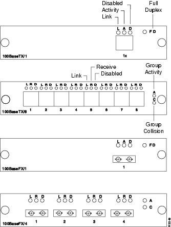
All network connectors and LEDs are on the module's front panel. The Fast Ethernet module front panels are shown in .
Figure 1-2 Fast Ethernet Module Front Panels
Fast Ethernet Ports
The Fast Ethernet modules are available in 100Base-TX and 100Base-FX configurations, supporting both switched and shared 100 Mbps operation.
The single switched Fast Ethernet ports provide a dedicated 100 Mbps of bandwidth for direct connection to a single server, workstation, or another Catalyst 2800. The shared Fast Ethernet ports connect to the same types of devices as the switched Fast Ethernet ports, but share 100 Mbps of bandwidth across all the ports.
100Base-TX Modules
The 100Base-TX modules are compatible with the 100Base-TX draft standard. They have RJ-45 connectors and use two-pair Category 5 UTP cabling. The following port configurations are available:
•
•
100Base-FX Modules
The 100Base-FX modules are compatible with the 100Base-FX draft standard. They have ST connectors and use 50/125 or 62.5/125 micron multimode fiber optic cabling. The following port configuration are available:
•
•
Fast Ethernet Module LEDs
The Fast Ethernet modules have individual Port and Group Status LEDs and a Full Duplex LED. These LEDs are shown in and are described in the following sections.
•
Three status LEDs are included for each individual Fast Ethernet port: Link Integrity, Network Activity or Receive, and Disabled.
•
The Link LED indicates that the port is properly connected to a powered-on device. this LED is on when the link integrity test passes and off when the link integrity test fails.
Note
•
The Activity LED for switched Fast Ethernet ports blinks when the corresponding port is transmitting or receiving data. If the traffic level is high, this LED will be on continuously. This LED is off when there is no activity.
•
The Receive LED for shared Fast Ethernet ports blinks whenever the corresponding port is receiving data. If the traffic level is high, this LED will be on continuously. This LED is off when there is no activity.
•
The Disable LED is on when the port is disabled or suspended, either by a network connection error or secure address violation, or manually disabled or suspended using the Catalyst 2800 in-band or out-of-band management system. If a shared Fast Ethernet port is automatically disabled due to a jabber or autopartition error, this LED blinks on.
•
The Full Duplex LED indicates when a switched Fast Ethernet port has been set to operate in full duplex mode. This LED is on when the port is operating in full duplex mode and off when the port is operating in half duplex mode.
Group Status LEDs (Shared Fast Ethernet Ports Only)
Two Group Status LEDs are included for the shared Fast Ethernet modules:
•
The Group Activity LED blinks when the corresponding shared Fast Ethernet ports are transmitting or receiving data. If the traffic level is high, this LED will be on continuously. This LED is off when there is no activity.
•
The Group Collision LED blinks when the corresponding shared Fast Ethernet ports detect a packet collision. This LED is off when there are no packet collisions detected.