Feedback
Table Of Contents
Power-On Self-Test (POST) for FDDI
POST for Fast Ethernet Modules
Installation
This chapter describes how to install the Catalyst 2800 modules in the Catalyst 2800 high-speed expansion slots. When unpacking the Catalyst 2800 modules, check the contents of the package against the list in "Packing List" in the "" chapter.
Note
All of the Catalyst 2800 modules are hot-pluggable: you can install a module without turning off the Catalyst 2800.
Removing a Blank Face Plate
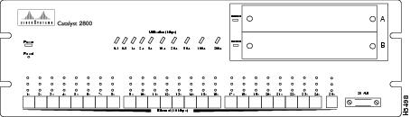
Blank face plates cover the high-speed expansion slots on the Catalyst 2800. shows a Catalyst 2800 with two blank face plates.
To remove the face plates, do the following:
Step 1
Step 2
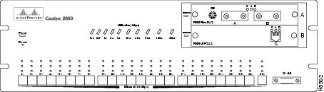
Figure 2-1 Catalyst 2800 with Blank Face Plates
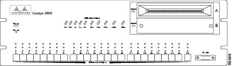
Figure 2-2 Catalyst 2800 with an Empty High-Speed Expansion Slot
Installing a Module
After the face plate has been removed, follow these steps to install a module into an empty Catalyst 2800 high-speed expansion slot:
Step 1
Step 2
When the module is installed correctly, its face plate sits flush against the front of the Catalyst 2800 unit.
Step 3
If you are attaching a fiber cable, remove the rubber plugs from the fiber port on the module and store the plugs for future use.
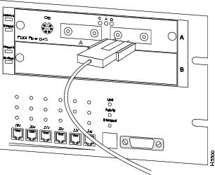
a For an MIC Connector, attach the cable, remove the protecting cap from the cable, line up the key slot on the cab header with the raised key in the fiber MIC connector. Insert the cable, as shown in , into the fiber port until the locks snap into place.Figure 2-3 Attaching a Fiber Optic Cable to an FDDI Module
CautionWhen installing a fiber module, do not remove the rubber plugs from the fiber port or the rubber caps from the fiber cable until you are ready to connect the cable. The plugs and caps protect the fiber port and cable from contamination and ambient light.
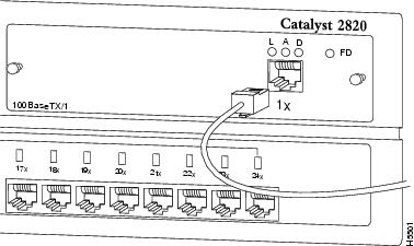
b For an ST connector, line up the two small tabs on the cable header with the keyed holes in the fiber connector. Insert the cable into the fiber port, turn clockwise one-quarter turn, and release the cable.c If you are attaching a UTP cable, insert the cable into the RJ-45 connector on the module as illustrated in .Figure 2-4 Attaching a UTP Cable to the FDDI Module
The module is now installed. The Catalyst 2800 should look like .
Note
Removing a Module
Figure 2-5 Installed FDDI Module
shows a Catalyst 2800 with two FDDI modules installed. To remove a module from a Catalyst 2800 high-speed expansion slot, do the following:
Step 1
a If you are removing a UTP cable, disconnect it from the RJ-45 connector.b If you are removing a MIC connector, press in the locks on the cable header and then pull the cable from the port. Replace the protective cap on the end of the fiber cable and the rubber plugs in the fiber port.c If you are removing an ST connector, grasp the circular part of the cable header, push it in slightly while turning it counter-clockwise, then pull the cable from the port.Step 2
Step 3
Power-On Self-Test (POST) for FDDI
When an FDDI module is installed in a Catalyst 2800, all LEDs on the module front panel are on, and the module automatically begins its Power-On Self-Test or POST. If the module passes the POST, the module enabled LED on the Catalyst 2800 remains on. If the module fails the Post, the module enabled LED blinks. For more information about the module enabled LED, refer to the Catalyst 2800 User Guide.
If the module fails the POST, the LEDs on the module indicate the type of failure. shows how to read LEDs for possible POST failures.
Table 2-1 LED Indicators of Failed FDDI POST
POST for Fast Ethernet Modules
When first powered on, all LEDs on the module front panel are on, and a Power-On Self-Test (POST) automatically begins. If the module passes POST, the Module Enabled LED on the Catalyst 2800 remains on. If the module fails POST, the Module Enabled LED is off to indicate a problem.
For a complete description of each LED, see "Fast Ethernet Module LEDs" in the chapter "."