Feedback
Table Of Contents
Optical Bypass Switch Connector Pinout
Connector Pinouts
This appendix describes the connectors for the following types of Catalyst 2800 modules:
•
FDDI modules
•
FDDI Modules
This section describes the following:
•
•
•
UTP SAS Connector Pinouts
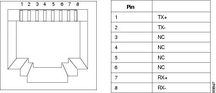
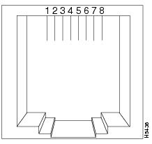
The UTP SAS module uses standard RJ-45 connectors. The arrangement of the pins is shown in . Note that connector shells are attached to chassis ground. Stations are always attached with a cross-over cable.
Figure B-1
RJ-45 Connector
FDDI Fiber Connector Pinouts
The FDDI module uses standard MIC connectors, as shown in .
Figure B-2 FastMate FDDI MIC Connectors
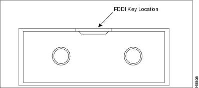
The receptacle keys for ports A and B of the FastMate Fiber DAS module are shown in a simplified form in .
Figure B-3 Receptacle Keys for Ports A and B
Optical Bypass Switch Connector Pinout
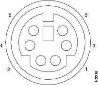
The Fiber DAS module uses a 6-pin mini-DIN connector for the optical bypass switch. The pin arrangement is shown in .
Figure B-4 Six-Pin Mini-DIN Connector
Fast Ethernet Pinouts
This section describes the two connectors for the Catalyst 2800 Fast Ethernet modules:
•
•
100Base-TX Connector Pinouts
The 100Base-TX modules use standard RJ-45 connectors. The arrangement of the pins is shown in , and the pinouts are shown in .
Figure B-5 100Base-TX Connector
Table B-1 100Base-TX Connector
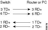
Connector shells are attached to chassis ground. The 100Base-TX ports have their transmit (TD) and receive (RD) pairs internally crossed (designated by the x) for attachment to an adapter using a straight-through cable.
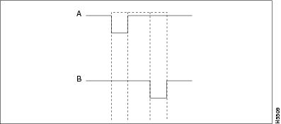
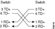
The straight-through and crossover cable schematics are shown in and .
Figure B-6 Straight-through Cable Schematic
Figure B-7 Crossover Cable Schematic
100Base-FX Connector Pinouts
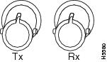
The 100Base-FX modules use standard ST connectors. The arrangement of the pins is shown in .
Figure B-8 100Base-FX Connector