Feedback
Table Of Contents
FC-Redirect Unsupported Switches
Configuring FC-Redirect v2 Mode
Using FC-Redirect with CFS Regions
Guidelines for Designing CFS Regions For FC-Redirect
Configuring CFS Regions For FC-Redirect
Using IOA Cluster with IPFC Interface
Task Flow for Configuring IOA Cluster To Use the IPFC Interface
Configuring IOA Cluster To Use the IPFC Interface
Creating a VSAN Interface and Configuring IPv4 Addresses
Creating IOA cluster and IOA interface in the Local Node
Verifying Cluster Configuration
Adding a Remote Node and IOA Interface to the Remote Node
Verifying the Cluster Configuration
Configuring IOA Site on Switch sw-231-14
Configuring IOA Site on Switch sw-231-19
Configuring IOA Cluster cltr1 on Switch sw-231-14
Changing the Node to Use IPFC Interface Address
Adding a Remote Node to the IOA Cluster
Adding an IOA Interface to the Switch sw-231-14
Adding an IOA Interface to the Switch sw-231-19
Verifying the Cluster Configuration
Task Flow for Converting an Existing IOA Cluster to use IPFC interface
Configuration Example for Converting IOA Cluster to Use the IPFC interface
Verifying the IOA Cluster Configuration
Shutting Down IOA Cluster on a Local Node
Shutting Down the IOA cluster on the remote node
Removing the IOA Cluster from the Remote Node
Verifying the IOA Cluster in the Remote Node
Removing the Remote Node from the Cluster in the Local Switch
Changing the Local Node Configuration to use IPFC Address
Activating the Single Node Cluster
Adding Remote Node with IPFC Address
Adding IOA Interfaces to the Remote Node
Getting Started
This chapter provides an overview of the basic configurations that need to be completed before getting started with IOA-specific configurations:
•
Configuring FC-Redirect v2 Mode
•
•
Enabling SSH
SSH needs to be enabled on all the IOA switches for Fabric Manager to provision IOA. By default, the SSH service is enabled with the RSA key.
To enable the SSH service, follow these steps:
Step 1
switch# config t
Enters configuration mode.
Step 2
switch(config)# feature ssh
updated
Enables the use of the SSH service.
For more information about the SSH service, refer to the Cisco MDS 9000 Family NX-OS Security Configuration Guide.
Enabling CFS
CFS must be enabled on the IOA switches as well as those switches of which the hosts and targets are directly connected to. FC-Redirect internally uses CFS to configure the rules for any given flow in the fabric.
To globally enable CFS distribution on a switch, follow these steps:
Step 1
switch# config t
switch(config)#
Enters configuration mode.
Step 2
switch(config)# cfs distribute
Enables (default) CFS distribution on the switch.
For more information about CFS, refer to the Cisco MDS 9000 Family NX-OS System Management Configuration Guide.
IP Access Lists
Cluster communication requires the use of the Management interface. IP ACL configurations must allow UDP and TCP traffic on ports 9333, 9334, 9335, and 9336.
Zone Default Policy
For FC-Redirect to work correctly, the default zone policy on all the switches in the IOA environment must be configured to deny and the initiator-target pairs must be configured in user-defined zones.
FC-Redirect
This section includes the following topics:
•
FC-Redirect Unsupported Switches
FC-Redirect is not supported on the following switches, which also means that IOA is not supported:
•
•
•
•
•
•
FC-Redirect Requirements
FC-Redirect requirements for IOA include the following:
•
•
•
•
•
•
Configuring FC-Redirect v2 Mode
To enable the v2 mode in FC-Redirect, use the fc-redirect version2 enable command in configuration mode. To disable the v2 mode in FC-Redirect, use the no form of the command.
This command is used to increase scalability of FC-Redirect. Disabling v2 mode after it is enabled in the fabric is not recommended. However, if you want to disable v2 mode, you cannot disable it until all FC-Redirect configurations are deleted. FC-Redirect configurations can be deleted only by deleting all corresponding application configurations.
The MDS switches not running Cisco NX-OS 3.3(1c) and later cannot be added to the fabric after the v2 mode is enabled. If the switches are added, all further FC-Redirect configuration changes will fail across the fabric. This could lead to traffic disruption for applications such as IOA, SME, and DMM.
Use the show fc-redirect configs command to see the list of applications that create FC-Redirect configurations.
If v2 mode is enabled in the fabric and you want to move a switch to a different fabric, use the clear fc-redirect decommission-switch command before moving the switch to a different fabric. If the mode is not enabled, all switches in the new fabric will be converted to v2 mode automatically.
Note
To enable v2 mode in FC-Redirect, follow these steps:
Step 1
switch# fc-redirect version2 enableStep 2
Please make sure to read and understand the following implicationsbefore proceeding further:1) This is a Fabric wide configuration. All the switches in thefabric will be configured in Version2 mode.Any new switchesadded to the fabric will automatically be configured in version2mode.2) SanOS 3.2.x switches CANNOT be added to the Fabric after Version2mode is enabled. If any 3.2.x switch is added when Version2 modeis enabled, all further FC-Redirect Configuration changes will Failacross the fabric. This could lead to traffic disruption forapplications like SME.3) If enabled, Version2 mode CANNOT be disabled till all FC-Redirectconfigurations are deleted. FC-Redirect configurations can bedeleted ONLY after all the relevant application configurationsare deleted. Please use the command 'show fc-redirect configs'to see the list of applications that created FC-Redirectconfigurations.4) 'write erase' will NOT disable this command. After 'write erase'on ANY switch in the fabric, the user needs to do:'clear fc-redirect decommission-switch'on that that switch. Without that, if the user moves the switchto a different fabric it will try to convert all the switchesin the fabric to Version2 mode automatically. This might leadto Error conditions and hence Traffic disruption.Do you want to continue? (Yes/No) [No]YesStep 3
Before proceeding further, please check the following:1) All the switches in the fabric are seen in the output of'show fc-redirect peer-switches' command and are in 'UP' state.2) All switches in the fabric are running SanOS version 3.3.x orhigher.3) Please make sure the Fabric is stable ie.,No fabric changes/upgrades in progressDo you want to continue? (Yes/No) [No] Yes
Using FC-Redirect with CFS Regions
The FC-Redirect feature uses Cisco Fabric Services (CFS) regions to distribute the FC-Redirect configuration. By default, the configuration is propagated to all FC-Redirect-capable switches in the fabric. CFS regions can be used to restrict the distribution of the FC-Redirect configuration.
Note
To learn more about CFS regions, refer to the Cisco MDS 9000 Family NX-OS System Management Configuration Guide.
Guidelines for Designing CFS Regions For FC-Redirect
To design CFS regions for FC-Redirect, follow these guidelines:
•
•
•
•
•
Configuring CFS Regions For FC-Redirect
To configure the CFS regions for FC-Redirect, do the following tasks:
Step 1
switch# config tswitch# cfs region 2switch# fc-redirectswitch# endRepeat this step for all the switches that are included in the specified region.
Step 2
Step 3
a.
b.
Using IOA Cluster with IPFC Interface
Internet protocol over Fibre Channel (IPFC) provides IP forwarding or in-band switch management over a Fibre Channel interface (instead of management using the Gigabit Ethernet mgmt 0 interface). You can use IPFC to specify that IP frames be transported over Fibre Channel using encapsulation techniques. IP frames are encapsulated into Fibre Channel frames so that cluster management information can transmit across the Fibre Channel network without using an overlay Ethernet network.
When you use IOA cluster with the IPFC interface, the IOA cluster can use cluster management-related messages through Fibre Channel ISLs by encapsulating cluster management related messages in to Fibre Channel frames instead of using the management interface.
Note
Note
Task Flow for Configuring IOA Cluster To Use the IPFC Interface
To configure IOA cluster using the IPFC Interface, follow these steps:
Step 1
a.
b.
c.
d.
Step 2
Step 3
Step 4
Step 5
Step 6
Configuring IOA Cluster To Use the IPFC Interface
The process of configuring an IOA cluster to use the IPFC interface involves a number of configuration tasks that should be completed in the following order:
•
•
•
•
•
Creating a VSAN Interface and Configuring IPv4 Addresses
The first step in the process of configuring IOA cluster to use the IPFC interface is to create a VSAN interface and configure IPv4 addresses.
To create an interface VSAN, perform this task:
After creating the VSAN and configuring the IPv4 address, use the show interface vsan command to verify the configuration:
sw-231-14# show interface vsan 1vsan1 is up, line protocol is upWWPN is 10:00:00:0d:ec:18:a1:05, FCID is 0xec03c0Internet address is 10.1.1.1/24MTU 1500 bytes, BW 1000000 Kbit0 packets input, 0 bytes, 0 errors, 0 multicast6 packets output, 384 bytes, 0 errors, 0 droppedsw-231-14#Enabling IPv4 Routing
To enable IPv4 routing, perform this task:
Step 1
Switch# config t
Enters configuration mode.
Step 2
Switch(config)# ip routing
Enables IPV4 routing.
Step 3
Switch(config) no ip routing
Disables IPV4 routing.
After enabling IPv4 routing, use the show ip routing to verify the configuration.
sw-231-14(config)# show ip routingip routing is enabledVerifying Connectivity
To verify the connectivity, use the show ip route and ping commands.
sw-231-14# show ip routeCodes: C - connected, S - staticC 10.1.1.0/24 is directly connected, vsan1sw-231-14# ping 10.1.1.2PING 10.1.1.2 (10.1.1.2) 56(84) bytes of data.64 bytes from 10.1.1.2: icmp_seq=1 ttl=64 time=0.875 ms64 bytes from 10.1.1.2: icmp_seq=2 ttl=64 time=0.866 ms64 bytes from 10.1.1.2: icmp_seq=3 ttl=64 time=0.884 ms64 bytes from 10.1.1.2: icmp_seq=4 ttl=64 time=0.875 ms--- 10.1.1.2 ping statistics ---4 packets transmitted, 4 received, 0% packet loss, time 3023msrtt min/avg/max/mdev = 0.866/0.875/0.884/0.006 msCreating IOA cluster and IOA interface in the Local Node
To create an IOA cluster and IOA interface in the local node, perform this task:
To configure an IOA cluster, you can use the name of the switch if the network supports DNS service. The IOA cluster requires switch name to IP address resolution.
Verifying Cluster Configuration
To verify the cluster configuration, use the show ioa cluster name node summary command.
sw-231-14# sh ioa cluster cltr1 node sum-------------------------------------------------------------------------------Switch Site Status Master Node ID-------------------------------------------------------------------------------sw-231-14(L) site2 online yes 1To verify the IP address of the node, use the show ioa cluster <name> node command.
sw-231-14# show ioa cluster cltr1 nodeNode sw-231-14 is local switchNode ID is 1IP address is 10.1.1.1Status is onlineBelongs to Site site2Node is the master switchAdding a Remote Node and IOA Interface to the Remote Node
To add a remote node, perform this task:
Verifying the Cluster Configuration
To verify the node configuration, use the show ioa cluster name node summary command:
sw-231-14# show ioa cluster cltr1 node summary-------------------------------------------------------------------------------Switch Site Status Master Node ID-------------------------------------------------------------------------------sw-231-14(L) site2 online yes 1sw-231-19 site1 online no 2To verify the ip address of the node, use the show ioa cluster name node command:
Node sw-231-14 is local switchNode ID is 1IP address is 10.1.1.1Status is onlineBelongs to Site site2Node is the master switchNode sw-231-19 is remote switchNode ID is 2IP address is 10.1.1.2Status is onlineBelongs to Site site1Node is not master switchsw-231-14#To see all of the configured interfaces in the IOA cluster, use the show ioa cluster name interface summary command:
sw-231-14# show ioa cluster cltr1 interface summary-------------------------------------------------------------------------------Switch Interface Status Flows-------------------------------------------------------------------------------sw-231-14(L) ioa1/1 up 0sw-231-14(L) ioa1/2 up 0sw-231-19 ioa4/1 up 0sw-231-19 ioa4/2 up 0sw-231-14#Configuration Example
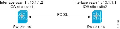
This section includes an example for creating an IOA cluster using IPFC interface. Figure 2-1 illustrates the IOA cluster configuration used in this example. The sample topology shows the FC ISL between sw-231-14 and sw-231-19 switches.
Figure 2-1
Configuration Example
•
•
•
•
•
•
•
Creating an Interface VSAN
The following example creates an interface VSAN and configure IP address on sw-231-14 and enable IP routing:
sw-231-14(config)# int vsan 1sw-231-14(config-if)# ip address 10.1.1.1 255.255.255.0sw-231-14(config-if)# no showsw-231-14(config)# ip routingsw-231-14(config)#The following example create an interface VSAN and configure IP address on sw-231-19 and enable IP routing.
sw-231-19(config)# int vsan 1sw-231-19(config-if)# ip address 10.1.1.12 255.255.255.0sw-231-19(config-if)# no showsw-231-19(config)# ip routingVerifying the Configuration
The following example verifies the configuration of sw-231-14 using show interface command.
sw-231-14# show interface vsan 1vsan1 is up, line protocol is upWWPN is 10:00:00:0d:ec:18:a1:05, FCID is 0xec03c0Internet address is 10.1.1.1/24MTU 1500 bytes, BW 1000000 Kbit758 packets input, 110841 bytes, 0 errors, 42 multicast651 packets output, 122577 bytes, 0 errors, 0 droppedsw-231-14#The following example verifies the configuration of sw-231-19 using show interface command:
sw-231-19# show interface vsan 1vsan1 is up, line protocol is upWWPN is 10:00:00:05:30:01:9f:09, FCID is 0xc60000Internet address is 10.1.1.2/24MTU 1500 bytes, BW 1000000 Kbit675 packets input, 124613 bytes, 0 errors, 36 multicast755 packets output, 111785 bytes, 0 errors, 0 droppedsw-231-19#Verifying the Connectivity
The following example verifies the connectivity using ping command:
sw-231-14# ping 10.1.1.2PING 10.1.1.2 (10.1.1.2) 56(84) bytes of data.64 bytes from 10.1.1.2: icmp_seq=1 ttl=64 time=0.868 ms64 bytes from 10.1.1.2: icmp_seq=2 ttl=64 time=0.898 ms64 bytes from 10.1.1.2: icmp_seq=3 ttl=64 time=0.906 ms--- 10.1.1.2 ping statistics ---3 packets transmitted, 3 received, 0% packet loss, time 2017msrtt min/avg/max/mdev = 0.868/0.890/0.906/0.038 mssw-231-14#Configuring IOA Site on Switch sw-231-14
The following example configures IOA site on switch sw-231-14:
sw-231-14(config)# ioa site-local site2sw-231-14(config)#Configuring IOA Site on Switch sw-231-19
The following example configures IOA site on switch sw-231-19:
sw-231-19(config)# ioa site-local site1sw-231-19(config)#Configuring IOA Cluster cltr1 on Switch sw-231-14
The following example configures IOA cluster ctrl1 on switch sw-231-14:
sw-231-14(config)# ioa cluster cltr12011 Apr 8 05:00:46 sw-231-14 %CLUSTER-2-CLUSTER_LEADER_ANNOUNCE: Node 0x1 is the new Master of cluster 0x2e05000dec18a133 of 1 nodes2011 Apr 8 05:00:46 sw-231-14 %CLUSTER-2-CLUSTER_QUORUM_GAIN: Cluster 0x2e05000dec18a133 now has quorum with 1 nodesChanging the Node to Use IPFC Interface Address
The following example force the node to use IPFC interface addresss:
sw-231-14(config-ioa-cl)# node sw-231-14 ip-address 10.1.1.1sw-231-14(config-ioa-cl-node)# exAdding a Remote Node to the IOA Cluster
The following example adds a remote node to IOA cluster:
sw-231-14(config-ioa-cl)# node sw-231-19 ip-address 10.1.1.22011 Apr 8 05:02:47 sw-231-14 %CLUSTER-2-CLUSTER_QUORUM_GAIN: Cluster 0x2e05000dec18a133 now has quorum with 1 nodes2011 Apr 8 05:02:52 sw-231-14 %CLUSTER-2-CLUSTER_QUORUM_GAIN: Cluster 0x2e05000dec18a133 now has quorum with 2 nodessw-231-14(config-ioa-cl-node)# exAdding an IOA Interface to the Switch sw-231-14
The following example adds an IOA interface on the switch sw-231-14:
sw-231-14(config-ioa-cl)# node sw-231-14sw-231-14(config-ioa-cl-node)# int ioa 1/1sw-231-14(config-ioa-cl-node)# int ioa 1/2sw-231-14(config-ioa-cl-node)# exAdding an IOA Interface to the Switch sw-231-19
The following example adds an IOA interface on the switch sw-231-19:
sw-231-14(config-ioa-cl)# node sw-231-19sw-231-14(config-ioa-cl-node)# int ioa 4/1sw-231-14(config-ioa-cl-node)# int ioa 4/2sw-231-14(config-ioa-cl-node)# exVerifying the Cluster Configuration
The following example verifies the cluster configuration using show cluster name node summary command:
sw-231-14# show ioa cluster cltr1 node summary-------------------------------------------------------------------------------Switch Site Status Master Node ID-------------------------------------------------------------------------------sw-231-14(L) site2 online yes 1sw-231-19 site1 online no 2Verifying the IP Address
The following example verifies the IP Address that is configured on the switch using show ioa cluster cluster name node command:
sw-231-14# show ioa cluster cltr1 nodeNode sw-231-14 is local switchNode ID is 1IP address is 10.1.1.1Status is onlineBelongs to Site site2Node is the master switchNode sw-231-19 is remote switchNode ID is 2IP address is 10.1.1.2Status is onlineBelongs to Site site1Node is not master switchVerifying the IOA Interface
The following example verifies the IOA interface that is configured on the switch using show ioa cluster cluster name interface summary command:
sw-231-14# show ioa cluster cltr1 int summary-------------------------------------------------------------------------------Switch Interface Status Flows-------------------------------------------------------------------------------sw-231-14(L) ioa1/1 up 0sw-231-14(L) ioa1/2 up 0sw-231-19 ioa4/1 up 0sw-231-19 ioa4/2 up 0sw-231-14#Task Flow for Converting an Existing IOA Cluster to use IPFC interface
To convert an existing IOA cluster to use the IPFC Interface, follow these steps:
•
•
•
•
•
•
•
Configuration Example for Converting IOA Cluster to Use the IPFC interface
This example for converting an IOA cluster to use the IPFC interface has the following steps:
•
•
•
•
•
•
•
•
•
•
Verifying the IOA Cluster Configuration
The following example verifies the IOA cluster configuration that is configured on the switch using show ioa cluster cluster name node summary command:
sw-231-14(config)# show ioa cluster cltnew node summary-------------------------------------------------------------------------------Switch Site Status Master Node ID-------------------------------------------------------------------------------sw-231-14(L) site2 online yes 1sw-231-19 site1 online no 2Verifying the IP Address
The following example verifies the IP address that is configured on the switch using the show ioa cluster cluster name node command:
sw-231-14(config)# show ioa cluster cltnew nodeNode sw-231-14 is local switchNode ID is 1IP address is 172.25.231.14Status is onlineBelongs to Site site2Node is the master switchNode sw-231-19 is remote switchNode ID is 2IP address is 172.25.231.19Status is onlineBelongs to Site site1Node is not master switchVerifying the Flow Status
The following example verifies the status of the flows using the show ioa cluster cluster name flows command. The nodes in this example are using mgmt0 interface address
sw-231-14(config)# show ioa cluster cltnew flows-------------------------------------------------------------------------------Host WWN, VSAN WA TA Comp Status Switch,InterfaceTarget WWN Pair-------------------------------------------------------------------------------21:01:00:1b:32:22:55:df, 1 Y Y N online sw-231-14, ioa1/121:01:00:0d:77:dd:f8:9d, 1 sw-231-19, ioa4/1Shutting Down IOA Cluster on a Local Node
The following example shuts down the IOA cluster on a local node using shut down command.
sw-231-14(config)# ioa cluster cltnewsw-231-14(config-ioa-cl)# showThis change can be disruptive. Please ensure you have read the "IOA Cluster Recovery Procedure" in the configuration guide. -- Are you sure you want to continue? (y/n) [n] y2011 Apr 8 05:36:41 sw-231-14 %CLUSTER-2-CLUSTER_LOCAL_NODE_EXIT: Local Node 0x1 has left the Cluster 0x2e06000dec18a133Shutting Down the IOA cluster on the remote node
The following example shuts down the IOA cluster on the remote node using shut down command:
sw-231-19(config)# ioa cluster cltnewsw-231-19(config-ioa-cl)# showThis change can be disruptive. Please ensure you have read the "IOA Cluster Recovery Procedure" in the configuration guide. -- Are you sure you want to continue? (y/n) [n] y2011 Apr 8 05:37:03 sw-231-19 %CLUSTER-2-CLUSTER_LOCAL_NODE_EXIT: Local Node 0x2 has left the Cluster 0x2e06000dec18a133sw-231-19(config-ioa-cl)# exitRemoving the IOA Cluster from the Remote Node
The following example remove the IOA cluster from the remote node using the no ioa cluster cluster name command:
sw-231-19(config)# no ioa cluster cltnewVerifying the IOA Cluster in the Remote Node
The following example verify the presence of IOA cluster on the remote node using show ioa cluster cluster name command:
sw-231-19(config)# show ioa clustersw-231-19(config)#Removing the Remote Node from the Cluster in the Local Switch
The following example removes the remote node from the cluster in the local switch:
sw-231-14(config-ioa-cl)# no node sw-231-19sw-231-14(config-ioa-cl)# show ioa cluster cltnew node summary-------------------------------------------------------------------------------Switch Site Status Master Node ID-------------------------------------------------------------------------------sw-231-14(L) -- unknown (cluster is offline) 1Changing the Local Node Configuration to use IPFC Address
The following example change the local node to use IPFC address:
sw-231-14(config-ioa-cl)# node id 1 sw-231-14 ip-address 10.1.1.1sw-231-14(config-ioa-cl-node)# exitActivating the Single Node Cluster
The following example activates the single node cluster:
sw-231-14(config-ioa-cl)# no showThis change can be disruptive. Please ensure you have read the "IOA Cluster Recovery Procedure" in the configuration guide. -- Are you sure you want to continue? (y/n) [n] ysw-231-14(config-ioa-cl)# 2011 Apr 8 05:39:17 sw-231-14 %CLUSTER-2-CLUSTER_LEADER_ANNOUNCE: Node 0x1 is the new Master of cluster 0x2e06000dec18a133 of 1 nodes2011 Apr 8 05:39:17 sw-231-14 %CLUSTER-2-CLUSTER_QUORUM_GAIN: Cluster 0x2e06000dec18a133 now has quorum with 1 nodesAdding Remote Node with IPFC Address
The following example adds a remote node with IPFC address:
sw-231-14(config-ioa-cl)# node sw-231-19 ip-address 10.1.1.22011 Apr 8 05:39:36 sw-231-14 %CLUSTER-2-CLUSTER_QUORUM_GAIN: Cluster 0x2e06000dec18a133 now has quorum with 1 nodes2011 Apr 8 05:39:41 sw-231-14 %CLUSTER-2-CLUSTER_QUORUM_GAIN: Cluster 0x2e06000dec18a133 now has quorum with 2 nodesAdding IOA Interfaces to the Remote Node
The following example adds the IOA interfaces to the remote node:
sw-231-14(config-ioa-cl-node)# int ioa 4/1sw-231-14(config-ioa-cl-node)# endsw-231-14#Verifying the Cluster Nodes
The following example verifies the status of the IOA clusters using show ioa cluster cluster name node summary command:
sw-231-14# show ioa cluster cltnew node summary-------------------------------------------------------------------------------Switch Site Status Master Node ID-------------------------------------------------------------------------------sw-231-14(L) site2 online yes 1sw-231-19 site1 online no 2Verifying the Flow Status
The following example verifies the status of the IOA clusters using show ioa cluster cluster name flows command:
sw-231-14# show ioa cluster cltnew flows-------------------------------------------------------------------------------Host WWN, VSAN WA TA Comp Status Switch,InterfaceTarget WWN Pair-------------------------------------------------------------------------------21:01:00:1b:32:22:55:df, 1 Y Y N online sw-231-14, ioa1/121:01:00:0d:77:dd:f8:9d, 1 sw-231-19, ioa4/1sw-231-14#