Table Of Contents
Testing the CPwE Solution
Overview
Introduction
Test Objective
Test Equipment
Network Equipment
Network Topology
IACS Equipment
Test Approach
Network Resiliency
Application-Level Latency and Jitter (Screw-to-Screw)
Test Execution
Network Resiliency
Test Cases
Application-level Latency and Jitter
Test Results Summary
Testing the CPwE Solution
Overview
This chapter describes the test plans and environment used to validate the key concepts outlined in this solution. This chapter covers the following:
•
Key test objectives, activities and exit criteria to validate the solution
•
Describe the test environments in which the tests will be conducted
•
Summarize the test execution steps including test scenarios and test cases
For detailed test results refer to "Complete Test Data" and refer to "Test Result Analysis" for analysis of those results. The intention of providing this level of detail is to allow implementers of IACS networks to estimate the various characteristics of their own networks (e.g., network convergence) and to compare their own test results to determine whether improvements are possible following the guidelines outlined in this Design and Implementation Guide.
Introduction
Test Objective
The objective of the test was to provide input and background for the requirements and solution architecture. The test approach is designed to enable Cisco and Rockwell Automation to provide detailed design and implementation guidance for applying industrial Ethernet to production facilities. The test was also designed to produce results that customers and implementers of IACS networks can use to plan and design their own networks. This test plan is designed to test key network characteristics to best support automation and control system. The key plant network design requirements and considerations to be tested include the following:
•
Performance/real-time communications (network latency and jitter)
•
Availability (e.g., resiliency protocols)
•
Adaptability (e.g., topology)
•
Security (e.g., remote access)
•
Scalability
The testing for the CPwE solution does not cover the following:
•
Automation and Control applications and the IACS devices themselves
•
Any of the environmental characteristics (temperature, shock, etc.) conditions of the network infrastructure or automation and control devices
•
Performance and scalability testing of Manufacturing zone
•
Full performance capability of the industrial Ethernet switches. In most well designed IACS networks and by applying the concepts within, the IACS applications generally do not produce the volume of traffic that would come anywhere near the performance thresholds of modern managed network switching infrastructure.
Test Equipment
The test equipment used for the testing falls into two categories: network infrastructure and IACS equipment.
Network Equipment
Table 7-1 list the network equipment used in this solution testing.
Table 7-1 Testing Equipment
Product / Platform
|
Models
|
Software Release
|
Notes
|
IE3000
|
IE-3000-4TC-E, IE-3000-8TC-E
|
12.2.50-SE (ED)
|
Crypto image with Device Manager installed
|
Stratix 8000
|
1783-MS06T, 1783-MS10T
|
12.2(46)SE2 (ED)
|
LAN Base w/ Web Based Device Manager
|
Catalyst 3750
|
3750G-24PS
3750G-12S (12 SFP Ports)
|
12.2.46-SE - IP Services
|
Crypto image with Device Manager installed. Models
|
Catalyst 4500
|
45007R
|
12.2(31)SGA
|
Core switches
|
ASA 5520
|
ASA-552-K8
|
8.0.3
|
|
Cisco Network Assistant
|
-
|
3.1
|
|
Ixia
|
Ixia 400Tf
|
IxOS 5.10.350.33
IxExplorer 5.10.350 Build 33
|
Used to inject simulated traffic to the network and measure convergence times.
|
For media interconnecting switches, either Cat 5E copper cabling or multi-mode fiber cabling was used.
Network Topology
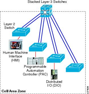
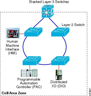
For the purposes of the testing, only the resilient network, and ring and redundant star topologies were used. In all cases, a distribution switch was part of the ring or redundant star topology. Figure 7-1 shows star topology and Figure 7-2 shows the ring topology tested for this solution.
Figure 7-1 Redundant Star Topology
Figure 7-2 Ring Topology
IACS Equipment
Table 7-2 IACS Equipment
Quantity
|
Catalog #
|
Description
|
|
|
L61 #3, CLGX_A, CLGX_B
|
1
|
1756-A7
|
1756 Chassis 7 slots
|
2
|
1756-EN2T
|
EtherNet 10-100M Bridge Module
|
2
|
1756-L64
|
Logix5564 Processor With 16 Mbytes Memory (PAC)
|
1
|
1756-PA75
|
85-265V AC Power Supply (5V @ 13 Amp)
|
|
|
|
L61 #3, CLGX_C, CLGX_D
|
1
|
1756-A7
|
1756 Chassis 7 slots
|
2
|
1756-EN2T
|
EtherNet 10-100M Bridge Module
|
2
|
1756-L64
|
Logix5564 Processor With 16 Mbytes Memory (PAC)
|
1
|
1756-PA75
|
85-265V AC Power Supply (5V @ 13 Amp)
|
|
|
|
L61 #2, CLGX_E, CLGX_F
|
1
|
1756-A10
|
1756 Chassis 10 slots
|
2
|
1756-EN2T
|
EtherNet 10-100M Bridge Module
|
1
|
1756-IB16ISOE
|
10-30 VDC Isolated Sequence of Event Input 16 Pts (36 Pin)
|
2
|
1756-L61
|
Logix5561 Processor With 2Mbytes Memory (PAC)
|
1
|
1756-OB16D
|
19-30 VDC Diagnostic Output 16 Pts (36 Pin)
|
1
|
1756-PA75
|
85-265V AC Power Supply (5V @ 13 Amp)
|
2
|
1756-TBCH
|
36 Pin Screw Clamp Block With Standard Housing
|
|
|
|
L61 #1, CLGX_G, CLGX_H
|
1
|
1756-A10
|
1756 Chassis 10 slots
|
2
|
1756-EN2T
|
EtherNet 10-100M Bridge Module
|
1
|
1756-ENBT
|
EtherNet 10-100M Bridge Module
|
1
|
1756-IB16
|
10-31 VDC Input 16 Pts (20 Pin)
|
2
|
1756-L61
|
Logix5561 Processor With 2Mbytes Memory (PAC)
|
1
|
1756-OB16E
|
10-31 VDC Elec Fused Output 16 Pts (20 Pin)
|
1
|
1756-PA75
|
85-265V AC Power Supply (5V @ 13 Amp)
|
2
|
1756-TBNH
|
20 Position NemA Screw Clamp Block
|
|
|
|
L43 #1 CPX_I
|
2
|
1768-ENBT
|
CompactLogix L4X Ethernet/IP Bridge Module
|
1
|
1768-L43
|
CompactLogix L45Processor, 3.0M Memory (PAC)
|
1
|
1768-PA3
|
CompactLogix 5V/24V ac Input Non-Redundant Power Supply for CompactLogix Systems
|
1
|
1769-ECR
|
Right End Cap Terminator
|
|
|
|
L32E #2 CPX_J
|
1
|
1769-ECR
|
Right End Cap Terminator
|
2
|
1769-IQ6XOW4
|
Combo 6pt 24 VDC Input, 4pt AC/DC Relay Output
|
1
|
1769-L32E
|
CompactLogix EtherNet Processor, 750k Memory (PAC)
|
1
|
1769-PA2
|
120/240V AC Power Supply (5V @ 2 Amp)
|
|
|
|
L43 #2 CPX_L
|
2
|
1768-ENBT
|
CompactLogix L4X Ethernet/IP Bridge Module
|
1
|
1768-L43
|
CompactLogix L45Processor, 3.0M Memory (PAC)
|
1
|
1768-PA3
|
CompactLogix 5V/24V ac Input Non-Redundant Power Supply for CompactLogix Systems
|
1
|
1769-ECR
|
Right End Cap Terminator
|
|
|
|
L32E #1 CPX_M
|
1
|
1769-ECR
|
Right End Cap Terminator
|
2
|
1769-IQ6XOW4
|
Combo 6pt 24 VDC Input, 4pt AC/DC Relay Output
|
1
|
1769-L32E
|
CompactLogix EtherNet Processor, 750k Memory (PAC)
|
1
|
1769-PA2
|
120/240V AC Power Supply (5V @ 2 Amp)
|
|
|
|
LS61S #1 CLGX_O
|
1
|
1756-A7
|
1756 Chassis 7 slots
|
2
|
1756-EN2T
|
EtherNet 10-100M Bridge Module
|
1
|
1756-L61S
|
Logix5561 Safety Processor With 2 Mbytes Memory (PAC)
|
1
|
1756-LSP
|
Safety Partner Coprocessor
|
1
|
1756-PA75
|
85-265V AC Power Supply (5V @ 13 Amp)
|
|
|
|
LS61S #2 CLGX_P
|
1
|
1756-A7
|
1756 Chassis 7 slots
|
2
|
1756-EN2T
|
EtherNet 10-100M Bridge Module
|
1
|
1756-L61S
|
Logix5561 Safety Processor With 2 Mbytes Memory (PAC)
|
1
|
1756-LSP
|
Safety Partner Coprocessor
|
1
|
1756-PA75
|
85-265V AC Power Supply (5V @ 13 Amp)
|
|
|
|
FlexIO #100
|
1
|
1794-AENT
|
Ethernet Adapter Module (Distributed I/O)
|
1
|
1794-IB8
|
24V DC Sink Input Module, 8 Point
|
1
|
1794-OB16
|
24V DC Source Output Module, 16 Point
|
1
|
1794-PS13
|
85-264 VAC To 24 VDC 1.3A Power Supply
|
2
|
1794-TB3
|
Terminal Base, 3-Wire
|
|
|
|
FlexIO 102
|
1
|
1794-AENT
|
Ethernet Adapter Module (Distributed I/O)
|
1
|
1794-IB8
|
24V DC Sink Input Module, 8 Point
|
1
|
1794-OB16
|
24V DC Source Output Module, 16 Point
|
1
|
1794-PS13
|
85-264 VAC To 24 VDC 1.3A Power Supply
|
2
|
1794-TB3
|
Terminal Base, 3-Wire
|
|
|
|
PointIO 103
|
1
|
1734-AENT
|
1734 EtherNet/IP Adapter (Distributed I/O)
|
1
|
1734-IB2
|
10-28 VDC 2 Points Sink Input Module
|
1
|
1734-IR2
|
2 Points RTD Input Module
|
1
|
1734-OW4
|
4 Points Relay Output Module
|
2
|
1734-TB
|
Two-Piece Terminal Base, 8-point, Screw Clamp Terminals
|
1
|
1734-TB3
|
Two-Piece Terminal Base, 12-point, Screw Clamp Terminals
|
1
|
1794-PS13
|
85-264 VAC To 24 VDC 1.3A Power Supply
|
|
|
|
Point IO 104
|
1
|
1734-AENT
|
1734 EtherNet/IP Adapter (Distributed I/O)
|
1
|
1734-IB2
|
10-28 VDC 2 Points Sink Input Module
|
1
|
1734-IR2
|
2 Points RTD Input Module
|
2
|
1734-TB
|
Two-Piece Terminal Base, 8-point, Screw Clamp Terminals
|
1
|
1794-PS13
|
85-264 VAC To 24 VDC 1.3A Power Supply
|
|
|
|
Safety IO 107 & 108
|
2
|
1791ES-IB8XOBV4
|
24 VDC 8 Sink Input and 4 Output Module on EtherNet/IP (Distributed I/O)
|
|
|
|
PView+ #1 (HMI)
|
1
|
2711P-T7C4D2
|
PanelView Plus 700, 6.5'' TFT Display, Touch, Standard Communications (EtherNet & RS-232), DC Input, 128MB Flash/128MB RAM
|
Test Approach
To supply the feedback as required by the testing objectives, Cisco and Rockwell Automation designed the following two key tests to be executed:
•
Network resiliency tests on a variety of test configurations measuring both application sensitivity to outages and network convergence (defined in the "Test Measurements" section)
•
Screw-to-screw tests to measure latency as seen by the IACS application and the impact of network scalability on latency
This section describes each of the above tests in more detail, including the key objectives of each test.
Cisco and Rockwell Automation carried out these tests in each of their labs. For Cisco, the tests were conducted at the San Jose campus location. For Rockwell Automation, the tests were conducted at the Mayfield Heights location. The test environments of each lab were as similar as possible, where both labs were operating with the same level of IACS software, nearly identical IACS equipment, and nearly identical network configurations. The most significant difference was that the Rockwell Automation lab tested with Stratix 8000 IE switches and the Cisco lab tested with IE 3000 switches. As a result, there are some minor differences in the configurations, as noted in Chapter 4 "CPwE Solution Design—Manufacturing and Demilitarized Zones." The test results were very similar and have been integrated into this chapter.
In addition, Cisco and Rockwell Automation collaborated to establish secure remote access for the Rockwell Automation team to access Cisco's San Jose IACS lab. Rockwell Automation was able to securely access IACS applications in Cisco's IACS lab and assist with deployment and maintenance of the IACS equipment in Cisco's lab during the test phase. No particular test cases were developed, but the relevant configurations are supplied here and the design and implementation recommendations in this guide are based on the successful deployment of that feature. Note that Cisco and Rockwell Automation have not and will not produce detailed configurations of the IT portion of the secure remote access as that was deployed on operative Cisco production equipment.
Network Resiliency
The test was designed to measure the network convergence under a number of fault and recovery situations in a variety of network configurations. Network convergence is defined as the time it takes the network to identify a failure (or restore) situation, make appropriate changes in switching functions, and reestablish interconnectivity. This test was designed to provide input and verify recommendations in regards to the following:
•
Media, in particular the use of fiber versus copper for inter-switch uplinks
•
Network topology (ring versus redundant star)
•
Network scalability in terms of the number of switches and number of end-devices, in particular the impact of a larger network on network convergence.
•
Network resiliency protocol, in particular between Spanning Tree versions, EtherChannel, and Flex Links.
•
Network behavior in a variety of failure/restore scenarios, so customers and implementers can make decisions about how to react and potentially when to restore failed links or devices.
This section covers the following:
•
A description of the IACS application that was in operation during the testing
•
The key measurements collected during the testing, including application sensitivity and network convergence
•
A description of the test organization including test variables, test suites developed and test cases executed
IACS Application
The IACS application employs the following:
•
14 controllers, each with a dedicated network card
•
6 I/O modules
•
1 PanelView Plus HMI
Each network module was configured for approximately 80 percent utilization. Table 7-3 lists the packets per-second approximate loading for the types of network modules in the test environment.
Table 7-3 Packets Per-Second Loading
Catalog #
|
Max Class 1 PPS
|
Approximate Tested PPS loading
|
1756-EN2T
|
10000
|
8000
|
1768-ENBT
|
5000
|
4000
|
1769-L35E
|
4000
|
3200
|
Table 7-4 lists all the controllers, their communication modules, and the relevant network and IACS application data.
Table 7-4 Controllers
Device Name
|
Type
|
EIP Network Interface
|
IP Address
|
Connected to
|
Owns
|
Produces*
|
Consumers
|
CLGX A
|
1756-L64
|
EN2T
|
10.17.x.50
|
IES-6
|
|
Tags for CLGX_B
|
Tags from CLGX_H
|
CLGX B
|
1756-L64
|
EN2T
|
10.17.x.51
|
IES-5
|
|
Tags for CLGX_G
|
Tags from CLGX_A
|
CLGX C
|
1756-L64
|
EN2T
|
10.17.x.52
|
IES-4
|
Flex 102
|
Tags for CLGX_G
|
Flex 102:1794-IB16 & 1794-OB16
Tags from CLGX_P
|
CLGX D
|
1756-L64
|
EN2T
|
10.17.x.54
|
IES-3
|
Point 103
|
Tags for CLGX_O
|
Point 103: 1734-IR2, 1734-IB2, and 1734-OW4
Tags from CLGX_C
|
CLGX E
|
1756-L61
|
EN2T
|
10.17.x.56
|
IES-7
|
Point 104
|
|
Tags from all controllers, except F
Listen Flex100 1794-IB16 module
Point 104: 1734-IR2, 1734-IB2, and 1734-OW4
|
CLGX F
|
1756-L61
|
EN2T
|
10.17.x.57
|
IES-8
|
Flex 100
|
|
Flex 100: 1794-AENT, 1794-IB16, & 1794-OB16
|
CLGX G
|
1756-L61
|
EN2T
|
10.17.x.58
|
IES-2
|
|
Tags for CLGX_H
|
Tags from CLGX_B
|
CLGX H
|
1756-L61
|
EN2T
|
10.17.x.60
|
IES-1
|
|
Tags for CLGX_A
|
Tags from CLGX_G
|
CPX I
|
1768-L43
|
1768-ENBT
|
10.17.x.62
|
IES-7
|
|
Tag for CPX_L
|
Tags from CPX_L
|
CPX J
|
1769-L32E
|
Included
|
10.17.x.64
|
IES-5
|
|
Tags for CPX_M
|
|
CPX L
|
1768-L43
|
1768-ENBT
|
10.17.x.66
|
IES-6
|
|
Tags for CPX_I
|
Tags from CPX_L
|
CPX M
|
1769-L32E
|
Included
|
10.17.x.68
|
IES-4
|
|
|
Tags from CPX_J
|
CLGX O
|
1756-L61S
|
EN2T
|
10.17.x.70
|
IES-1
|
Safety 107
|
Tags for GuardLogix_P
|
Tags from CLGX_D
Safety 107: 2 connections
|
CLGX P
|
1756-L61S
|
EN2T
|
10.17.x.72
|
IES-8
|
Safety 108
|
Tags to CLGX_C
|
Tags from GuardLogix_O
Safety 108: 2 connections
|
Flex 100
|
1794-AENT
|
Included
|
10.17.x.100
|
IES-7
|
|
Tags for CLGX_F, CLGX_E (listen)
|
|
Flex 102
|
1794-AENT
|
Included
|
10.17.x.102
|
IES-3
|
|
Tags for CLGX_C
|
|
Point 103
|
1734-AENT
|
Included
|
10.17.x.103
|
IES-4
|
|
Tags for CLGX_D
|
|
Point 104
|
1734-AENT
|
Included
|
10.17.x.104
|
IES-8
|
|
Tags for CLGX_E
|
|
Safety 107
|
1791-IB8XOBV4
|
Included
|
10.17.x.107
|
IES-2
|
|
Tags for CLGX_O
|
|
Safety 108
|
1791-IB8XOBV4
|
Included
|
10.17.x.108
|
IES-3
|
|
Tags for CLGX_P
|
|
PV 150
|
PV+ 700
|
Included
|
10.17.x.150
|
IES-5
|
|
|
|
The following controllers have the specified tasks:
•
CLGX_E—Monitors the status of its I/O LED and the I/O LEDs of the other controllers. This is handled with GSV instructions locally and with a consumed tag within CLGX_E from each of the other controllers with the exception of CLGX_F.
•
CLGX_F has the screw-to-screw test logic. CLGX_F is not involved in the network resiliency tests.
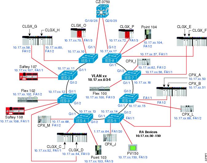
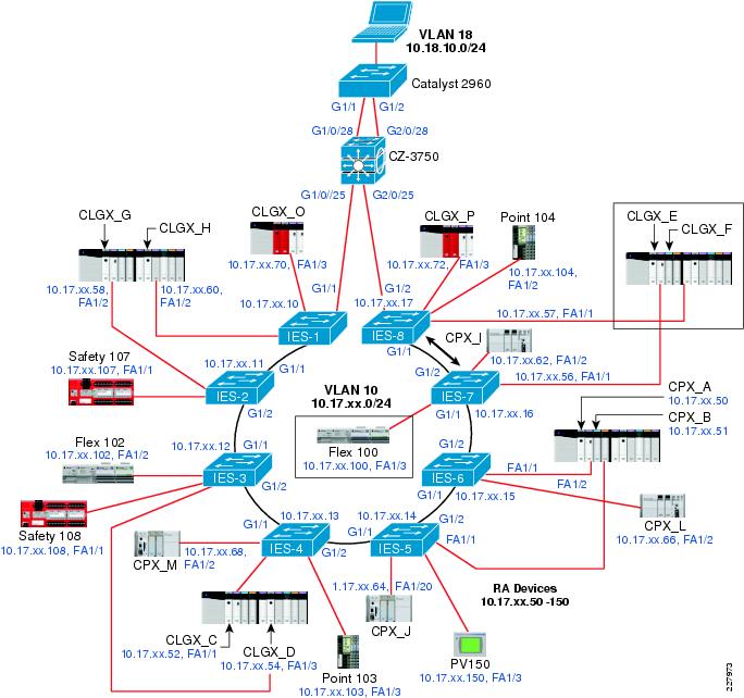
Figure 7-3 depicts the IACS devices and the network infrastructure for the Cell/Area zone in a ring topology that was used for testing network resiliency, application latency, and jitter.
Figure 7-3 IACS Devices and Network Infrastructure for Cell/Area Zone in Ring Topology
Test Measurements
This section describes the key measurements collected during the testing for CPwE, including network convergence and application sensitivity during network convergence.
Network Convergence
Network convergence is measured in the same manner as in Phase 1. The network traffic generator (see the "Test Equipment" section) generates bidirectional UDP unicast or multicast packet streams from two ports on the network topology. Each port both send packets to and capture packets from the other port. Two such streams are used to measure network convergence from different points in the topology. The test streams were ran for a set period of time, during which a topology change was executed (e.g., pull an uplink cable or port shutdown). Each port measure the number of packets received from the sending port. The convergence time is measured using the following formula:
Convergence in milliseconds = [(Tx - Rx) / packet rate] * 1000 ms/s
Where:
Tx = Packets transmitted
Rx = Packets received
Packet rate = 10,000 packets per second
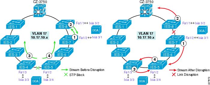
Typically, the network resiliency test collects network convergence from four streams of data. Figure 7-4 shows an example of the streams in a ring topology. The same switches and ports were used in the redundant star topologies.
Figure 7-4 Network Resiliency Test Streams - Ring topology
Table 7-5 lists the network resiliency test streams.
Table 7-5 Network Resiliency Test Streams
Test Stream
|
Origin
|
Ingress Switch
|
Egress Switch
|
Destination
|
Stream 1
|
Ixia 3/1
|
IES-7
|
IES-8
|
Ixia 3/2
|
Steam 2
|
Ixia 3/2
|
IES-8
|
IES-7
|
Ixia 3/1
|
Stream 3
|
Ixia 3/3
|
IES-4
|
IES-5
|
Ixia ¾
|
Stream 4
|
Ixia ¾
|
IES-5
|
IES-4
|
Ixia 3/3
|
In "Complete Test Data,"each test suite has a topology diagram with the test streams indicated.
As noted, there were two types of test streams used to calculate network convergence: unicast and multicast UDP. The UDP unicast stream more closely represents peer-to-peer traffic. The UDP multicast stream more closely represents implicit I/O traffic. For a number of reasons, network convergence based on multicast streams was measured only in redundant star configurations where EtherChannel or FlexLinks was the resiliency protocol. As Spanning Tree does not recover unicast or multicast traffic in the timeframe to support any type of I/O traffic, peer-to-peer or Implicit I/O, network convergence for multicast streams was not measured in any of the Spanning Tree test suites.
Application Sensitivity
The tests are designed to measure three types of application flows. These flows are commonly designed into automation and control systems. These flows are used to measure the impact network disruption and resulting network convergence has on the application traffic flow.
•
HMI (explicit)—Where communication is established between controllers and HMI devices. The flow is designed to not disrupt in network disruptions of under 20 seconds. This is an example of information/process traffic as described in the "Real-Time Communication, Determinism, and Performance" section.
•
Peer-to-peer (implicit unicast) represents communication between controllers that is typically passed via UDP unicast packets. This flow was designed to not disrupt in network disruptions of under 100 ms. This is an example of time critical traffic as described in the "Real-Time Communication, Determinism, and Performance" section.
•
Implicit I/O (implicit multicast) represents communication between controllers and I/O devices and drives that is typically passed via UDP multicast packets. This flow was designed to not disrupt in network disruptions of under 100 ms. This is an example of time critical traffic as described in the "Real-Time Communication, Determinism, and Performance" section.
These traffic flows represent the type of IACS data and network traffic that is handled by the network infrastructure. If any of the operational devices were to have a communication fault, the IACS application would display the controller and flag at fault. Traffic types 2 and 3 are relatively similar in that they both timeout at around 100 ms and are both based upon UDP traffic. The difference between them was whether unicast or multicast communication modes were used to communicate the data. In all network resiliency test cases, the IACS application was operational and communicating data. Therefore, the base test case has the following:
•
21 IACS devices on the network
•
Producing 80 streams of data (90 multicast groups)
In the current IACS application, only one of the implicit traffic types, peer-to-peer or Implicit I/O traffic flows are operational during a test run. Cisco and Rockwell Automation choose to operate the Implicit I/O traffic flow for the redundant star topologies.
The tests were designed to measure whether or not the application times out when a network fault or restoration is introduced, indicating whether the network converged fast enough to have the application avoid faulting. These test results are included in the appendices.
Test Organization
This section describes the organization of the network resiliency testing. First, there is a description of the test variables. This is a summary of the key variables that the network resiliency tests took into consideration. Second, there is a description of the test suites. A test suite in this case is a network topology and configuration. For each test suite, a variety of test cases were executed. For each test case, a number of test runs were executed for a variety of inserted MAC addresses to simulate additional end-devices. Each test run was executed with the IACS application in operation and measuring whether any controller lost a connection during the test run.
Test Variables
Table 7-6 outlines the key test variables incorporated into the CPwE testing.
Table 7-6 CPwE Network Resiliency Test Variables
Variable
|
|
EttF Phase 1
|
CPwE (Phase 2)
|
|
# of Options
|
Options
|
#Options
|
Options
|
Resiliency protocols
|
1
|
Rapid PVST+
|
2
|
MSTP, Rapid PVST+
|
Switch Composition
|
1
|
2955
|
2
|
IE 3000 & Stratix 8000
|
Size of the ring
|
2
|
8, 16
|
2
|
8, 16
|
# of Mac addresses
|
3
|
Base, 200, 400
|
3
|
Base, 200, 400
|
# of Network Events
|
8
|
4 failures and 4 restores
|
8
|
4 failures and 4 restores
|
Physical Layer
|
1
|
Copper
|
2
|
Copper and Fiber uplinks
|
Application Traffic type
|
0
|
Application data not collected
|
2 sets
|
HMI & Peer-to-peer
HMI & Implicit I/O
|
Test Runs
|
3
|
3 runs were measured per test case
|
5 or 10
|
Convergence tests were run 10 times for 8-Ring tests and 5 times for 16-ring tests
|
Network Convergence measurement type
|
1
|
UDP Unicast
|
2
|
UDP unicast and multicast
|
Test Suites
The test suite represents a network topology, resiliency protocol, and uplink media-type. Table 7-7 lists the test suites performed.
Table 7-7 CPwE Network Resiliency Test Suites
Test Suite
|
Topology
|
Resiliency Protocol
|
Uplink Physical layer
|
# of IE switches
|
Network Convergence measurement
|
RMC8
|
Ring
|
MSTP
|
Copper
|
8
|
UDP Unicast
|
RMC16
|
Ring
|
MSTP
|
Copper
|
16
|
UDP Unicast
|
RPC8
|
Ring
|
Rapid-PVST+
|
Copper
|
8
|
UDP Unicast
|
RMF8
|
Ring
|
MSTP
|
Fiber
|
8
|
UDP Unicast
|
SMC8
|
Redundant Star
|
MSTP
|
Copper
|
8
|
UDP Unicast
|
SMF8
|
Redundant Star
|
MSTP
|
Fiber
|
8
|
UDP Unicast
|
SEC8
|
Redundant Star
|
EtherChannel
|
Copper
|
8
|
UDP Unicast & multicast
|
SEF8
|
Redundant Star
|
EtherChannel
|
Fiber
|
8
|
UDP Unicast & multicast
|
SFC8
|
Redundant Star
|
Flex Links
|
Copper
|
8
|
UDP Unicast & multicast
|
SFF8
|
Redundant Star
|
Flex Links
|
Fiber
|
8
|
UDP Unicast & multicast
|
Note the naming convention:
•
First letter is for topology where R is for ring and S for redundant star.
•
Second letter is for resiliency protocol where M is for MSTP, P is for RPVST+, E is for EtherChannel, and F is for Flex Links.
•
Third letter is for uplink media type where C is for Cat 5E copper (Cat 5E or 6) cabling and F is for fiber.
•
The last number is for the number of switches in the topology, 8 or 16.
Test Cases
For each test suite, a variety of test cases were executed. A test case represents a type of network event, either a disruption or restoration. Table 7-8 describes the test cases executed. For each test case, a number of test runs were performed with varying amounts of simulated end-devices coming from the network generator. The eight cases of network disruption shown in Table 7-8 are performed.
Table 7-8 Test Cases
Test Case
|
Action
|
Network Response
|
Bring specified link down (software)
|
Virtually shut down the port by executing the "shut" command in CLI
|
Resiliency protocol perform a topology change and divert traffic over functional path
|
Bring specified link up (software)
|
Virtually restore the port by executing the "no shut" command in CLI
|
Recognize restored connection and depending on the protocol, execute a topology change and divert traffic over new functional path (Spanning Tree and EtherChannel only)
|
Disconnect specified Cable (physical)
|
Physically disconnect the cable
|
Resiliency protocol perform a topology change and divert traffic over functional path
|
Reconnect specified Cable (physical)
|
Physically restore the connection
|
Recognize restored connection and depending on the protocol, potentially execute a topology change and divert traffic over new functional path (Spanning Tree and EtherChannel)
|
Root bridge down (physical)
|
Virtually shut both Cell/Area ports on the distribution switch
|
Only performed for Ring/Spanning Tree test suites. Resiliency protocol performs a topology change and diverts traffic over functional path. New IGMP querier and root bride must be elected.
|
Root bridge up (physical)
|
Virtually restore both Cell/Area ports on the distribution switch
|
Only performed for Ring/Spanning Tree test suites. Recognize restored connections and execute a topology change and divert traffic over new functional path. Revert IGMP querier and root bridge functions to distribution switch
|
Stack Master down
|
Reload (reboot) the switch master in the stack
|
Resiliency protocol performs a topology change and diverts traffic over functional path. Stack Master, root bridge, and IGMP querier functions taken over by surviving switch.
|
Return Switch to Stack
|
With manual boot enabled, reboot the reloaded switch.
|
Except for Flex Links, resiliency protocol performs a topology change and diverts traffic over functional path. Stack Master, root bridge, and IGMP querier functions remain.
|
 |
Note The root bridge up/down test cases were only executed in the ring topology test suites. In a redundant star, the root bridge down represents a catastrophic failure where the network is no longer viable.
|
In nearly all cases, some network disruption is expected. The exception was with Flex Links that places a restored connection into standby mode, which has no noticeable impact on the traffic flows.
Summary
Table 7-9 lists all the test suites and test cases that were executed for the network resiliency portion of the CPwE test.
Table 7-9 Test Suites and Cases
Topology
|
Ring
|
Redundant Star
|
# of switches:
|
8 switches
|
16 switches
|
8 Switches
|
Resiliency Protocol:
|
MSTP
|
Rapid PVST+
|
MSTP
|
MSTP
|
EtherChannel
|
Flex Links
|
Uplink Media Type:
|
Copper
|
Fiber
|
Copper
|
Cooper
|
Copper
|
Fiber
|
Copper
|
Fiber
|
Copper
|
Fiber
|
SW Link disruption
|
RMC8-1
|
RMF8-1
|
RPC8-1
|
RMC16-1
|
SMC8-1
|
SMF8-1
|
SEC8-1
|
SEF8-1
|
SFC8-1
|
SFF8-1
|
SW Link restore
|
RMC8-2
|
RMF8-2
|
RPC8-2
|
RMC16-2
|
SMC8-2
|
SMF8-2
|
SEC8-2
|
SEF8-2
|
SFC8-2
|
SFF8-2
|
Physical Link disruption
|
RMC8-3
|
RMF8-3
|
RPC8-3
|
RMC16-3
|
SMC8-3
|
SMF8-3
|
SEC8-3
|
SEF8-3
|
SFC8-3
|
SFF8-3
|
Physical Link restore
|
RMC8-4
|
RMF8-4
|
RPC8-4
|
RMC16-4
|
SMC8-4
|
SMF8-4
|
SEC8-4
|
SEF8-4
|
SFC8-4
|
SFF8-4
|
Root Bridge down
|
RMC8-5
|
|
RPC8-5
|
RMC16-5
|
|
|
|
|
|
|
Root Bridge restore
|
RMC8-6
|
|
RPC8-6
|
RMC16-6
|
|
|
|
|
|
|
Stack Master down
|
RMC8-7
|
|
RPC8-7
|
RMC16-7
|
SMC8-5
|
SMF8-5
|
SEC8-5
|
SEF8-5
|
SFC8-5
|
SFF8-5
|
Stack Master restore
|
RMC8-8
|
|
RPC8-8
|
RMC16-8
|
SMC8-6
|
SMF8-6
|
SEC8-6
|
SEF8-6
|
SFC8-6
|
SFF8-6
|
Not all test cases were executed for each topology for the following reasons:
•
Root bridge up/down test cases were only executed in ring topology test suites. In a redundant star, the root bridge down represents a catastrophic failure where the network is no longer viable.
•
Uplink media type only has an impact on the link disruption test cases. Therefore, the Root Bridge and StackMaster tests were not completed for test suite RMF8.
Application-Level Latency and Jitter (Screw-to-Screw)
Screw-to-screw testing exposes how long it takes an I/O packet of data to make a round trip through the IACS hardware and network architecture, in other words application latency. By comparing these test results in various scenarios, the impact of network latency on the application latency is highlighted.
The approach of this test is to operate the screw-to-screw test in each of the test suites identified in the network resiliency test under two scenarios; short-path and long-path. In the short-path case, no network faults are in place and the I/O traffic will pass between 2 or 3 switches depending on the topology. In the long-path scenario, a fault already in place will divert the I/O traffic over the long-path. The resulting differences in application latency from the short-path and long-path scenarios, in theory, are then attributable to the additional switches in the network path. The application latency test results will be summarized later in this chapter and analyzed in "Test Result Analysis."
This section covers the following:
•
Test cases executed for the screw-to-screw test
•
IACS application describing the screw-to-screw test from an application perspective
•
Test measurements describing how the application latency is measured
Test Cases
This screw-to-screw test was conducted on the same test suites identified in the network resiliency test. This section highlights the short path and long path scenario in a 8-switch ring topology.
Short Path
Communication between the relevant IO and controller is between adjacent switches with an active link as shown in Figure 7-5.
Figure 7-5 Short Path
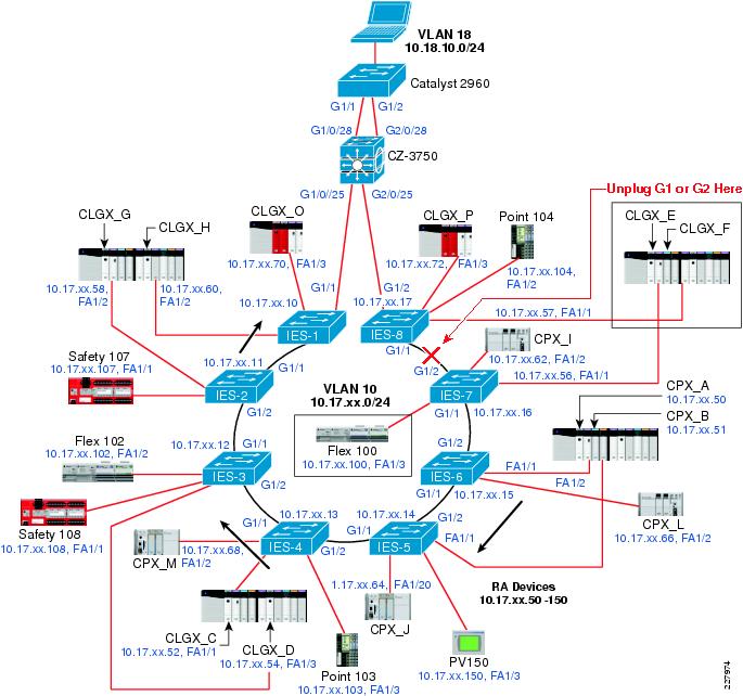
Long Path
Communication between the relevant IO and controller traverses the ring of network switches when link between adjacent switches is disrupted, as show in Figure 7-6.
Figure 7-6 Long Path
Table 7-10 lists the data for the screw-to-screw test performed.
Table 7-10 Screw-to-Screw
Test Suite
|
Short
|
Long
|
RMC8
|
X
|
X
|
RMC16
|
X
|
X
|
RPC8
|
X
|
X
|
RMF8
|
X
|
X
|
SMC8
|
X
|
X
|
SMF8
|
X
|
X
|
SEC8
|
X
|
X
|
SEF8
|
X
|
X
|
 |
Note Tests with Flex Links were not performed as there were no significant path differences.
|
IACS Application
The screw-to-screw test is essentially measuring communication between a controller (CLGX_F) and an EtherNet/IP (EIP) connected I/O device (Flex I/O 100). The communication takes two paths, one via the EIP network modules and the IACS network, the other via direct hardwire connections. This section describes the I/O paths and hardwire path.
I/O Packet Path
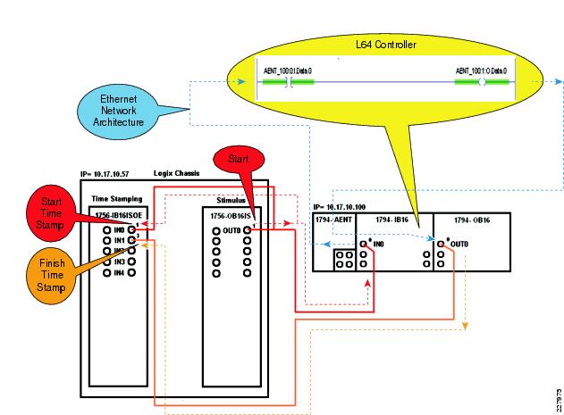
The I/O packet of data is in the form of a 24vdc pulse. The 24vdc pulse will be time stamped when it is first sent and will be time stamped after it travels through the hardware and architecture as shown in Figure 7-7.
A 24vdc pulse is generated from the 1756-OB16IS module. This 24vdc pulse will take two paths:
•
Path 1—The 1756-IB16ISOE module is used to timestamp when the 24vdc pulse is first generated by the 1756-OB16IS module, registering on IN0 of the 1756-IB16ISOE module, and when the 24vdc pulse has been generated by the 1794-OB16 module. These will be the start and finish time stamps that will be compared to help us understand how long it takes this 24vdc pulse to travel through the hardware and network architecture.
•
Path 2—The 1794-IB16 module is used to register this 24vdc pulse as an input condition into the L64 controller.
The 24vdc pulse is registered by the 1794-IB16 module and is sent every 10ms to the L64 controller in the form of an I/O packet of data via the 1794-AENT module and network architecture.
Once the I/O packet of data arrives in the L64 Controller, the 1794-IB16 input point IN0 will register as a value of (1) or a High signal (AENT_100:0:I.Data.0) and through Ladder Application Code will drive an output instruction (AENT_100:1:O.Data.0). This output packet of data will be sent back through the network architecture, back through the 1794-AENT module every 10ms and turn on the output point OUT0 on the 1794-OB16 module.
The 24vdc pulse generate (passed on) by the 1794-OB16 module will finish its travels by registering as a time stamp on the 1756-IB16ISOE module input IN1.
Figure 7-7 I/O Packet Path
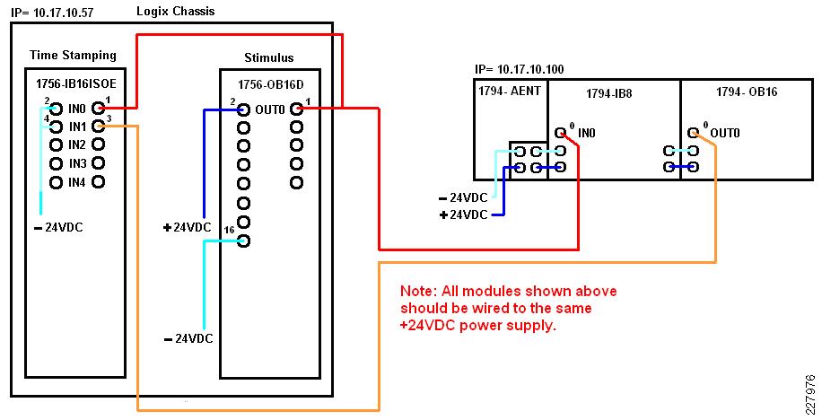
Hardware Wiring
The 1756 and 1794 modules are wired as shown in Figure 7-8.
Figure 7-8 Hardware Wiring
Test Measurements
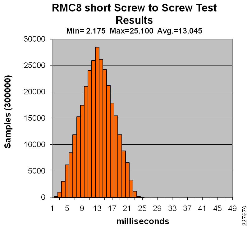
In this test, the IACS application measures the amount of time it takes to transmit a piece of information from the controller to the IO module via the EtherNet/IP network versus directly transmitting the information via hardwires between the IO module and controller, the SOE Time Stamp Difference Test Data. The time stamp difference is recorded in millisecond (ms) increments, for example if the SOE Time Stamp Data value received from the controller is 2.438 this value falls between 2 and 3ms so the 2ms bucket will get a value of (1) added to its field. If the SOE Time Stamp Data value is 10.913 this value falls between 10 and 11ms so the 10ms bucket will get a value of (1) added to its field. Based on this data, a minimum, maximum, and averages value are calculated. The average time stamp difference represents the average application latency. Each test run collected 300,000 samples and took about 8 to 10 hours to collect.
Figure 7-9 represents an example set of test results from screw-to-screw test run.
Figure 7-9 Test Results from an 8-switch Ring topology with MSTP and copper uplinks, Short-path
Test Execution
This section describes the key steps performed to execute the tests conducted for CPwE. The two key test types are network resiliency and application latency and jitter.
Network Resiliency
This section describes the test case execution for the network resiliency testing. Note that this section describes the test cases for the ring topology. Some minor modifications to these must be done for redundant star topology, notably that the link disrupted (virtually or physically) is between the IES-8 and 3750-stack switches, as all the industrial Ethernet switches were connected to the distribution switch in this test suite.
This section does not describe the setup steps as we followed the design and implementation recommendations for Cell/Area zones described in Chapter 3 "CPwE Solution Design—Cell/Area Zone" and Chapter 5 "Implementing and Configuring the Cell/Area Zone."
Test Cases
Eight tests cases were outlined for the network resiliency test. Table 7-11 to Table 7-18 list the steps to execute these test cases. The tables apply to the 8-switch ring, MSTP, copper-uplinks test suite. The steps were slightly varied for the redundant star topology, for example, the link between IES-8 and the distribution switch was disconnected/shutdown or reconnected for test cases 1 through 4.
Table 7-11 Test Case RMC8-1
Test Case RMC8-1
|
Bring the connection between IES-7 and IES-8 down and capture convergence times
|
Test Procedures
|
1. Verify that Switch 1 of the 3750 stack is the Stack Master
Switch# Role Mac Address Priority Version State
---------------------------------------------------------
*1 Master 001a.6d5f.ef80 15 0 Ready
2 Member 001a.6d5f.e380 2 0 Ready
2. Verify that the 3750 Stack is root and that before the failure, STP is blocking between IES-4 and IES-5
IES-5#show spanning-tree mst
##### MST0 vlans mapped: 1-4094
Bridge address 0021.1c30.8a00 priority 32768 (32768 sysid 0)
Root address 001a.6d5f.e380 priority 24576 (24576 sysid 0)
Regional Root address 001a.6d5f.e380 priority 24576 (24576 sysid 0)
internal cost 80000 rem hops 16
Operational hello time 2, forward delay 15,max age 20,txholdcount 6
Configured hello time 2, forward delay 15,max age 20,max hops 20
Interfac Role Sts Cost Prio.Nbr Type
------------ ---- --- --------- -------- ----------
Gi1/1 Altn BLK 20000 128.1 P2p
Gi1/2 Root FWD 20000 128.2 P2p
Fa1/1 Desg FWD 200000 128.3 P2p Edge
Fa1/2 Desg FWD 200000 128.4 P2p Edge
Fa1/3 Desg FWD 200000 128.5 P2p Edge
Fa1/4 Desg FWD 200000 128.6 P2p Edge
Fa2/1 Desg FWD 200000 128.7 P2p Edge
3. From the CLI of IES-8, identify the switch port connecting to IES-7
4. Prepare Ixia by Clearing All Statistics
5. Click on the Start Transmit button on the IXIA
6. From IES-8, shutdown the port connecting From IES-7
IES-8(config)#interface gigabitEthernet 1/1
IES-8(config-if)#shutdown
7. Wait for the test to complete
8. Document results
|
Expected Results
|
• When a failure occurs between IES-7 and IES-8, the connection between IES-4 and IES-5 should go to forwarding traffic.
• The IXIA streams should measure network convergence, for STP times >100 ms are expected
• The peer-to-peer application sensitivity measurement should register as the application times-out and restores connections when network convergence is complete.
|
Table 7-12 Test Case RMC8-2
Test Case RMC8-2
|
Restore the connection between IES-7 and IES-8 back up and capture convergence times
|
Test Procedures
|
1. From the CLI of IES-8, identify the switch port connecting to IES-7.
2. Prepare Ixia by Clearing All Statistics.
3. Click on the Start Transmit button on the IXIA
4. From IES-8, enable the port connecting From IES-7
IES-8(config)#interface gigabitEthernet 1/1
IES-8(config-if)#no shutdown
5. Wait for the test to complete.
6. Document results.
|
Expected Results
|
• When the link between IES-7 and IES-8 is restored Spanning Tree should be once again blocking between IES-4 and IES-5.
• The IXIA streams should measure network convergence, for STP times > and < 100ms are expected.
• The peer-to-peer application sensitivity measurement may register as the application times-out and restores connections when network convergence is complete.
|
Table 7-13 Test Case RMC8-3
Test Case RMC8-3
|
Physically Disconnect IES-7 and IES-8 and capture convergence times
|
Test Procedures
|
1. Verity that before the failure, STP is blocking between IES-4 and IES-5.
2. From the CLI of IES-8, identify the switch port connecting to IES-7.
3. Prepare Ixia by Clearing All Statistics.
4. Click on the Start Transmit button on the IXIA.
5. Disconnect the cable between IES-7 and IES-8.
6. Wait for the test to complete.
7. Document results.
|
Expected Results
|
• When a failure occurs between IES-7 and IES-8, the connection between IES-4 and IES-5 should go to forwarding traffic.
• The IXIA streams should measure network convergence, for STP times >100 ms are expected.
• The peer-to-peer application sensitivity measurement should register as the application times-out and restores connections when network convergence is complete.
|
Table 7-14 Test Case RMC8-4
Test Case RMC8-4
|
Reconnect the cable between IES-7 and IES-8 back up and capture convergence times
|
Test Procedures
|
1. Prepare Ixia by Clearing All Statistics.
2. Click on the Start Transmit button on the IXIA.
3. Reconnect the cable between IES-7 and IES-8.
4. Wait for the test to complete.
5. Document results.
|
Expected Results
|
• When the link between IES-7 and IES-8 is restored Spanning Tree should be once again blocking between IES-4 and IES-5.
• The IXIA streams should measure network convergence, for STP times > and < 100ms are expected.
• The peer-to-peer application sensitivity measurement may register as the application times-out and restores connections when network convergence is complete.
|
Table 7-15 Test Case RMC8-5
Test Case RMC8-5
|
Disconnect the Root Switch (3750)
|
Test Procedures
|
1. Verify that Switch 1 of the 3750 stack is the Stack Master and root.
Switch# Role Mac Address Priority Version State
---------------------------------------------------------
*1 Master 001a.6d5f.ef80 15 0 Ready
2 Member 001a.6d5f.e380 2 0 Ready
2. Verity that before the failure, STP is blocking between IES-4 and IES-5.
3. Prepare Ixia by Clearing All Statistics.
4. Click on the Start Transmit button on the IXIA.
5. Virtually shut the links between the CZ-37500 and IES-1 and IES-8.
CZ-C3750-1(config)#interface range GigabitEthernet 1/0/5, GigabitEthernet
2/0/5
CZ-C3750-1(config-if-range)#shutdown
Gig 1/0/5 is connected to IES-1
Gig 2/0/5 is connected to IES-8
6. Wait for the test to complete.
7. Document results.
|
Expected Results
|
• When the root switch is disconnected, a STP convergence takes place and a new switch needs to be elected as the new root.
• The connection between IES-4 and IES-5 should go to forwarding traffic.
• The IXIA streams should measure network convergence, for STP times >100 ms are expected.
• The peer-to-peer application sensitivity measurement should register as the application times-out and restores connections when network convergence is complete.
|
Table 7-16 Test Case RMC8-6
Test Case RMC8-6
|
Reconnect the Root Switch (3750)
|
Test Procedures
|
1. Prepare Ixia by Clearing All Statistics.
2. Click on the Start Transmit button on the IXIA.
3. Virtually restore the links between the CZ-37500 and IES-1 and IES-8.
CZ-C3750-1(config)#interface range GigabitEthernet 1/0/5, GigabitEthernet
2/0/5
CZ-C3750-1(config-if-range)# no shutdown
Gig 1/0/5 is connected to IES-1
Gig 2/0/5 is connected to IES-8
4. Wait for the test to complete.
5. Document results.
|
Expected Results
|
• When the connections are restored, the 3750 stack regains the role of STP root and IGMP querier.
• The connection between IES-4 and IES-5 is once again blocked.
• The IXIA streams should measure network convergence, for STP times > and < 100ms are expected.
• The peer-to-peer application sensitivity measurement may register as the application times-out and restores connections when network convergence is complete.
|
Table 7-17 Test Case RMC8-7
Test Case RMC8-7
|
Bring Stack Master Down
|
Test Procedures
|
1. Configure the stack to boot manually during the next boot cycle.
2. Identify the Stack Master in the 3750 stack. In this case, Switch #1 is the master.
Switch# Role Mac Address Priority Version State
---------------------------------------------------------
*1 Master 001a.6d5f.ef80 15 0 Ready
2 Member 001a.6d5f.e380 2 0 Ready
3. Verity that before the failure, STP is blocking between IES-4 and IES-5.
4. Prepare Ixia by Clearing All Statistics.
5. Click on the Start Transmit button on the IXIA.
6. Reload the Stack Master. In this case, Slot #1, Switch #1 is the master.
7. Wait for the test to complete.
8. Document results.
|
Expected Results
|
• When the Stack Master fails, a new switch needs to be elected as the Stack Master and a connection fails, creating a STP event and to re-elect a new STP root.
• The connection between IES-4 and IES-5 will go to forwarding traffic.
• The IXIA streams should measure network convergence, for STP times >100 ms are expected.
• The peer-to-peer application sensitivity measurement should register as the application times-out and restores connections when network convergence is complete.
|
Table 7-18 Test Case RMC8-8
Test Case RMC8-8
|
Add the switch back to the stack
|
Test Procedures
|
1. Prepare Ixia by Clearing All Statistics.
2. Click on the Start Transmit button.
3. Boot up the switch.
switch: boot
flash:/c3750-advipservicesk9-mz.122-46.SE/c3750-advipservicesk9-mz.122-46.SE.
bin
4. Wait for the test to complete.
5. Document results.
|
Expected Results
|
• Since there is already a Stack Master switch, no changes will take place to the stack, but the connection will be restored.
• When the link is restored Spanning Tree will be once again blocking between IES-4 and IES-5.
• The IXIA streams should measure network convergence, for STP times > and < 100ms are expected.
• The peer-to-peer application sensitivity measurement may register as the application times-out and restores connections when network convergence is complete.
|
Application-level Latency and Jitter
The application-level latency tests or screw-to-screw were performed on the above discussed test suites. Two test cases were performed: a short and long path. The long-path test case was executed after introducing a failure in the topology and then conducting the test run. An Excel spreadsheet with embedded macros was developed to start the test and collect the application latency statistics. The other IACS devices and applications were in operations during the test. No Ixia traffic generation was introduced or measured during these tests.
Test Results Summary
This section summarizes the key findings from the tests performed. This section is intended to summarize observations made from the test analysis documented in "Test Result Analysis" and "Complete Test Data." Some of the findings were included in earlier chapters to support key recommendations. The key objectives set forth for this test plan included to test and measure impact of the following:
•
Network scalability in terms of the number of switches and number of end-devices, in particular the impact of a larger network on network convergence
•
Media, in particular the use of fiber versus copper for inter-switch uplinks
•
Network topology (ring versus redundant star)
•
Network resiliency protocol, in particular between Spanning Tree versions, EtherChannel, and Flex Links
•
Network behavior in a variety of failure/restore scenarios, so customers and implementers can make decisions about how to react and potentially when to restore failed links or devices, in terms of network convergence, application sensitivity and overall system latency and jitter.
The key observations can be summarized into the following points:
•
Scalability (number of switches)—The size of the ring impacts (slows down) the network convergence in link disruption (physical or software) and stack master down test cases, although with the variability due to the copper media, this impact is difficult to quantify.
•
Scalability (number of switches)—The number of switches in a redundant star did not have an impact on the network convergence.
•
Scalability (number of switches)—Number of switches in the different network topologies tested did not create a large difference in application-level latency (screw-to-screw)
•
Scalability (number of endpoints)—The number of endpoints tested had an impact on the Spanning Tree topologies, although this impact was less significant than either media or topology and therefore difficult to measure. There was no significant negative impact of the number of endpoints simulated in Flex Links or EtherChannel test suites.
•
Media—Fiber uplink topologies converged significantly faster and with less variability than copper uplink topologies, all other conditions the same. The signal loss is detected much more quickly with fiber media than with copper.
•
Topology—Redundant star topologies converged more quickly than ring topologies. This is due to the fact that a redundant star only has two uplinks (three switches) maximum in the path between any two endpoints.
•
Resiliency—EtherChannel and Flex Links are faster than Spanning Tree in redundant star topologies. EtherChannel and Flex Links with fiber uplinks converged fast enough to avoid "time-critical" application timeouts; i.e. consistent recovery in less than 100ms. EtherChannel convergence times approached or exceeded 100ms in a few cases, so some application timeouts may occur, but were not experienced in the testing, With the exception of ring with copper uplinks, all other topology and resiliency protocol combinations converged fast enough for information/process applications (i.e., generally the network recovers within 1000ms).
•
Resiliency—Flex Links had better network convergence than EtherChannel, especially with multicast traffic, in a range of test cases. This is due to the multicast fast convergence feature in FlexLinks.
•
Network Behavior—Restoring connections (physically or virtually) and restoring switches to the stack have little impact. Network convergence was often fast enough to avoid time-critical application timeouts. One notable exception was EtherChannel did have slow network convergence when a switch was restored to the stack.