-
Converged Plantwide Ethernet (CPwE) Design and Implementation Guide
-
Preface
-
Converged Plantwide Ethernet Overview
-
Converged Plantwide Ethernet Solution
-
CPwE Solution Design—Cell/Area Zone
-
Solution Design—Manufacturing and Demilitarized Zones
-
Implementing and Configuring the Cell/Area Zone
-
Plant Network Security and the Demilitarized Zone
-
Testing the CPwE Solution
-
CIP Motion
-
CIP Sync Sequence of Events
-
DHCP Persistence in the Cell/Area Zone
-
Key Terms and Definitions
-
Test Result Analysis
-
Complete Test Data
-
Configurations
-
Reference Documents
-
Table Of Contents
DHCP Persistence in the Cell/Area Zone
Using DHCP Persistence to Replace a Failed IACS Device
Using DHCP Persistence to Provision a New IACS Device
Brief Technology Overview of DHCP
Address Allocation in IACS Networks
DHCP Address Allocation (Handshake) Process
Methods of IP Allocation in DHCP
DHCP Persistence Reference Architectures Testing
DHCP Persistence Design Recommendations for IACS Devices
DHCP Persistence Configuration Techniques
DHCP Persistence Topology Considerations
DHCP Persistence in the Cell/Area Zone
Introduction
This chapter describes the implementation of Dynamic Host Configuration Protocol (DHCP) persistence on an Industrial Automation and Control System (IACS) network and extends the design recommendations described in Chapter 3, "CPwE Solution Design—Cell/Area Zone," Chapter 4, "CPwE Solution Design—Manufacturing and Demilitarized Zones," and Chapter 5, "Implementing and Configuring the Cell/Area Zone." Table 4-7 highlights several ways to allocate IP addresses and lists advantages and disadvantages of these methods. Cisco and Rockwell Automation recommend that IACS network developers use a static IP addressing schema for the Manufacturing zone, especially for allocating IP addresses to IACS devices in the Cell/Area zone. Cisco and Rockwell Automation now recommend DHCP Persistence as a valid option along with static addressing for deploying IP addresses for IACS devices.
As noted in earlier chapters, the Cell/Area zone is where the IACS devices connect into the Cell/Area IACS network. Careful planning is required to achieve the optimal design and performance from both the Cell/Area IACS network and IACS device perspective. This extension of the CPwE architectures focuses on EtherNet/IP, which is driven by the ODVA Common Industrial Protocol (CIP) (see the "IACS Communication Protocols" section on page 1-26). The EtherNet/IP protocol is tested with Rockwell Automation devices, IE switches, controllers, and applications.
Static IP addressing is the traditional, default means to allocate IP addresses for both IACS devices (for example, drives and I/O) and network infrastructure devices (for example, IE switches). Static IP addressing requires an implementer to manually configure an IP address on an IACS device as it is provisioned onto the IACS network. Static IP addressing is referenced directly (rather than a logical reference) by the IACS applications for communication and control purposes. Therefore, the IP addressing assigned must be consistent and defined for proper IACS application operation.
As IACS networks grow in size, so does the task of maintaining static IP addresses on IACS devices. During maintenance operations, where downtime cost and mean time to recovery (MTTR) is a significant issue, manual configuration of a static IP address for each replaced IACS device can take valuable time.
DHCP Persistence enables IACS implementers to reserve and pre-assign an IP address to a specific IE switch port. This enables an IACS device connected to that IE switch port, configured for dynamic IP allocation, to always receive a consistent IP address regardless of its MAC address. This capability helps to reduce the amount of time required to provision or replace IACS devices, such as drives and I/O. This also helps to reduce the required level of skilled resources to provision or replace an IACS device.
Although Cisco and Rockwell Automation now recommend DHCP Persistence as a valid option for IACS devices, Cisco and Rockwell Automation still recommend that network developers use a static IP addressing schema for IACS network infrastructure devices.
This chapter outlines the key requirements and technical considerations for DHCP Persistence within the Cell/Area zone. There are two typical use cases for implementing DHCP Persistence: replacement of a failed IACS device, and setting up a new "out-of-the-box" IACS device.
Using DHCP Persistence to Replace a Failed IACS Device
Consider the example of a municipal water distribution system that has multiple pumping stations located over a large geographic area. Often, these networks are tied together into a central location for monitoring purposes. Because of this centralization, it is convenient to have only a few network administrators who must maintain addressing for the entire system.
If an IACS device on a pumping station fails, maintenance staff on site could replace the IACS device. However, special training in all IACS products may be required to properly set IP addressing. If dynamic allocation is enabled on this IACS device, the maintenance staff would simply connect the new IACS device to the DHCP Persistence server (the IE switch to which the IACS device is connected), which allocates the correct IP address, enabling the maintenance staff to complete the IACS device configuration.
Using DHCP Persistence to Provision a New IACS Device
To reduce the amount of time necessary to configure a new system, Cisco and Rockwell Automation have enabled specific technology to allow a more efficient out-of-the-box experience when deploying IP-enabled devices in an IACS application. Manually configuring network addresses on IACS devices can add extra time and complexity to system setup. To configure DHCP, the following tasks must be performed:
•
Creating a DHCP pool
•
•
•
In a typical IACS application, in which the IACS network infrastructure supports DHCP Persistence, these steps can be skipped. All IACS devices that have DHCP/BOOTP enabled out-of-the-box require only that power be applied, and the switch be connected via the appropriate switch port so that the switch can communicate. This saves the user valuable configuration time. Other applications can be configured to download the operating system and configure the IACS device.
To configure these options on a Stratix 8000 or Stratix 8300 switch, see Rockwell Automation publication 1783-UM003, "Stratix 8000 and Stratix 8300 Ethernet Managed Switch User Manual", at the following URL:
http://literature.rockwellautomation.com/idc/groups/literature/documents/um/1783-um003_-en-p.pdf
Brief Technology Overview of DHCP
Following is a brief description of DHCP.
Address Allocation in IACS Networks
DHCP is an auto-configuration protocol used in IP networks. DHCP allows the IP address, subnet mask, and default gateway of any node to be configured automatically from a central server.
The primary reason for using DHCP on an IACS network is to allow server (IE switch) management of addressing. Because a server manages IP address allocation, it is unnecessary to configure IACS device addresses. This can save significant configuration time during maintenance. Until recently, the downside of DHCP has been that the process may not always deliver an IP address or the same IP address to the same device. DHCP Option 82 was created to help this situation by enabling DHCP to consistently deliver the same IP address to a device based on criteria such as MAC address. This mechanism does not cover replacing devices nor does it guarantee consistent delivery, because it relies on a server or device to maintain the IP-to-MAC address table. Another device configured as a DHCP server, known as a rogue DHCP server, may respond to requests.
As part of the ODVA Standard for EtherNet/IP, it is required that all complying devices are able to have an address issued via DHCP or BOOTP "out-of-the-box". Because of this, all Rockwell Automation EtherNet/IP enabled devices have BOOTP enabled by default.
For more information on the ODVA standard for EtherNet/IP, visit http://www.odva.org.
DHCP Address Allocation (Handshake) Process
The DHCP address allocation process is as follows:
•
•
•
•
Methods of IP Allocation in DHCP
Depending on the implementation, the DHCP server may have four methods of allocating IP addresses:
•
•
•
•
For detailed Stratix 8000 switch DHCP Persistence behavior, see Rockwell Automation publication 1783-UM003, "Stratix 8000 and Stratix 8300 Ethernet Managed Switch User Manual", at the following URL:
http://literature.rockwellautomation.com/idc/groups/literature/documents/um/1783-um003_-en-p.pdf
For detailed Stratix 6000 switch DHCP per port behavior, see Rockwell Automation publication 1783-UM001, "Stratix 6000 Ethernet Managed Switch User Manual", at the following URL:
http://literature.rockwellautomation.com/idc/groups/literature/documents/um/1783-um001_-en-p.pdf
DHCP vs. BOOTP
DHCP was developed as an extension of the Bootstrap Protocol (BOOTP), which is still in use in many EtherNet/IP-enabled IACS devices. Because of the close relationship between DHCP and BOOTP, most DHCP servers can also function as BOOTP servers.
This document does not describe the technical differences in the structuring of packets between DHCP and BOOTP. No differences in address allocation with respect to DHCP Persistence should occur, whether a client uses DHCP or BOOTP.
DHCP Snooping (Advanced Stratix 8000 Switch DHCP Feature)
DHCP Snooping is a feature applied to ensure the security of an existing DHCP infrastructure. DHCP Snooping prevents unauthorized DHCP servers from assigning addresses to clients. When DHCP Snooping is enabled on an IE switch, the switch uses a series of Layer 2 techniques to do the following:
•
•
•
This feature is available on Stratix 8000 and 8300 switches. This feature helps ensure the deterministic nature similar to static IP addressing by ensuring only the appropriate server (in this case the switch to which the end device is connected) assigns the IP address.
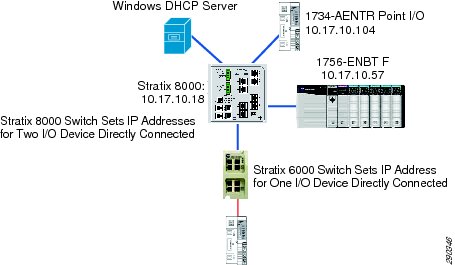
Figure 10-1 shows a sample topology with DHCP Snooping enabled on a Stratix 8000 switch.
Figure 10-1 Sample Topology With DHCP Snooping Enabled on a Stratix 8000 Switch
In this example, the Stratix 8000 switch is the DHCP server for both the Rockwell Automation 1756-ENBT and 1734-AENT modules. However, because both the distribution and Stratix 6000 switches act as DCHP servers also tied to the IACS network, multiple DHCP offers could be sent over the subnet. To prevent the 1734-AENT or 1756-ENBT modules from receiving incorrect addresses, DHCP Snooping is enabled on the Stratix 8000 switch.
Note
Table 10-1 lists additional information on topics related to DHCP.
DHCP Persistence Reference Architectures Testing
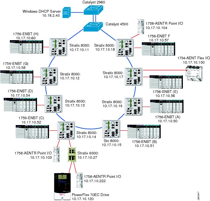
To ensure proper address assignment via DHCP Persistence, the large-scale reference architecture topology shown in Figure 10-2 was tested. The topology included eight Stratix 8000 switches connected in a ring to a Cisco Catalyst 4500 distribution switch. Each Stratix 8000 switch had DHCP-enabled IACS devices such as Rockwell Automation programmable controllers and I/O modules connected to it. In addition, to ensure that each IE switch acts as a DHCP server only to the IACS devices directly connected to it, the Stratix 6000 switch was added into the topology. A PowerFlex drive and Point I/O module were connected directly to the Stratix 6000 switch. The Windows DHCP Server was also added to act as an outside server to the system. If DHCP Snooping was performing as planned, the Windows server should not allocate any addresses to the end devices.
Note
Figure 10-2 Typical Large-scale Topology
Test Criteria
The tests were designed with the following criteria in mind:
•
•
•
Test Configuration
The test was configured as follows:
•
•
•
•
Note
•
•
•
•
Table 10-2 shows the Stratix 8000 and Stratix 6000 switch configurations.
Testing Procedure
As part of automated DHCP Persistence testing, the following procedure was observed.
Procedure
Step 1
Step 2
Step 3
Step 4
Step 5
Step 6
Although the automated test suite used a programmatic CIP reset message for power cycling, a manual power cycle test was added to verify the impact of an actual power cycle. Similar results were achieved through 25 manual power cycles. During the manual test the following procedure was observed:
Procedure
Step 1
Step 2
Step 3
Step 4
Step 5
Step 6
Step 7
Test Results
The automated test suite successfully completed over 1500 iterations of the test. The Stratix 8000 switches used DHCP Snooping and DHCP Persistence to ensure that the correct IP addresses were given to all IACS devices directly connected to the IE switch. The Stratix 6000 switch used DHCP Persistence to ensure that the correct IP addresses were given to all IACS devices directly connected to the IE switch.
The testing confirmed that all IACS devices successfully received the expected IP addresses as planned.
DHCP Persistence Design Recommendations for IACS Devices
Keep the following in mind when planning a system that uses DHCP Persistence for IP addressing.
•
For recommendations on IP addressing, see Chapter 4, "CPwE Solution Design—Manufacturing and Demilitarized Zones," and Table 4-7.
•
For additional information on setting up the Stratix 8000 switch, see Rockwell Automation publication, "Stratix 8000 and Stratix 8300 Ethernet Managed Switch User Manual", available at the following URL:
http://literature.rockwellautomation.com/idc/groups/literature/documents/um/1783-um003_-en-p.pdf
•
For additional information on setting DHCP Persistence, creating the DHCP pool of IP addresses, and enabling DHCP Persistence per port on the Stratix 8000 switch, see Rockwell Automation publication, "Stratix 8000 and Stratix 8300 Ethernet Managed Switch User Manual", available at the following URL:
http://literature.rockwellautomation.com/idc/groups/literature/documents/um/1783-um003_-en-p.pdf
•
For additional information on enabling DHCP Snooping on the Stratix 8000 switch, see Rockwell Automation publication, "Stratix 8000 and Stratix 8300 Ethernet Managed Switch User Manual", available at the following URL:
http://literature.rockwellautomation.com/idc/groups/literature/documents/um/1783-um003_-en-p.pdf
•
For additional information on setting DHCP Per Port on Stratix 6000 switch, see Rockwell Automation publication, "Stratix 6000 Ethernet Managed Switch User Manual", available at the following URL:
http://literature.rockwellautomation.com/idc/groups/literature/documents/um/1783-um001_-en-p.pdf
DHCP Persistence Configuration Techniques
Keep these techniques in mind as you configure your IACS application to use DHCP Persistence:
•
•
•
•
•
•
DHCP Persistence Topology Considerations
DHCP Persistence functionality is not affected by the IACS network topology in which it is applied. However, only one IACS device can be connected to an IE switch port. Regardless of the topology, the switch allocates IP addresses to all DHCP-enabled devices connected directly to it. However, there are several considerations to be pointed out for each topology.
Note
Linear Topology
In a linear topology, each IE switch should be configured with DHCP Persistence enabled to allow dynamic address allocation to all IACS devices attached to them. In Figure 10-3, every IACS device on the access link layer would have an IP address assigned by the IE switch to which it is attached. The IE switch would assign the address IP address by port. All IE switches are configured with their own static IP address for manageability purposes.
Figure 10-3 Linear Topology
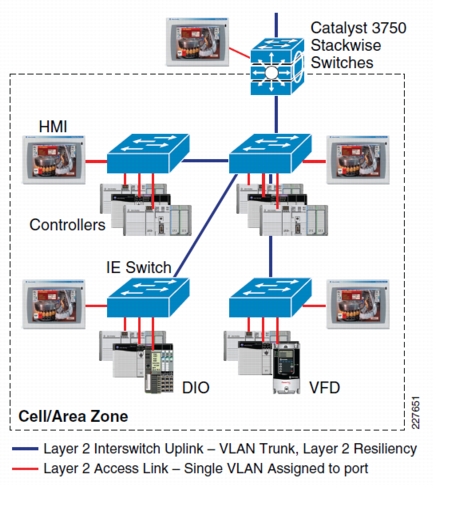
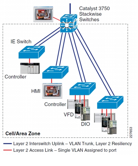
Star Topology
In a star topology, IACS devices on the access link layer receive their IP addresses from the IE switch to which they are attached. In this configuration (see Figure 10-4), the IE switch assigns addresses per port for the IACS devices connected to it.. All IE switches are configured with their own static IP address for manageability purposes. DHCP Snooping is enabled on all IE switches. This prevents the IACS device from receiving IP addresses from the wrong DHCP servers.
Figure 10-4 Star Topology
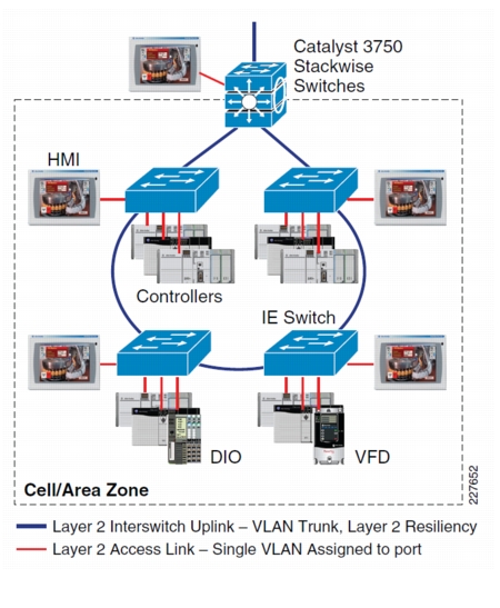
Ring Topology
In a ring topology (see Figure 10-5), much like the other topologies, it is necessary to set up DHCP Persistence on each IE switch with connected IACS devices. An IE switch on one side of the ring cannot serve IP addresses to IACS devices connected to another IE switch elsewhere on the ring with DHCP Snooping configured. All IE switches are configured with their own static IP address for manageability purposes.
Figure 10-5 Ring Topology
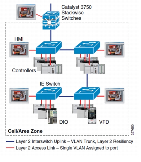
Redundant Star Topology
A redundant star topology (see Figure 10-6) requires configuration of DHCP Persistence on each IE switch. The resiliency provided between IE switches does not affect configuration of DHCP Persistence. All IE switches are configured with their own static IP address for manageability purposes.
Figure 10-6 Redundant Star Topology