-
Voice and Video Enabled IPSec VPN (V3PN) Solution Reference Network Design
-
Preface
-
V3PN SRND Introduction
-
V3PN Solution Overview and Best Practices
-
V3PN Solution Components
-
Planning and Design
-
Product Selection
-
Implementation and Configuration
-
Verification and Troubleshooting
-
Network Diagram Scalability Testbed and Configuration Files
-
Configuration Supplement--Voice Module, EIGRP Stub, DSCP, HDLC
-
Configuration Supplement--Dynamic Crypto Maps, Reverse Route Injection
-
Table Of Contents
Implementation and Configuration
Routing Protocol, Switching Path and IP GRE Considerations
EIGRP Summarization and Network Addressing
Configuration Example—512 Kbps Branch
WAN Implementation Considerations
WAN Aggregation Router Configuration
Frame Relay Traffic Shaping and FRF.12 (LFI)
Attach Service Policy to Frame Relay Map Class
Apply Traffic Shaping to the Output Interface
Applying Service Policy to HDLC Encapsulated T1 Interfaces
Combined WAN and IPSec/IP GRE Router Configuration—Cisco 7200 HDLC/HSSI
Configure ISAKMP Policy and Pre-shared Keys
Apply Crypto Map to Interfaces
Implementation and Configuration Checklist
Implementation and Configuration
This chapter provides step-by-step examples of how to configure the V3PN environment tested by Cisco Enterprise Solutions Engineering and is separated into the following principal sections:
•
Routing Protocol, Switching Path and IP GRE Considerations
•
The chapter ends with the "Implementation and Configuration Checklist" section.
The recommended approach would be to read through each section before implementing V3PN. If there are topics or concepts which are unclear, consult the associated design guides or documentation at Cisco's informational website at the following URL: http://www.cisco.com/en/US/netsol/ns742/networking_solutions_program_category_home.html . Then approach the first configuration with the Implementation and Configuration checklist and refer back to the specific section for examples.
Routing Protocol, Switching Path and IP GRE Considerations
This SRND assumes that the IP addressing scheme lends itself to summarization from the branch to the core, and that the core sends a default or summary route to the branch. Design considerations specific to this implementation are detailed in the following sections:
•
Configure Switching Path
In the Cisco Enterprise Solutions Engineering lab test, CEF was enabled on all routers under test. To enable CEF switching on the branch routers, verify or configure the ip cef command.
Configure IP GRE Tunnels
When configuring IP GRE tunnels, the most common issue is routing. The IP addresses selected for the tunnel end-points—the tunnel source and destination—must be reachable for the tunnel to come up. Additionally, when a routing protocol is configured on the tunnel interface, it must not advertise the network(s) represented by the tunnel end-points through the tunnel itself or the tunnel interface will be disabled and the following message is logged:
%TUN-5-RECURDOWN: Tunnel0 temporarily disabled due to recursive routingPlease see www.cisco.com for more information on configuring tunnel interfaces. Specifically, the document at the following URL contains information tunnel interfaces and routing: http://www.cisco.com/en/US/tech/tk365/technologies_tech_note09186a0080094690.shtml.
There is also a complete illustration in Appendix A, "Network Diagram Scalability Testbed and Configuration Files" of this publication.
To avoid problems when configuring IPSec, configure and verify both tunnel interfaces are up to the head-end IPSec/GRE head-end routers.
EIGRP Summarization and Network Addressing
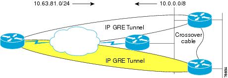
In this phase of Cisco Enterprise Solutions Engineering lab testing, EIGRP Stub support was not scale tested. The EIGRP Stub feature increases scalability and it will be incorporated into future full-scale testing. Optimized addressing and summarization are implemented in the design. With or without implementing EIGRP Stub support, proper summarization enhances network stability and performance. Just as IPSec increases the bandwidth requirements of voice packets, it also adds to the bandwidth required for routing protocol updates. Decreasing the number of routing updates that must be sent is under control of the network manager, and summarization is the tool used to implement that bandwidth savings. Figure 6-1 illustrates one method of IP addressing and EIGRP summarization.
Figure 6-1 IP Addressing and EIGRP Summarization
Branch routers advertise a manually summarized route on a 24 bit boundary via the tunnel interfaces to the core:
!interface Tunnel0ip summary-address eigrp 1 10.63.81.0 255.255.255.0 5!interface Tunnel1ip summary-address eigrp 1 10.63.81.0 255.255.255.0 5!Core routers advertise a manually summarized route on an 8-bit boundary via the tunnel interfaces to the branch routers:
!interface Tunnel240ip summary-address eigrp 1 10.0.0.0 255.0.0.0 5!The typical branch EIGRP configuration is shown below:
!router eigrp 1passive-interface Serial0/0.1passive-interface Ethernet0/1network 10.0.0.0no auto-summaryeigrp log-neighbor-changes!EIGRP hold-time
On 64 Kbps links in the Cisco Enterprise Solutions Engineering lab tests the hold-time on the tunnel interfaces was increased from the default of 15 seconds to 25 seconds to maintain EIGRP neighbor relationships in that event that three consecutive EIGRP hello packets were dropped.
!interface Tunnel0ip hold-time eigrp 1 25!The hello interval remained at the default of 5 seconds. While EIGRP hello packets have their PAK_PRIORITY bit set to indicate relative importance on the originating router, once EIGRP hello packets are encapsulated in IP GRE and IPSec headers, the only indication of significance to intermediate routers (ISP routers) is the IP Precedence of 6. This underscores the importance of using a QoS aware service provider.
IP GRE Tunnel Delay
The delay value was increased on the backup tunnel interface (Tunnel 1 on the branch routers) to influence path selection with EIGRP. The default delay value for a GRE tunnel interface is 500000 usec, to make one tunnel the backup interface the delay value was increase to 600000 usec. All traffic traverses the primary tunnel unless the head end device is unavailable. In the Cisco Enterprise Solutions Engineering lab test, there is only one physical interface and the tunnels are sourced off the physical interface. If there were two physical interfaces per branch, it would be preferable to source off loopback interfaces so both logical tunnels remain up in the event of a branch serial interface failure.
The show interface commands displays delay in microsecond units. The delay interface command specifies the delay metric, in 10 microsecond units. EIGRP calculates its metric from the minimum bandwidth in Kbps for all links in the path, and the cumulative delay in microseconds for all links in the path.
!vpn13-3640-2#show interface tunnel 0Tunnel0 is up, line protocol is upHardware is TunnelDescription: Tunnel0Internet address is 10.63.81.194/30MTU 1514 bytes, BW 9 Kbit, DLY 500000 usec,reliability 255/255, txload 255/255, rxload 255/255Encapsulation TUNNEL, loopback not setKeepalive not setTunnel source 192.168.217.2, destination 192.168.252.1Tunnel protocol/transport GRE/IP, key disabled, sequencing disabledTunnel TTL 255Checksumming of packets disabled, fast tunneling enabled!!interface Tunnel0description Tunnel0ip address 10.63.81.194 255.255.255.252ip hold-time eigrp 1 25ip summary-address eigrp 1 10.63.81.0 255.255.255.0 5load-interval 30tunnel source 192.168.217.2tunnel destination 192.168.252.1crypto map static-map!vpn13-3640-2#show interface tunnel 1Tunnel1 is up, line protocol is upHardware is TunnelDescription: Tunnel1Internet address is 10.63.81.198/30MTU 1514 bytes, BW 9 Kbit, DLY 600000 usec,reliability 255/255, txload 1/255, rxload 1/255Encapsulation TUNNEL, loopback not setKeepalive not setTunnel source 192.168.217.2, destination 192.168.251.1Tunnel protocol/transport GRE/IP, key disabled, sequencing disabledTunnel TTL 255Checksumming of packets disabled, fast tunneling enabled!!interface Tunnel1description Tunnel1ip address 10.63.81.198 255.255.255.252ip hold-time eigrp 1 25ip summary-address eigrp 1 10.63.81.0 255.255.255.0 5delay 60000tunnel source 192.168.217.2tunnel destination 192.168.251.1crypto map static-map!!interface Serial0/0.1 point-to-pointdescription Serial0/0.1ip address 192.168.217.2 255.255.255.252!QoS Configuration
Quality of Service (QoS) implementation topics covered in this chapter are:
•
Campus QoS—Mapping ToS to CoS
Use separate VLANs for voice and data when there is an option to segment the IP address space at the branch office. If the switch in use at the branch supports only Layer-2 services, no Layer-3, and supports 802.1Q trunking, then the branch WAN router should be configured to set the User Priority bits in the 802.1p portion of the 802.1Q header The set cos is only supported with IEEE 802.1Q/ISL interfaces.
The Cisco 800 series, 1720 and 1750 do not support 802.1Q, however the Cisco 2600 and 3600 series, as well as the Cisco 1710, 1751, 1760 and 1721 do support 802.1Q. The IP Plus feature set is needed to support 802.1Q trunking.
The following example should be used to supplement the configuration files from the lab test results.
!class-map match-all call-setupmatch ip precedence 3class-map match-any mission-criticalmatch ip precedence 2match ip precedence 6class-map match-all voicematch ip precedence 5class-map match-all user-mission-criticalmatch ip precedence 2!policy-map output-L3-to-L2class voiceset cos 5class call-setupset cos 3class user-mission-criticalset cos 2!interface FastEthernet0/1.201encapsulation dot1Q 201ip address 10.250.0.1 255.255.255.0service-policy output output-L3-to-L2!In this example, a user-mission-critical class is used to specify only the IP Precedence 2 mission critical traffic that is bound for the end-user's workstation via the branch router's Fast Ethernet interface. The combination of IP Precedence 2 and 6 traffic into the mission-critical was intended to provide a class for both end-user mission critical traffic as well as EIGRP hello/updates and other management traffic like SNMP, Telnet, NTP, etc. which are set to IP Precedence 6.
For additional information, refer to the Enterprise QoS Design Guidelines at the following URL: http://www.cisco.com/en/US/docs/solutions/Enterprise/WAN_and_MAN/QoS_SRND/QoS-SRND-Book.html
QoS Trust Boundary
In this design guide, it is assumed that the network manager is setting the IP Precedence/DSCP values appropriately so they match the service policy applied to the output interface. This can be done at the application level, or the Layer-2 switch at the remote and head-end. For the purpose of simplicity in our lab testing, it is assumed IP Precedence is marked by the application or Layer-2 switch. Cisco IP Phones set the IP precedence of the voice traffic to 5 (DSCP EF) and override the IP Precedence of data traffic from the switch port in the phone to 0.
Not all devices are attached to an IP Phone. An example would be a dedicated DLSw router at the branch or DLSw configured on the branch WAN router. It is extremely important to audit the applications in use against the policy-map implemented.
DLSw peers generate TCP traffic to/from port 2065 and by default DLSw sets IP Precedence to 5. In the DLSw configuration change this by using dlsw tos map, if priority peers are not configured, high is the only operative option. For example:
!dlsw local-peer peer-id 10.251.0.1dlsw remote-peer 0 tcp 10.254.0.45dlsw tos map high 2 medium 0 normal 0 low 0!Now DLSw is set to use IP Precedence of `2' and its traffic matches on the mission-critical entry, rather than the `voice' class, which it would if left to the default.
The "Using NetFlow to Verify ToS Values" section on page 7-6 presents an example of using NetFlow to verify the ToS byte values used by applications on the network.
Configure QoS Class Map
In order to configure a QoS Policy map, a class map must first be configured. The purpose of the class map is to define the packets associated with the named class of traffic. Just as each enterprise is different in the type and nature of its applications, so will the class map definition. The following configuration sample was used during lab testing.
!class-map match-all call-setupmatch ip precedence 3class-map match-any mission-criticalmatch ip precedence 2match ip precedence 6class-map match-all voicematch ip precedence 5!Expect to tune the class-map configuration during implementation. Business critical applications have a way of being overlooked until they don't work properly. In the above example, a mission-critical class was created and it includes both user mission critical applications (IP Precedence 2) and Internetwork Control or IP Precedence 6 traffic. Cisco telnet, BGP, EIGRP, OSPF, NTP, SNMP all use IP Precedence 6 and are included in this class. During testing, EIGRP hellos were being dropped—they defaulted to the class-default so IP Precedence 6 was included in the mission-critical class. Another approach would have been to create a distinct class for this traffic.
For example:
!class-map match-all call-setupmatch ip precedence 3class-map match-all mission-criticalmatch ip precedence 2class-map match-all internetwork-controldescription Routing hellos/updates, cisco telnet, SNMP, NTPmatch ip precedence 6class-map match-all voicematch ip precedence 5!However, this configuration was not scale tested in the lab. The amount of bandwidth to allocate to the internetwork-control class can vary depending on parameters such as the degree of summarization of routing protocol advertisements, the volume of SNMP, or telnet traffic. A suggested starting value is allocating five percent of the bandwidth to internetwork-control and increasing that as needed depending on the implementation.
The QoS Class Map must be configured on each organization's branch router. In addition, if a Layer-3 service provider is being used, the QoS Class Map must also be configured on the service provider's edge router.
For the central site, the QoS Class Map can be configured on either the enterprise head-end WAN aggregation routers (in the case of separate WAN aggregation and VPN tunnel aggregation) or on the VPN head-end devices (in the case of no separate WAN aggregation device). No QoS need be configured on the VPN head-end routers if they are Fast Ethernet in and out (i.e. separate WAN aggregation and VPN head-ends).
QoS Policy Map Configuration
In the design section of this guide the assumption was made that there are four types or categories of traffic on the network:
•
•
•
•
This traffic is identified by the value of the ToS byte (IP Precedence or optionally DSCP), the routers are not matching on port, protocol or IP addresses, although this is a alternative in networks which are not end to end QoS enabled by the application hosts.
Configuration Example—512 Kbps Branch
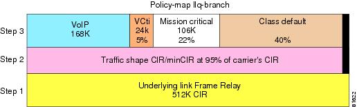
For illustration purposes, assume a 512-Kbps CIR Frame Relay PVC is provisioned at this site. Up to three concurrent voice calls are active—three at 56 Kbps per call or 168 Kbps for voice bearer. Voice Control is allocated 5 percent of the underlying bandwidth and Mission Critical 22 percent.
To avoid an increase in latency as the network traffic approaches the carrier's CIR, traffic shape to 95 percent of the carrier's CIR.
Using a 512 Kbps link as an example, review Figure 6-2 as an illustration of how the policy map overlays on the provisioned link.
Figure 6-2 Example Bandwidth Provisioning for 512 Kbps
The link in the example presented in Figure 6-2 is provisioned as follows:
1.
2.
3.
The following is a sample configuration implementing the traffic categories for a 512 Kbps branch:
!hostname vpn9-2600-1!class-map match-all call-setupmatch ip precedence 3class-map match-any mission-criticalmatch ip precedence 2match ip precedence 6class-map match-all voicematch ip precedence 5!!policy-map llq-branchclass call-setupbandwidth percent 5class mission-criticalbandwidth percent 22class voicepriority 168class class-defaultfair-queue!endFor link speeds other than 512 Kbps, modify the kilobits per second value of the voice class's priority parameter. If separating internetwork-control into a separate class, allocate 5 percent initially and monitor for drops in this class and increase as needed. For example:
!class-map match-all mission-criticalmatch ip precedence 2class-map match-all internetwork-controlmatch ip precedence 6!policy-map llq-branchclass call-setupbandwidth percent 5class mission-criticalbandwidth percent 22class internetwork-controlbandwidth percent 5class voicepriority 168class class-defaultfair-queue!This configuration must be applied to the branch router, the WAN aggregation routers and the corresponding service provider's routers if using a Layer-3 service provider.
Please refer to the "Anti-Replay Considerations" section on page 4-16 for an illustration of modifications that can be made to the queue-limit parameter within bandwidth classes to reduce anti-replay drops.
WAN Implementation Considerations
In deploying the V3PN implementation presented in this SRND, the following key discussions are provided:
•
•
•
•
•
•
WAN Aggregation Router Configuration
In this publication, the preferred implementation separates the IPSec/IP GRE head-end routers from the WAN aggregation routers. The following configuration example is for a 512 Kbps link from the WAN aggregation router., in this case a Cisco 75xx series with VIP4-80 and Channelized T3 interfaces. This Distributed Traffic Shaping configuration offloads the traffic shaping function from the Route Switch Processor (RSP) to the VIP. Distributed CEF (dCEF) was also configured.
The following configuration is an illustration of one link/subinterface. There must be hierarchical policy-maps for each different link speed represented. Each branch in this configuration would have its own time slots and subinterfaces.
vpn2-7500-21 GEIP controller (1 GigabitEthernet).3 VIP4-80 RM7000 controllers (4 Serial)(5 Channelized T3).1 Gigabit Ethernet/IEEE 802.3 interface(s)124 Serial network interface(s)5 Channelized T3 port(s)!ip cef distributed!controller T3 2/0/0clock source linecablelength 50t1 1 channel-group 1 timeslots 1-4t1 2 channel-group 1 timeslots 1-4t1 3 channel-group 1 timeslots 1-4t1 4 channel-group 1 timeslots 1-4t1 5 channel-group 1 timeslots 1-4t1 6 channel-group 1 timeslots 1-4t1 7 channel-group 1 timeslots 1-16t1 8 channel-group 1 timeslots 1-2t1 9 channel-group 1 timeslots 1-4t1 10 channel-group 1 timeslots 1-8! Eight timeslots at 64K each = 512Kbps[...]t1 28 channel-group 1 timeslots 1-2!policy-map 512kbclass call-setupbandwidth percent 5class mission-criticalbandwidth percent 22class voicepriority 168class class-defaultfair-queuepolicy-map 512kb-shaperclass class-defaultshape average 480000 1920 0service-policy 512kb!interface Serial2/0/0/10:1description vpn13-2600-4no ip addressencapsulation frame-relayno fair-queue!interface Serial2/0/0/10:1.102 point-to-pointdescription vpn13-2600-4ip address 192.168.214.1 255.255.255.252frame-relay interface-dlci 102class 512kb!map-class frame-relay 512kbno frame-relay adaptive-shapingservice-policy output 512kb-shaperframe-relay fragment 640!endFrame Relay Traffic Shaping and FRF.12 (LFI)
Frame Relay traffic shaping is configured to rate limit the output packets to the carrier's provisioned CIR as opposed to the clock rate of the output interface. In the case of a branch router, the serial interface clock rate (port speed) might be at a T1 line rate, but the CIR would be provisioned at 768 Kbps. At the head-end WAN aggregation router the difference between output interface might be even greater, an individual site's 128 Kbps CIR might connect to the carrier over a HSSI or Channelized T3 interface.
To eliminate the serialization delay for voice packets on low speed links, Link Fragmentation and Interleaving (LFI) should be configured on interfaces less than 1024 Kbps. On Frame Relay encapsulated interfaces, LFI is implemented by FRF.12.
The key Frame Relay considerations are:
•
•
•
•
The following configuration example should be used as a template for the branch router configuration. In this configuration, each branch has one Frame Relay PVC to the service provider. To increase availability (and cost), two PVCs could be configured—one to each head-end WAN aggregation router. Another alternative would be to provision two serial interfaces, one each to separate Frame-relay providers terminated on separate head-end WAN aggregation routers. A sample branch router with a CIR of 512 Kbps follows:
!hostname vpn13-1700-4!interface Serial1/0description Serial1/0bandwidth 512no ip addressencapsulation frame-relaylogging event subif-link-statuslogging event dlci-status-changeload-interval 30frame-relay traffic-shapingframe-relay lmi-type cisco!interface Serial1/0.1 point-to-pointdescription Serial1/0.1bandwidth 512ip address 192.168.224.2 255.255.255.252frame-relay interface-dlci 101class ts-branchcrypto map static-map!map-class frame-relay ts-branchframe-relay cir 486400frame-relay bc 4864frame-relay be 0frame-relay mincir 486400no frame-relay adaptive-shapingservice-policy output llq-branchframe-relay fragment 640!endTable 6-1 summarizes the different parameters available for Frame Relay Traffic Shaping.
Table 6-2 illustrates parameter values that can be used in the above configuration for the link speeds in the Cisco Enterprise Solutions Engineering lab test.
Frame Relay adaptive shaping is targeted for a configuration where the CIR value equates to the port speed and the MINCIR value is the carrier's CIR value. This configuration allows the network to burst to port speed when no congestion exists in the carrier's network but to traffic shape to CIR during periods of congestion. While this might be advantageous for data only environments, it is not recommended for converged voice and data networks, so it is disabled.
The router's CIR value is shown as 95 percent of the carrier's CIR value. This is to eliminate the possibility of sending data at or above CIR from the switches perspective. The 95 percent is a conservative approach, to prevent over-subscription if the router and frame switch account for Layer-2 overhead differently.
Frame Relay Traffic Shaping involves a concept of "metered bursting", where during an interval of time some number of bits can be sent (or burst) into the Frame Relay carrier's network. The numbers of bits are specified as the committed burst (Bc) and this number of bits is divided by the CIR, or average rate, to derive an interval of time. Interval = Bc/CIR. The Cisco default Frame Relay shaping parameters are Bc is 1/8 of CIR. This default value is 125ms. This value is optimized for data traffic, but introduces delay for voice packets. Simply stated, it is possible the committed burst number of bits transmitted will be exhausted in the first 5 msec of the interval, and thus the algorithm will wait 120 msec before transmitting a subsequent burst.
To optimize the Frame Relay Traffic Shaping parameters—average rate, Bc, and excess burst (Be) for voice—the interval size is reduced. A smaller interval size equates to more intervals per second. An interval size optimal for voice would be in the 10-to-20 msec range or a Bc value of 1-to-2 percent of CIR.
There is, however, a negative effect of this optimization for voice. By decreasing the Bc value, Frame Relay Traffic Shaping becomes engaged or active more aggressively. This in turn provides congestion feedback to the CBWFQ service policy and it might drop or delay packets before the average rate approaches the CIR. This in turn can delay data packets and trigger anti-replay drops. This symptom was exhibited when a show interface, using a 30-second load interval, reports 50-to-60 percent utilization.
The Frame Relay Bc value reduces the interval from the default of 125 msec to 10 msec. Normally Bc is 1/8 of the CIR value which equates to 125 msec. A Bc value of 1 percent the CIR configures an interval of 10 msec for all line rates. For example:
vpn18-2600-2#show traffic-shape s0/0.100Interface Se0/0.100Access Target Byte Sustain Excess Interval Increment AdaptVC List Rate Limit bits/int bits/int (ms) (bytes) Active100 486400 608 4864 0 10 608 -The nature of traffic shaping is to delay, or buffer packets, so the sending rate equates to the credit of bytes per interval. If the Interval is left at the default value of 125 msec, bursts of data traffic that exceed the credit cause the traffic shaping algorithm to wait for that interval to expire before attempting to transmit subsequent packets (which could be voice packets). Decreasing Bc to 10 msec is an accommodation to maintain voice packets within their delay budget.
The definition of MINCIR is the minimum amount of data to be sent during congestion. Congestion is determined by receipt of BECN or ForeSight backward congestion notification messages. This adaptive shaping behavior was disabled in the configuration, so the net result of this configuration parameter is to satisfy CBWFQ's calculation of its bandwidth (in kilobits per second) when classes are allocated using percentages.
For example, if using the following policy map, CBWFQ uses the MINCIR value, frame-relay mincir 486400 to calculate the bandwidth in kilobits per second as illustrated in the subsequent show policy map example output:
policy-map llq-branchclass call-setupbandwidth percent 5class mission-criticalbandwidth percent 22class voicepriority percent 33class class-defaultfair-queueFrom the following display, note that Cisco IOS software has calculated bandwidth for the call-setup class as 24 Kbps as 5 percent of the MINCIR value of 486400.
vpn18-2600-2#show policy-map interface s0/0.100Serial0/0.100: DLCI 100 -Service-policy output: llq-branchClass-map: call-setup (match-all)0 packets, 0 bytes30 second offered rate 0 bps, drop rate 0 bpsMatch: ip precedence 3Weighted Fair QueueingOutput Queue: Conversation 41Bandwidth 5 (%)Bandwidth 24 (kbps) Max Threshold 64 (packets)(pkts matched/bytes matched) 0/0(depth/total drops/no-buffer drops) 0/0/0Attach Service Policy to Frame Relay Map Class
For branch routers after completing configuration of the QoS Service-policy verify it is attached to the Frame Relay map-class.
!map-class frame-relay ts-branchframe-relay cir 486400frame-relay bc 4864frame-relay be 0frame-relay mincir 486400no frame-relay adaptive-shapingservice-policy output llq-branchframe-relay fragment 640!endFor a head-end WAN aggregation router using a VIP and Distributed Traffic Shaping (DTS), verify the shaper is attached to the Frame Relay map-class.
!map-class frame-relay 512kbno frame-relay adaptive-shapingservice-policy output 512kb-shaperframe-relay fragment 640!endApply Traffic Shaping to the Output Interface
For branch routers enable frame-relay traffic-shaping to the physical interface and attach the Frame Relay map-class to all the subinterface DLCIs:
hostname vpn13-1700-4!interface Serial1/0encapsulation frame-relayframe-relay traffic-shaping!interface Serial1/0.1 point-to-pointip address 192.168.224.2 255.255.255.252frame-relay interface-dlci 101class ts-branchendThe 7500 VIP configuration with Distributed Traffic Shaping at the head-end WAN aggregation router is configured similarly, and is shown below. Note that frame-relay traffic-shaping is not configured on the physical interface.
!hostname vpn2-7500-2!interface Serial2/0/0/20:1description vpn13-1700-4no ip addressencapsulation frame-relayno fair-queue!interface Serial2/0/0/20:1.102 point-to-pointdescription vpn13-1700-4ip address 192.168.224.1 255.255.255.252frame-relay interface-dlci 102class 512kb!endApplying Service Policy to HDLC Encapsulated T1 Interfaces
For implementations with T1 interfaces and HDLC encapsulation the following configuration would be used. The voice class is configured for 504 Kbps, which accommodates nine G.729 calls at 56 Kbps per call. The service policy is simply applied to the main interface. The clock rate of the interface provides congestion feedback- no shaping is required in this configuration. No Layer-2 fragmentation (LFI/FRF.12) is required at T1 line rates.
!hostname vpn11-2600-4!policy-map 1536kbclass call-setupbandwidth percent 5class mission-criticalbandwidth percent 22class voicepriority 504class class-defaultfair-queue!interface Serial0/0bandwidth 1536ip address 192.168.154.2 255.255.255.252service-policy output 1536kbcrypto map static-map!endFor the 7500 WAN aggregation router servicing this branch site, the following configuration was used during testing. The policy map is the same as the above branch router configuration.
!hostname vpn2-7500-1!controller T3 2/0/0clock source linecablelength 50[...]t1 10 channel-group 1 timeslots 1-24[...]!interface Serial2/0/0/10:1description vpn11-2600-4ip address 192.168.154.1 255.255.255.252service-policy output 1536kb!Combined WAN and IPSec/IP GRE Router Configuration—Cisco 7200 HDLC/HSSI
The following configuration example applies to a Cisco 7200VXR router that is functioning as a WAN attached head-end router with a HSSI interface and HDLC encapsulation. This router is also configured as the IPSec/IP GRE head-end router with a tunnel interface and a crypto map entry for each remote peer. The voice class priority value would be calculated by multiplying the maximum total number of concurrent calls expected to the remote routers times the bandwidth per call. The mission-critical and call-setup classes are specified in percentages.
Note
!hostname vpn3-7200-1!boot system flash disk0:c7200-ik2s-mz.121-9.E.bin!ip cef!class-map match-all call-setupmatch ip precedence 3class-map match-any mission-criticalmatch ip precedence 2match ip precedence 6class-map match-all voicematch ip precedence 5!policy-map 17408kbclass mission-criticalbandwidth percent 22class voicepriority 5544class call-setupbandwidth percent 5class class-defaultfair-queue!crypto map static-map local-address Hssi3/0crypto map static-map 1 ipsec-isakmpset peer 192.168.1.2set transform-set vpn-testmatch address vpn-static1crypto map static-map 2 ipsec-isakmpset peer 192.168.2.2set transform-set vpn-testmatch address vpn-static2!
Note
!interface Tunnel1description vpn6-2600-1ip address 10.62.1.193 255.255.255.252ip summary-address eigrp 1 10.0.0.0 255.0.0.0 5load-interval 30tunnel source 192.168.251.1tunnel destination 192.168.1.2crypto map static-map!
Note
!interface Hssi3/0description Hssi3/0bandwidth 17408ip address 192.168.251.1 255.255.255.0load-interval 30service-policy output 17408kbhssi internal-clockserial restart-delay 0crypto map static-map!ip access-list extended vpn-static1permit gre host 192.168.251.1 host 192.168.1.2!
Note
IKE and IPSec Configuration
This section addressing configuration of Internet Key Exchange (IKE) and IPSec. These topics are addressed in a series of sections:
•
•
•
•
•
The following sample configurations illustrate the parameters used for the Internet Security Association and Key Management Protocol (ISAKMP) and IPSec security policy.
IKE is a hybrid protocol which implements the Oakley key exchange and Skeme key exchange inside the ISAKMP framework. ISAKMP, Oakley, and Skeme are security protocols implemented by IKE.
Security Associations (SA) are required by both IPSec and IKE. IKE negotiates and establishes its own SA and typically IPSec's SAs are created by IKE.
The IPSec security association lifetimes were the default values of 4608000 kilobytes/3600 seconds. The IKE lifetime was the default value of 24 hours, or 86,400 seconds.
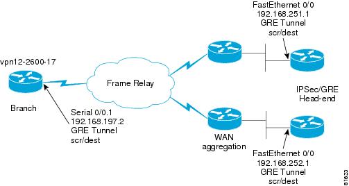
Figure 6-3 illustrates the router addresses and interfaces for the following configuration examples.
Figure 6-3 IKE and IPSec Sample Topology
Configure ISAKMP Policy and Pre-shared Keys
The ISAKMP policy is configured to use group 2 (1024-bit Diffie-Hellman group.) Diffie-Hellman is a public-key protocol to establish session keys, a shared secret, over an unsecured path. Group 1, 768-bit Diffie-Hellman is also supported.
Pre-shared keys were used in lab testing. Pre-shared keys are commonly implemented, estimated at more than 75 percent of implementations—but present scalability challenges.
The IP addresses on the crypto isakmp key statements are the same addresses as configured subsequently as the set peer IP addresses in this router's crypto map. This statement also matches the head-end router's crypto map map-name local-address interface-id statement. There are two keys defined, one for each IPSec/IP GRE head-end router.
This is the branch router's ISAKMP policy and pre-shared key configuration.
!hostname vpn12-2600-17!crypto isakmp policy 1encr 3desauthentication pre-sharegroup 2crypto isakmp key bigsecret address 192.168.252.1crypto isakmp key bigsecret address 192.168.251.1!endThis is a sample from one of the two head-end IPSec/IP GRE routers, in this case the router with the IP address of 192.168.252.1. Each head-end router has a key for each remote peer router's crypto map map-name local-address interface-id configuration command.
!hostname vpn3-7200-2!crypto isakmp policy 1encr 3desauthentication pre-sharegroup 2crypto isakmp key bigsecret address 192.168.1.2crypto isakmp key bigsecret address 192.168.2.2crypto isakmp key bigsecret address 192.168.3.2...crypto isakmp key bigsecret address 192.168.197.2...crypto isakmp key bigsecret address 192.168.244.2!endConfigure IPSec Local Address
Use of the crypto map map-name local-address interface-id can reduce overhead and makes administration easier. It allows the network administrator to determine the interface (and therefore the associated IP address) to be used as the router's identify to the remote peers. Use of the local-address can reduce the number of IKE security associations between two peers if they have multiple interfaces with crypto maps applied.
For routers with multiple or redundant interfaces (multiple paths to reach the IKE/IPSec peers) Loopback addresses are a best practice. This is a similar concept to defining Loopback interfaces and referencing the associated IP address in a dlsw local-peer configuration statement, or snmp-server trap-source interface statement.
In the case of the sample configuration, there is only one interface connecting to the WAN cloud, the example shows using the Serial interface for the branch.
!hostname vpn12-2600-17!crypto map static-map local-address Serial0/0.1!The head-end example references the Fast Ethernet interface.
!hostname vpn3-7200-2!crypto map static-map local-address FastEthernet0/0!In this example, only one local-address statement is needed per router.
Configure IPSec Transform-Set
This design guide implements Triple DES (168-bit /112-bit effective) rather than DES (56-bit). Cisco IOS software with strong encryption is subject to United States government export controls. Triple DES can have limited distribution and therefore might not be an option for use by all organization in all geographies. In general, the stronger the encryption the more computationally intensive. The lab testing represents the worst-case scenario.
SHA-1 is the hash algorithm (for authentication) used by both ISAKMP and IPSec. SHA-1 generates 20-byte hashes. The alternative, MD5—which generates 16-byte hashes—is not recommended as it is considered to have weaknesses. Both hash algorithms are truncated to 12 bytes in the ESP packet as described in RFC2104. The receiver computes the entire 20-byte value and compares the first 12 bytes with the value in the ESP packet
The following configuration is used in all branch and head-end routers.
!crypto ipsec transform-set vpn-test esp-3des esp-sha-hmac!It is common to see configurations that include both ah-sha-hmac and esp-sha-hmac. This is a duplication of the hashing or message integrity function and serves to increase the IPSec overhead. It is not recommended for this design.
Configure Crypto Map
The crypto map configuration ties together the IPSec components configured previously in this chapter.
In the following example, the permit gre host entries in the crypto access lists are the GRE tunnel interface's tunnel source and tunnel destination IP addresses. This match address statement defines what packets are being encrypted and authenticated by IPSec. In this design, that is the IP GRE tunnel that encapsulates the voice and data traffic.
The set peer statements reference the remote router's local-address, and the head-end routers reference this remote router's local-address in their crypto maps. There are two crypto map entries—sequence number 10 and 20—and a transmit and receive IPSec Security Association is created to each head-end router. This example is similar for the head-end routers, however, the map is repeated with the sequence number incremented. The head-end routers include a sequenced entry for each remote peer and an access list for each remote peer.
!hostname vpn12-2600-17!crypto map static-map 10 ipsec-isakmpset peer 192.168.252.1set transform-set vpn-testmatch address vpn-static1crypto map static-map 20 ipsec-isakmpset peer 192.168.251.1set transform-set vpn-testmatch address vpn-static2!ip access-list extended vpn-static1permit gre host 192.168.197.2 host 192.168.252.1ip access-list extended vpn-static2permit gre host 192.168.197.2 host 192.168.251.1!endSince IP GRE tunnels are encrypted and EIGRP is configured for the tunnel interfaces, the EIGRP hello packets force IKE to continually build new IPSec SAs to transmit these hellos—even if no voice or user data traffic is being transmitted. By default, new IPSec SAs are created once per 3600 seconds (one per hour). Thus the IPSec tunnels are always up and available.
Apply Crypto Map to Interfaces
The crypto map configuration command must be applied to both the IP GRE tunnel interface and to the physical interface. For example:
!hostname vpn12-2600-17!interface Tunnel0ip address 10.63.37.194 255.255.255.252tunnel source 192.168.197.2tunnel destination 192.168.252.1crypto map static-map!! Note, Tunnel 1 not shown!interface Serial0/0.1 point-to-pointip address 192.168.197.2 255.255.255.252frame-relay interface-dlci 101class ts-branchcrypto map static-map!Configuring QoS Pre-Classify
When configuring an IPSec encrypted IP GRE tunnel enable qos pre-classify on both the Tunnel interface and crypto map. QoS Pre-Classify is not enabled by default in the releases tested.
!class-map match-all call-setupmatch ip precedence 3class-map match-all mission-criticalmatch ip precedence 2class-map match-all voicematch ip precedence 5!crypto map static-map 10 ipsec-isakmpset peer 192.168.251.1set transform-set vpn-testmatch address vpn-static1qos pre-classifycrypto map static-map 20 ipsec-isakmpset peer 192.168.252.1set transform-set vpn-testmatch address vpn-static2qos pre-classify!interface Tunnel0description Tunnel0ip address 10.62.139.194 255.255.255.252qos pre-classifytunnel source 192.168.91.2tunnel destination 192.168.251.1crypto map static-map!interface Tunnel1description Tunnel1ip address 10.62.139.198 255.255.255.252qos pre-classifydelay 60000tunnel source 192.168.91.2tunnel destination 192.168.252.1crypto map static-map!end
Note
Implementation and Configuration Checklist
This implementation and configuration checklist was compiled to help organize a successful implementation. Unless otherwise noted, these implementation steps must be similarly configured on both branch and head-end routers.
Table 6-3 Summary of Implementation Tasks
Configure IP GRE tunnel interfaces.
Apply EIGRP manual summarization, ip summary-address to IP GRE tunnel interfaces.
Modify EIGRP hold-time if necessary.
Increase delay value for backup IP GRE tunnel interface.
Verify IP GRE tunnel interfaces are up/up and EIGRP neighbors are established.
"Verifying Tunnel Interfaces and EIGRP Neighbors" section on page 7-3
Verify campus switches/workstations/application /IP Phones are setting ToS byte accordingly.
Configure campus edge routers to map ToS to CoS—if applicable
Configure class-maps eg, voice, call-setup, mission-critical
Configure policy-map for WAN edge routers to allocate bandwidth for LLQ and percent classes.
Configure Frame Relay map-class with traffic shaping, and appropriate LFI per link speed.
Apply service-policy to Frame Relay map-class.
Apply Frame Relay traffic-shaping to main interface, apply FRTS map-class to subinterface.
Apply Service Policy to T1 interfaces.
"Applying Service Policy to HDLC Encapsulated T1 Interfaces" section
Configure isakmp policy and pre-shared keys.
Configure ipsec local-address.
Configure ipsec transform-set.
Configure crypto map.
Apply crypto map to Interfaces.
Apply qos pre-classify.
Display IKE and IPSec configuration.
Verify encrypting routers are not Layer-3 fragmenting packets.