Downloads |
Table Of Contents
Verification and Troubleshooting
Verifying Tunnel Interfaces and EIGRP Neighbors
How EIGRP calculates RTO values for Tunnel Interfaces
Using NetFlow to Verify Layer-3 Packet Sizes
Using NetFlow to Verify ToS Values
Sample Show Commands for IPSec
Clearing IPSec and IKE Security Associations
Verification and Troubleshooting
This chapter provides tips to assist in verification and troubleshooting the implementation. Specific troubleshooting discussions address the following:
•
Verifying Tunnel Interfaces and EIGRP Neighbors
•
•
•
•
•
Packet Fragmentation
IPSec and IP GRE headers increase the size of the original packet. Chapter 4, "Planning and Design,"illustrates how a 60-byte G.729 voice packet expands to 136 bytes after addition of the additional headers and trailer. While these relatively small voice packets would not exceed an interface's MTU, data packets at or near MTU size could require fragmentation by the initial or intermediate routers.
Packet fragmentation should be avoided as it decreases router performance, both on the fragmenting router and by the end station. Since encryption is being done with IPSec routers, the end station could be the decrypting router. Fragmentation is performed after encryption and before decrypting; the decrypting router must process switch the packet since it must receive and re-assemble all fragments before decryption.
Fragmentation should be avoided by using either path MTU discovery or manually setting the MTU of the workstations to 1400 bytes. Cisco's VPN Client installation provides a utility that changes the workstation's MTU. From the Window's task bar, select Start, Search, for Files or Folders and search for SetMTU.exe. Execute this program, set the MTU to 1400 bytes and reboot.
To eliminate DLSw induced fragmentation consider defining a MAXDATA value which is smaller than the DLSw, IPsec and GRE overhead. The MAXDATA value is defined under the PU2.0 definition for the switched major node. This value indicates the maximum number of bytes a PU 2.0 device can send/receive. The value specified includes SNA overhead. For example:
MAXDATA=1033,
The default value (line 382) for a Cisco 3174 configuration is 521, a value of 265 is also commonly used.
To set the MTU on a Macintosh with OS X with the terminal program—it requires sudo or root access. Sudo access can be enabled through the NetInfo Manager application located under Applications -> Utilities. Users must go to the Domain pull down menu and under Security select Enable Root Account.
Step 1
Step 2
Note
To display if the encrypting router is fragmenting packets, issue the following command several times while the network is in use:
sh ip traffic | include fragmented4003204 fragmented, 0 couldn't fragmentIf the fragmented counter is increasing, fragmentation is occurring. Refer to the "Using NetFlow to Verify Layer-3 Packet Sizes" section for information about how to use NetFlow to verify packet sizes. Enable NetFlow switching on the interface shared with the workstations to determine the size of the packets prior to encryption.
Fragmentation does not degrade performance of intermediate routers not involved in the fragmentation or re-assembly process. Fragmented packets maintain the ToS byte of the original packet and intermediate router's QoS policy is not affected.
Displaying Anti-Replay Drops
The procedure for displaying packets dropped due to the anti-replay logic differs depending if a hardware crypto accelerator is used or if encryption/decryption is done by software. Since hardware crypto accelerators are recommended for voice, those display examples are presented in this section. With hardware crypto accelerators, the sequence failures are checked and reported by the card, and are not IPSec Security Association (SA) specific, as is the case with software. The counters are an accumulation for all IPSec peers for this router:
For the Cisco 1700, Cisco 2600, Cisco 3600, and Cisco 3700 platforms the command is:
vpn13-1700-4#show crypto engine accelerator statistic | include esp_seq_failesp_prot_absent:0 esp_seq_fail: 0 esp_spi_failure: 0For Cisco 7100 and Cisco 7200 platforms the commands are:
vpn3-7200-1#show pas isa int | include esp_seq_failesp_seq_failure: 249088 esp_spi_failure: 0vpn3-7200-1#show pas vam int | include pkt_replay_errrng_st_fail : 0 pkt_replay_err : 0The counters are accumulated since the hardware crypto accelerator was last initialized or manually cleared with the clear crypto engine accelerator counter command.
Verifying Tunnel Interfaces and EIGRP Neighbors
Before attempting to configure IPSec and encrypt voice packets on the network, verify all the configured interfaces are in UP/UP state:
vpn13-1700-4#show interface | include is upFastEthernet0/0 is up, line protocol is upSerial1/0 is up, line protocol is upSerial1/0.1 is up, line protocol is upLoopback0 is up, line protocol is upTunnel0 is up, line protocol is upTunnel1 is up, line protocol is upVerify that the IPSec/IP GRE head-end routers are neighbors over the tunnel interfaces. This display is from a branch router.
vpn13-1700-4#show ip eigrp neighborsIP-EIGRP neighbors for process 1H Address Interface Hold Uptime SRTT RTO Q Seq Type(sec) (ms) Cnt Num1 10.63.88.193 Tu0 13 1w5d 47 5000 0 2083490 10.63.88.197 Tu1 13 1w5d 46 5000 0 302665For the same branch router, look at the routing table:
vpn13-1700-4#show ip routeCodes: C - connected, S - static, I - IGRP, R - RIP, M - mobile, B - BGPD - EIGRP, EX - EIGRP external, O - OSPF, IA - OSPF inter areaN1 - OSPF NSSA external type 1, N2 - OSPF NSSA external type 2E1 - OSPF external type 1, E2 - OSPF external type 2, E - EGPi - IS-IS, L1 - IS-IS level-1, L2 - IS-IS level-2, ia - IS-IS inter area* - candidate default, U - per-user static route, o - ODRP - periodic downloaded static routeGateway of last resort is 192.168.224.1 to network 0.0.0.0192.168.224.0/30 is subnetted, 1 subnetsC 192.168.224.0 is directly connected, Serial1/0.110.0.0.0/8 is variably subnetted, 7 subnets, 5 masksD 10.0.0.0/8 [90/297246976] via 10.63.88.193, 1w5d, Tunnel0D 10.63.88.0/24 is a summary, 1w5d, Null0C 10.63.88.0/25 is directly connected, FastEthernet0/0C 10.63.88.254/32 is directly connected, Loopback0C 10.63.88.196/30 is directly connected, Tunnel1C 10.63.88.192/30 is directly connected, Tunnel0S* 0.0.0.0/0 [1/0] via 192.168.224.1Note from the above display, network 10.0.0.0/8 was learned from the primary tunnel, Tunnel0. Only the route from the primary tunnel is inserted into the routing table, since in the configuration the interface delay for Tunnel1 was increased, making it an alternate or backup path. Also, note the summary route for 10.63.88.0/24 to the Null0 interface. This is the result of the manual summarization statement on the tunnel interfaces. In this example, only one EIGRP route is being learned through the Tunnel interfaces and only one route is being advertised to each IPSec/IP GRE head-end router.
How EIGRP calculates RTO values for Tunnel Interfaces
This design illustrates the use of EIGRP and GRE Tunnel interfaces. The default bandwidth for a Tunnel interface in Cisco IOS software is 9 Kbps. EIGRP calculates for each neighbor a Retransmission timeout (RTO) value in milliseconds. The RTO value is the amount of time Cisco IOS software waits before a retransmit of a reliable packet (EIGRP an update, query, reply) to its neighbor if an acknowledgement is not received.
The RTO value is computed by calculating:
•
•
Select the higher value of these two calculations. If either computed value is greater than 5,000 milliseconds, the RTO value is set to 5,000 milliseconds, or 5 seconds.
The pacing timer for an interface is calculated from the bandwidth value of the interface. The lower the bandwidth value, the higher the computed pacing timer. The pacing timer is the means to throttle EIGRP's utilization of an interface for routing protocol traffic. By default EIGRP uses up to 50 percent of the bandwidth available. This value can be changed by invoking the ip bandwidth-percent eigrp configuration command.
As an illustration, with the default tunnel bandwidth value of 9 Kbps, the RTO calculation would be 2702 * 6 = 16,212 which is greater than 5,000, so the value of 5,000 is used for the RTO.
vpn-jk-2600-25#show interfaces tunnel 0 | include BWMTU 1514 bytes, BW 9 Kbit, DLY 500000 usec,vpn-jk-2600-25#show ip eigrp interfacesIP-EIGRP interfaces for process 45Xmit Queue Mean Pacing Time Multicast PendingInterface Peers Un/Reliable SRTT Un/Reliable Flow Timer RoutesFa0/1 0 0/0 0 0/10 0 0Tu0 1 0/0 649 71/2702 5894 0vpn-jk-2600-25#show ip eigrp neighbors detailIP-EIGRP neighbors for process 45H Address Interface Hold Uptime SRTT RTO Q Seq Tye(sec) (ms) Cnt Num0 10.248.0.2 Tu0 13 05:05:26 649 5000 0 2Version 12.2/1.2, Retrans: 0, Retries: 0Looking at a tunnel interface which was configured to use a bandwidth value of 56 Kbps, the RTO calculation would be: 434 * 6 = 2,604
vpn-jk-2600-25#show interfaces tunnel 0 | include BWMTU 1514 bytes, BW 56 Kbit, DLY 500000 usec,vpn-jk-2600-25#show ip eigrp interfacesIP-EIGRP interfaces for process 45Xmit Queue Mean Pacing Time Multicast PendingInterface Peers Un/Reliable SRTT Un/Reliable Flow Timer RoutesFa0/1 0 0/0 0 0/10 0 0Tu0 1 0/0 56 11/434 434 0vpn-jk-2600-25#show ip eigrp neighbors detailIP-EIGRP neighbors for process 45H Address Interface Hold Uptime SRTT RTO Q Seq Tye(sec) (ms) Cnt Num0 10.248.0.2 Tu0 14 00:00:18 56 2604 0 4Version 12.2/1.2, Retrans: 1, Retries: 0In either of the above two examples, the SRRT value multiplied by 6 is less than the RTO value multiplied by 6.
A RTO value of 5,000 in itself does not present a problem to the design. The use of manual summarization (and EIGRP stub) in this design minimizes the number of EIGRP updates, queries and replies which must be transmitted between branches and head-end routers. Increasing the bandwidth value for a tunnel interface decreases the pacing time, which allows EIGRP updates, queries and replies to be sent more frequently, but with good summarization the number of these transactions should be minimal.
Using NetFlow to Verify Layer-3 Packet Sizes
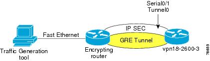
The topology shown in Figure 7-1 is used in this section to illustrate the use of NetFlow to verify Layer-3 packet sizes.
Figure 7-1 Netflow Example Topology
Generate 60-byte (Layer-3) packets with a traffic generator, then use the following command to capture packet information
vpn18-2(TGN:ON,Fa0/1:1/1)#show ipSummary of IP traffic streams on FastEthernet0/1ts# tos len id frag ttl protocol chksm source destination1 UDP A0 60 0000 0000 60 17 6890 10.0.1.2 10.127.0.1Given the following configuration of the router decrypting the traffic, verify the packet sizes by enabling Netflow on the Serial and Tunnel interfaces so the same flow is captured both encrypted and unencrypted:
!hostname vpn18-2600-3!interface Tunnel0ip address 10.0.96.2 255.255.255.0ip route-cache flowtunnel source Loopback0tunnel destination 192.168.2.1crypto map GRE!interface Serial0/1no ip addressencapsulation frame-relayip route-cache flowframe-relay traffic-shaping!interface Serial0/1.100 point-to-pointbandwidth 64ip address 192.168.1.2 255.255.255.252frame-relay interface-dlci 100class ts-branchcrypto map GRE!vpn18-2600-3#sh ip cache verbose flow | begin TOSSrcIf SrcIPaddress DstIf DstIPaddress Pr TOS Flgs PktsPort Msk AS Port Msk AS NextHop B/Pk ActiveTu0 10.0.1.2 Fa0/1 10.127.0.1 11 A0 10 36077D05 /0 0 7D09 /24 0 10.254.0.45 60 72.1Se0/1.100 192.168.1.1 Local 192.168.1.2 32 00 10 2462E74D /30 0 2454 /30 0 0.0.0.0 136 49.1Tu0 192.168.2.1 Null 192.168.1.6 11 00 1017 01F4 /0 0 01F4 /0 0 0.0.0.0 112 140.9In the show ip cache output, the first flow is the UDP packets from the traffic generator, after they were decrypted; the second line shows the IPSec ESP packet (protocol 50) from the Serial interface before it was decrypted; and the last packet is an IKE packet. The increase in packet size (NetFlow reports Layer-3 packet lengths) can be calculated by subtracting the average bytes per packet before and after the IPSec and IP GRE headers. In this case the original packet was 60 bytes, with IPSec (tunnel mode) and IP GRE 136 bytes.
Note
Using NetFlow to Verify ToS Values
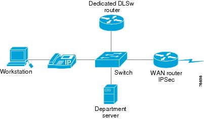
The topology shown below in Figure 7-2 is used to illustrate using NetFlow to verify ToS values from the LAN. There is a dedicated DLSw router advertising its loopback interface via EIGRP to the WAN router that would be the IPSec peer router.
Figure 7-2 Netflow ToS Verification Topology
This is a ToS verification technique which can be done remotely or without the need for a protocol analyzer on the LAN/WAN. This is an alternative to exporting NetFlow to a Collector/Analyzer or other third party collection device. On the WAN router enable NetFlow switching:
!interface FastEthernet0/1ip address 10.254.0.45 255.255.255.0ip route-cache flowendvpn-18-2600-5#show ip cache verbose flow | begin TOSSrcIf SrcIPaddress DstIf DstIPaddress Pr TOS Flgs PktsPort Msk AS Port Msk AS NextHop B/Pk ActiveFa0/1 10.254.0.47 Null 224.0.0.10 58 C0 10 1160000 /0 0 0000 /0 0 0.0.0.0 60 533.1Fa0/1 10.251.0.1 Local 10.254.0.45 06 40 18 20811 /0 0 2B06 /0 0 0.0.0.0 46 0.0From the above show ip cache output, note an EIGRP hello and DLSw flow. These values need to be converted from hex to decimal.
The EIGRP flow is identified by protocol 88 (0x58).
Note
DLSw listens by default on TCP (protocol 0x06) port 2065 (0x0811). In this example, the default IP Precedence value for DLSw was changed from 5 to 2, to match the service policy's "mission-critical" class.
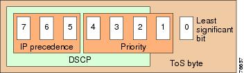
Figure 7-3 ToS Byte Anatomy
Table 7-1 ToS Byte Reference
E0
224
7 Network Control
CS7
111 00000
C0
192
6 Internetwork Control
mission-critical
CS6
110 00000
B8
184
voice
EF
101 11000
A0
160
5 Critical
CS5
101 00000
80
128
4 Flash Override
CS4
100 00000
68
104
call-setup
AF31
011 01000
60
96
3 Flash
CS3
011 00000
40
64
2 Immediate
mission-critical
CS2
010 00000
20
32
1 Priority
CS1
001 00000
00
0
0 Routine
default
000 00000
1 If the TOS hex value converted to decimal falls between the illustrated decimal values, IP Precedence matches on the next lower value. For example, TOS decimal values between 160 and 191 are IP Precedence 5.
The relevant configuration is as follows:
!class-map match-all call-setupmatch ip precedence 3class-map match-any mission-criticalmatch ip precedence 2match ip precedence 6class-map match-all voicematch ip precedence 5!
Sample Show Commands for IPSec
The following commands can be used to verify the implementation values are consistent with these recommendations:
The show crypto map command is used to verify the crypto map configuration. This command facilitates verification of the crypto local and peer IP addresses and the GRE IP addresses match, since in the configuration this information is normally not visible on one page. Also helps to verify that the crypto map is applied to the appropriate output and tunnel interfaces.
vpn13-1700-4#show crypto mapCrypto Map: "static-map" idb: Serial1/0.1 local address: 192.168.224.2Crypto Map "static-map" 10 ipsec-isakmpPeer = 192.168.252.1Extended IP access list vpn-static1access-list vpn-static1 permit gre host 192.168.224.2 host 192.168.252.1Current peer: 192.168.252.1Security association lifetime: 4608000 kilobytes/3600 secondsPFS (Y/N): NTransform sets={vpn-test,}Crypto Map "static-map" 20 ipsec-isakmpPeer = 192.168.251.1Extended IP access list vpn-static2access-list vpn-static2 permit gre host 192.168.224.2 host 192.168.251.1Current peer: 192.168.251.1Security association lifetime: 4608000 kilobytes/3600 secondsPFS (Y/N): NTransform sets={vpn-test,}Interfaces using crypto map static-map:Serial1/0.1Tunnel0Tunnel1With the show crypto isakmp sa command, the state is normally QM_IDLE and there are two IKE security associations, one to each head end router, from the branch perspective. Either the branch or the head-end router can initiate an IKE session, so the destination (dst) and source (src) IP addresses don't have any particular meaning or affinity.
vpn13-1700-4#show crypto isakmp sadst src state conn-id slot192.168.224.2 192.168.252.1 QM_IDLE 1 0192.168.251.1 192.168.224.2 QM_IDLE 2 0The show crypto engine connections active shows both IKE Security associations as well as IPSec. From the previous display, the connection-id of the IKE SAs are 1 and 2, and they are both shown below. From the branch router's perspective, there should normally be four IPSec SAs, since there are two head-end routers and there is a transmit (Encrypt) and receive (Decrypt) SA for each head-end. Note that since the recommended configuration has a primary and secondary IP GRE tunnel, the packet counts are much higher to the primary head-end than to the secondary head-end. Only EIGRP hellos and any other background traffic are traversing the tunnel to the secondary head-end unless the primary fails.
vpn13-1700-4#show crypto engine connections activeID Interface IP-Address State Algorithm Encrypt Decrypt1 Se1/0.1 192.168.224.2 set HMAC_SHA+3DES_56_C 0 02 Tunnel0 10.63.88.194 set HMAC_SHA+3DES_56_C 0 01910 Tunnel0 10.63.88.194 set HMAC_SHA+3DES_56_C 0 5671911 Tunnel0 10.63.88.194 set HMAC_SHA+3DES_56_C 567 01912 Tunnel0 10.63.88.194 set HMAC_SHA+3DES_56_C 0 721913 Tunnel0 10.63.88.194 set HMAC_SHA+3DES_56_C 72 0Use the show crypto isakmp policy to verify the IKE policy and how it differs from the default configuration.
vpn13-1700-4#show crypto isakmp policyProtection suite of priority 1encryption algorithm: Three key triple DEShash algorithm: Secure Hash Standardauthentication method: Pre-Shared KeyDiffie-Hellman group: #2 (1024 bit)lifetime: 86400 seconds, no volume limitDefault protection suiteencryption algorithm: DES - Data Encryption Standard (56 bit keys).hash algorithm: Secure Hash Standardauthentication method: Rivest-Shamir-Adleman SignatureDiffie-Hellman group: #1 (768 bit)lifetime: 86400 seconds, no volume limitUse the show crypto ipsec transform-set to verify of the transform set options as well as tunnel verses transport mode for IPSec.
vpn13-1700-4#show crypto ipsec transform-setTransform set vpn-test: { esp-3des esp-sha-hmac }negotiate = { Tunnel, },Clearing IPSec and IKE Security Associations
When making configuration changes or after a router reload, security associations (SAs) can become `stale', (invalid or out of sync) between two IPSec peers. In some instances this can be the cause for IPSec connectivity failures. This is more common when using IPSec without GRE tunnels and a routing protocol, as the data traffic of the hello packets from the routing protocol forces new SAs to be built to receive and transmit the hellos.
Two clear commands can be used to flush the database and eliminate any legacy negotiations:
clear crypto isakmp
clear crypto sa
Here is an example to illustrate this point and steps through clearing both the IKE and IPSec SAs. Router vpn18-2600-22 is a head-end IPSec/GRE router with one remote router, vpn18-2600-18, which has an IPSec/GRE tunnel to two head-end routers.
From the vpn18-2600-22 device's perspective, there is an IKE and a transmit and receive IPSec SA to the remote router. The remote router is reloaded to simulate a branch failure; note that the EIGRP neighbor goes down and returns.
vpn18-2600-22#show crypto engine connections activeID Interface IP-Address State Algorithm Encrypt Decrypt1 FastEthernet0/1 23.0.1.22 set HMAC_SHA+3DES_56_C 0 02426 Tunnel0 10.96.1.2 set HMAC_SHA+3DES_56_C 0 3122427 Tunnel0 10.96.1.2 set HMAC_SHA+3DES_56_C 312 0vpn18-2600-22#1w4d: %DUAL-5-NBRCHANGE: IP-EIGRP 45: Neighbor 10.96.1.1 (Tunnel0) is down: holdvpn18-2600-22#1w4d: %DUAL-5-NBRCHANGE: IP-EIGRP 45: Neighbor 10.96.1.1 (Tunnel0) is up: new ayvpn18-2600-22#show crypto engine connections activeID Interface IP-Address State Algorithm Encrypt Decrypt1 FastEthernet0/1 23.0.1.22 set HMAC_SHA+3DES_56_C 0 02 FastEthernet0/1 23.0.1.22 set HMAC_SHA+3DES_56_C 0 02428 Tunnel0 10.96.1.2 set HMAC_SHA+3DES_56_C 0 02429 Tunnel0 10.96.1.2 set HMAC_SHA+3DES_56_C 0 02430 Tunnel0 10.96.1.2 set HMAC_SHA+3DES_56_C 0 1542431 Tunnel0 10.96.1.2 set HMAC_SHA+3DES_56_C 154 0
Note
vpn18-2600-18#show crypto engine connections activeID Interface IP-Address State Algorithm Encrypt Decrypt1 <none> <none> set HMAC_SHA+3DES_56_C 0 02 <none> <none> set HMAC_SHA+3DES_56_C 0 0420 Tunnel0 10.96.1.1 set HMAC_SHA+3DES_56_C 0 0421 Tunnel0 10.96.1.1 set HMAC_SHA+3DES_56_C 0 0422 Tunnel0 10.96.1.1 set HMAC_SHA+3DES_56_C 0 187423 Tunnel0 10.96.1.1 set HMAC_SHA+3DES_56_C 185 0424 Tunnel0 10.96.1.1 set HMAC_SHA+3DES_56_C 0 0425 Tunnel0 10.96.1.1 set HMAC_SHA+3DES_56_C 0 0426 Tunnel0 10.96.1.1 set HMAC_SHA+3DES_56_C 0 184427 Tunnel0 10.96.1.1 set HMAC_SHA+3DES_56_C 184 0The branch has two active IPSec SAs to each head-end, Ids 422/423 and 426/427 and two IKE SAs, 1 and 2. Clearing the SAs eliminates the redundant SAs.
vpn18-2600-18#clear crypto savpn18-2600-18#show crypto engine connections activeID Interface IP-Address State Algorithm Encrypt Decrypt1 <none> <none> set HMAC_SHA+3DES_56_C 0 02 <none> <none> set HMAC_SHA+3DES_56_C 0 0420 Tunnel0 10.96.1.1 set HMAC_SHA+3DES_56_C 0 2421 Tunnel0 10.96.1.1 set HMAC_SHA+3DES_56_C 2 0422 Tunnel0 10.96.1.1 set HMAC_SHA+3DES_56_C 0 2423 Tunnel0 10.96.1.1 set HMAC_SHA+3DES_56_C 1 0After the clear command, there are two IKE SAs, and four IPSec SAs, a transmit and receive tunnel to each head-end.
Now, looking at the IKE SAs, they are in a normal state Quick-Mode Idle, clearing them deletes the IKE SAs.
vpn18-2600-18#show crypto isakmp sadst src state conn-id slot23.0.32.22 23.0.218.1 QM_IDLE 2 023.0.32.23 23.0.218.1 QM_IDLE 1 0vpn18-2600-18#clear crypto isakmpvpn18-2600-18#show crypto isakmp sadst src state conn-id slot23.0.32.22 23.0.218.1 MM_NO_STATE 2 0 (deleted)23.0.32.23 23.0.218.1 MM_NO_STATE 1 0 (deleted)vpn18-2600-18#show crypto isakmp sadst src state conn-id slot
Note
vpn18-2600-18#show crypto engine connections actID Interface IP-Address State Algorithm Encrypt Decrypt420 Tunnel0 10.96.1.1 set HMAC_SHA+3DES_56_C 0 63421 Tunnel0 10.96.1.1 set HMAC_SHA+3DES_56_C 62 0422 Tunnel0 10.96.1.1 set HMAC_SHA+3DES_56_C 0 62423 Tunnel0 10.96.1.1 set HMAC_SHA+3DES_56_C 61 0To force IKE SAs establishment, clear the IPSec SAs (IKE SAs need to be build to establish new IPSec SAs).
vpn18-2600-18#clear crypto savpn18-2600-18#show crypto engine connections actID Interface IP-Address State Algorithm Encrypt Decrypt1 <none> <none> set HMAC_SHA+3DES_56_C 0 02 <none> <none> set HMAC_SHA+3DES_56_C 0 0420 Tunnel0 10.96.1.1 set HMAC_SHA+3DES_56_C 0 11421 Tunnel0 10.96.1.1 set HMAC_SHA+3DES_56_C 12 0422 Tunnel0 10.96.1.1 set HMAC_SHA+3DES_56_C 0 11423 Tunnel0 10.96.1.1 set HMAC_SHA+3DES_56_C 11 0vpn18-2600-18#show crypto isakmp sadst src state conn-id slot23.0.32.22 23.0.218.1 QM_IDLE 1 023.0.32.23 23.0.218.1 QM_IDLE 2 0From the above display, the router is functioning normally, and the expected number of security associations are seen in the display.
Sample Show Commands for QoS
Use the show policy-map interface to verify the offered rate of traffic isn't greater than the allocated bandwidth for the voice, call-setup and mission-critical classes, as drops in these classes impact voice quality, call setup and the important data applications.
If there are drops in the voice class, either the call admission control configuration is not consistent with the amount of bandwidth allocated for voice calls, or there could be a minor amount of jitter in the call that is causing the voice packets to arrive slightly over the rate calculated per call. If the call admission control issue was verified, the CODEC type isn't G.711 when it was planned to be G.729, and there is a minor amount of voice being dropped, then increase the value of the priority queue until the drops stop.
If there are drops in the IP Precedence 6 class within mission-critical, expect to experience EIGRP neighbors drop. The service policy should be tuned to prevent EIGRP packets from being dropped, as EIGRP packet drops cause instability in the network.
In the release of code tested, the offered rate (in bits per second) does not include GRE and IPSec header overhead; however, the packets per second rates should report accurate packet rates.
vpn13-1700-4#show policy-map interface serial 1/0.1Serial1/0.1: DLCI 101 -Service-policy output: llq-branchClass-map: call-setup (match-all)0 packets, 0 bytes30 second offered rate 0 bps, drop rate 0 bpsMatch: ip precedence 3Weighted Fair QueueingOutput Queue: Conversation 41Bandwidth 5 (%)Bandwidth 24 (kbps) Max Threshold 64 (packets)(pkts matched/bytes matched) 0/0(depth/total drops/no-buffer drops) 0/0/0Class-map: mission-critical (match-any)2992 packets, 392844 bytes30 second offered rate 2000 bps, drop rate 0 bpsMatch: ip precedence 20 packets, 0 bytes30 second rate 0 bpsMatch: ip precedence 62992 packets, 392844 bytes30 second rate 2000 bpsWeighted Fair QueueingOutput Queue: Conversation 42Bandwidth 22 (%)Bandwidth 106 (kbps) Max Threshold 64 (packets)(pkts matched/bytes matched) 2994/393695(depth/total drops/no-buffer drops) 0/0/0Class-map: voice (match-all)0 packets, 0 bytes30 second offered rate 0 bps, drop rate 0 bpsMatch: ip precedence 5Weighted Fair QueueingStrict PriorityOutput Queue: Conversation 40Bandwidth 168 (kbps) Burst 4200 (Bytes)(pkts matched/bytes matched) 0/0(total drops/bytes drops) 0/0Class-map: class-default (match-any)26601 packets, 10030161 bytes30 second offered rate 0 bps, drop rate 0 bpsMatch: anyWeighted Fair QueueingFlow Based Fair QueueingMaximum Number of Hashed Queues 32(total queued/total drops/no-buffer drops) 0/0/0Use the show frame-relay fragment command to verify the fragment size in bytes, and the number of packets that require fragmentation.
vpn13-1700-4#show frame-relay fragmentinterface dlci frag-type frag-size in-frag out-frag dropped-fragSerial1/0.1 101 end-to-end 640 154 154 0