-
Massively Scalable Data Center (MSDC) Design and Implementation Guide
-
MSDC Design Architecture Preface
-
MSDC Reference Design Architecture
-
MSDC Solution Details and Testing Summary
-
Server and Network Specifications
-
Buffer Monitoring Code and Configuration Files
-
F2/Clipper Linecard Architecture
-
Competitive Landscape
-
Incast Utility Scripts, IXIA Config
-
Bandwidth Utilization Noise Floor Traffic Generation
-
 Feedback
Table Of Contents
F2/Clipper Linecard Architecture
Life of a Packet in F2—Data Plane
Introduction to Arbitration Process
F2/Clipper Linecard Architecture
Since the F2 linecard is an important aspect of building high-density, line-rate, Spines in the MSDC space, further discussion is warranted. This section explores unicast forwarding [only] in greater detail within the F2 linecard.
F2 topics which are beyond the scope of this document include:
1.
FIB lookup success/failure
2.
3.
Traffic sources and bursts are extremely random and non-deterministic for a typical distributed application in MSDCs. As an example, consider a Hadoop workload. Map and reduce nodes are determined during runtime by the job tracker based on data block location and server memory/cpu utilization. As a workload enters the shuffle phase, network "hotspots" can occur on any physical link(s) across the L3 fabric. Since congestion control is closely aligned with egress interface buffers, deep buffers are required on all physical interfaces. Insufficient buffer size can cause application degradation1 . But on the other hand, buffers that are too large can hinder predictability due to increased latencies, and latency variations. As such, careful examination of how buffering works on key MSDC building blocks is essential.
F2 Architecture Overview
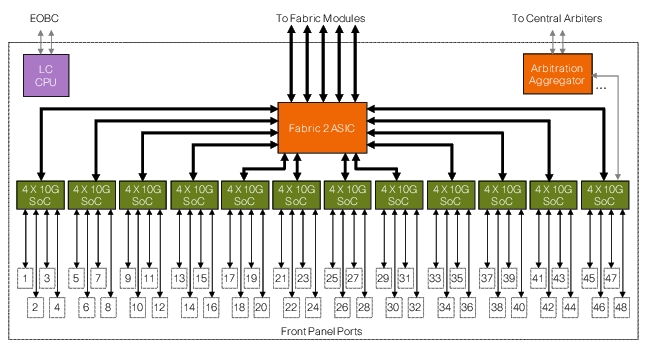
The F2 line module consists of 12 dedicated System on Chip (SoC) ASICs, each ASIC supports 4 line rate 10GE interfaces and has the following characteristics (Figure C-1):
•
•
•
•
Other features include3 :
•
•
•
•
Figure C-1 F2 Architecture Overview
With regard to data forwarding, each SoC has two dedicated connections:
1.
2.
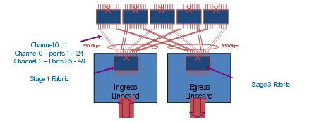
Similar to previous generation M or F series modules, traffic destined between F2 line cards are sent across the crossbar (xbar)-fabric module (2nd stage fabric). Each F2 I/O module has up to 10x 55G connections towards the 2nd stage Fabric (Figure C-2). Five fabric connections are referred to as channel 0 connections, the remaining five are classified as channel 1 connections. Second stage fabric is either a 1st gen FAB1 or 2nd gen FAB2 module. While F2 is compatible with both, FAB2 cards are required for line-rate deployment scenarios; FAB2's are used in the SDU MSDC test topology. Except for migration purposes Cisco does not recommend deployments with a mixture of FAB1 and FAB2 modules.
F2 requires deploying an F2-only VDC, thus interoperability of F2 with M or F1 cards, in the same VDC, is not supported. If an F2 module is inserted in a chassis with M modules, all interfaces will be in unallocated state until placed in a dedicated F2-only VDC.
Figure C-2 Linecard to Fabric Connections
Arbitration is required for all unicast flows. The purpose of arbitration is to avoid Head-of-line Blocking (HOLB)4 within the switch fabric and to provide Quality of Service (QoS) differentiation based on traffic class. Arbitration ASICs on linecards perform arbitration tasks among local SoC requesters and act as a proxy to request credit on behalf of all SoCs on the same linecard, with the central arbiter on the Supervisor (SUP). Unicast packets are only transmitted to fabric when credits are available. Broadcast, unicast flood, and multicast traffic do not require arbitration.
Life of a Packet in F2—Data Plane
At a high-level packet forwarding in F2 follows these four steps:
1.
2.
3.
4.
Packets are stored in the ingress buffer when received from the network. Packet headers are extracted and sent to the decision engine to perform L2/L3 forwarding lookup. Once the forwarding decision is made, packet is rewritten and queued to a virtual output queue based on traffic type and QoS. If a packet is multicast, it is sent directly across the fabric. Before sending across the fabric, unicast packets ingress the linecard and queries the arbitration engine to ensure sufficient egress buffers are available. If there are multiple ingress sources sending traffic to a common egress destination the arbitration engine provides fairness and order-of-transmission. As mentioned earlier, this section only focuses on unicast traffic.
The lookup process returns the following [required] information:
1.
2.
Introduction to Queueing
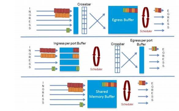
Figure C-3 shows there are three widely supported buffer/queue models in datacenter switches: shared, ingress and egress queuing.
Figure C-3 Three Buffer Models: Ingress, Egress, and Shared
Since this section is examing F2 (and F2 does not employ a shared buffer model), the remaining discussion for this sub-section will discuss Ingress and Egress buffering. See TCP Incast discussion further down in this document for an examination of how N3064s utilize shared buffering.
In egress buffering methods, traffic is pushed through the switch fabric; output scheduling and queuing occurs on the egress interface. Most egress based buffer implementations allocate fixed size buffers to each interface, and consequently the amount of burst interfaces can absorb is limited by the size of the egress buffer.
Unlike egress buffering, ingress buffering architectures absorb congestion on ingress via distributed buffer pools. The amount of buffer available is a function of traffic flow. For example, in a 2:1 Incast scenario, there are 2x input buffers to absorb the burst. As the number of source interfaces increase, the amount of ingress buffers increases accordingly. If we add one additional sender to create a 3:1 Incast scenario, we have 3x input buffers. The simplest way to characterize ingress buffering is: the amount of available buffers equal to number of interfaces sending traffic to a single destination. Traffic bursts which exceed the egress capacity will be dropped on the ingress interface. Ingress queuing in general scales well in an environment with large fan-outs. F2 implementation is based on ingress buffering. Each port is assigned ~1.5MB of ingress buffer.
Queueing in F2 Hardware
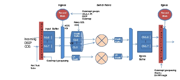
Packet queuing occurs at multiple stages when transmitting across a F2 based system. Figure C-4 shows key queuing points with F2 10G I/O modules.
Figure C-4 Queueing in Hardware
Virtual Lane—separated into ingress (iVL) /egress (oVL). VL enables the ability to support traffic differentiation based CoS or DSCP on a physical link. There are three mechanisms to classify a packet into iVL:
1.
2.
3.
Packet classification for oVL depends on the type of traffic. Default classification is based on received CoS for bridged traffic. For routed traffic, received CoS is rewritten based on DSCP, derived CoS is used for egress queuing.
Flow Control—Flow control is a congestion avoidance mechanism to signal to the remote station to stop sending traffic due to high buffer usage. There are two types of flow control, Priority Flow Control (PFC) / Link Flow Control (LFC). LFC is at the link level and independent of the COS. PFC is based on VL, typically implemented to provide lossless service such as FCOE. PFC / LFC are mutually exclusive. F2 does not support flow control per COS value.
ACoS (Advanced Class of Service)—This is the internal classification and treatment of a packet within the data path of the switch, it is carried end to end as part of the DC3 internal header across the data path. ACOS values are often derived from configured inbound policies during the forwarding lookup process.
CCoS—CCoS is derived from the ACoS. Based on CL (fabric qos level) Switch maintains a static mapping table between the ACoS and CCoS. Combination of VQI:CCoS makes up the VoQ.
Credited / Un-credited Traffic—Credited traffic are unicast traffic that has gone through full arbitration process. Un-credited traffics are those that do not require arbitration. Typically multicast, broadcast and unknown unicast are transmitted as un-credited traffic flows. If an interface has both credited and un-credited traffic, configured DWRR weight determines amount of traffic to send for each type.
VQI and VoQ—A VQI (virtual queue index) is the index or destination port group id over the fabric. A VQI always maps to a port group, representing 10G worth of bandwidth. Each port group consists of multiple interfaces (M1 series 10G shared mode or 12X 1GE) or a single dedicated interface (M1 series running in dedicate mode or F series line cards). Number of QoS levels per VQI varies between hardware: M series supports 4 COS / VQI, while F2 supports 8. The mapping of VQI to CCoS is often referred to as VoQ. A line card can have up to QoS Level * VQI number of VoQs. Specific to the F2 Line card:
1.
2.
3.
In practice, the number of usable VoQ is based on fabric QoS levels. Current implementation in the Nexus 7000 family supports 4 Credit Loop (QoS level), this implies the number of usable VOQ is 4 * 1024 or 4096 VOQs.
LDI—LDI is an index local to the Linecard. An interface is defined by a 6 bit LDI in SUP-1, 7 bit LDI in SUP-2. When communicating with the central arbiter, linecards use LDIs to indicate interface id. On the central arbiter, every LDI maps to a unique VQI. This mapping is based on the received interface of the arbitration message and LDI.
Ingress Logic
Nexus 7000 F2 implementation is based on ingress buffering. In the case of F2 I/O module, the VoQ buffer is the input port buffer. Each SoC has 6MB of buffer which is shared by the 4 front-panel port results in ~1.5MB of ingress buffer per port, represented as 3584 pages of input buffer at 384 bytes per page. 6 MB is equivalent to 1.25 ms buffering. There is also a 1MB skid buffer per SoC, 250KB per interface; this is only used with PFC. Buffer pages are assigned to various input queues depending on the system / port queue configuration. Using the default 2q4t (two input queue and 4 threshold per queue) configuration with 90/10 queue limit, 3195 pages are assigned to queue 0 (90%) and 338 pages are assigned to queue 5 (10%).
Ingress Queuing for Ethernet1/1 [System]-------------------------------------------Trust: TrustedDSCP to Ingress Queue: Disabled-----------------------------------Que# Group Qlimit% IVL CoSMap-----------------------------------0 1 90 0 0-41 0 10 5 5-7Traffic to ingress queue mapping can be based on CoS (default) or DSCP (starting from nxos 6.1.1). Packets are queued to corresponding iVL awaiting lookup results based on the following mapping:
UP 0 - 4 -> IVL 0UP 5 - 7 -> IVL 5iVL buffer utilization can be monitored by attaching to the linecard. Refer to Monitor F2 drop section for details.
Figure C-5 CLI Output
Once lookup results are received from the decision engine, packet headers are rewritten and forwarded to corresponding VoQs for arbitration. ACoS values are used to determine QoS levels across the fabric. There are three lookup tables, 8cl, 4cl, and 4clp - the CL mode determines which table to query. 8cl is used for 8 queue (CL) mode while 4cl and 4clp are for 4 queue mode (p indicates if priority bit set or not).
module-1# show hardware internal qengine inst 0 vq acos_ccos_4clACOS CCOS---- ----0 31 32 23 14 15 06 07 08 - 15 316 - 23 224 - 39 140 - 63 0msdc-spine-r1# show hardware internal qengine asic 0 gb pri-mapping00000000: 03 03 02 01 01 00 00 00 - 03 03 03 03 03 03 03 0300000010: 02 02 02 02 02 02 02 02 - 01 01 01 01 01 01 01 0100000020: 01 01 01 01 01 01 01 01 - 00 00 00 00 00 00 00 0000000030: 00 00 00 00 00 00 00 00 - 00 00 00 00 00 00 00 00msdc-spine-r1#This mapping has to be the same on all I/O modules and SUP across the entire switch. CSCuc07329 details some of the issues that can occur when mismatch occurs.
Once CCoS is determined, packet is queued into the corresponding VoQ (VQI: CCoS) for central arbitration. Current generation SoCs do not allow drops on the VoQ, all congestion related drops can only occur at iVL for unicast traffic. iVL drops show up as indiscards on the physical interface and queue drops under qos queuing policy. Future F2 series I/O modules will support VoQ drops. Before accepting a packet into the VoQ, WRED and tail checks are performed based on instant buffer usage. If the instant buffer usage is greater than the buffer threshold or number of packets in the output queue is higher than packet count threshold, incoming packet are dropped. It is important to highlight that WRED and tail drop applies to droppable VLs only if PFC is enabled. Central arbitration occurs once packets are accepted into the VoQ. Refer to Introduction to Arbitration Process for arbitration details.
Egress Logic
On the egress side, there are additional 755 pages of FIFO buffer for credited and 512 pages for broadcast / multicast traffic. Credited traffic consists of Super frames (packets or Jumbo frames with segments), and buffer space is reserved and managed by the Arbiter. Credited traffic is sent to an egress linecard only when it has been granted buffer space by the central arbiter and can only be destined to one VQI. The egress buffer must be returned to the arbiter once egress interface completes its transfer. If traffic arrives out of order on the egress line card, it is the responsibility of the egress logic to re-order packets before being transmitted out of the output interface.
If an interface has both credited and un-credited traffic, configured DWRR weights determine the amount of traffic to send for each type.
DWRR weight for credited and uncredited traffic:
DWRR weights:Q# Credited Uncredited0 8190 54601 8190 54602 8190 54603 8190 5460Egress QoS policy controls how various classes of traffic are prioritized when being transmitted out of an interface. Default egress queue structure is based on 1p3q4t (one priority queue and 3 normal queues - each queue has 4 drop threshold), CoS 5, 6, 7 are mapped to the priority queue, DWRR is implemented between queue Q1-3. For bridged traffic, received CoS is used for both ingress and egress classification by default. If ingress classification is changed to DSCP, by default egress CoS value for bridged traffic remains unchanged. On the egress side, received CoS will remain for egress queue selection, and DSCP is ignored. An example of this would be a bridged packet marked with CoS 0 / 46 DSCP as it enters the switch, then it will be treated as premium data on the ingress based on DSCP classification. On the egress side, it will continue to be mapped to the default queue due to COS 0. A policy map can be applied at the egress interface if DSCP based queuing on the egress is required. For routed traffic, either CoS or DSCP can be used for ingress queue selection. DSCP is used to rewrite the CoS on the egress interface. Derived CoS will be used for egress queue selection.
WRED is not supported on F2 modules. The following output highlights F2 output queue information.
Flexible Scheduler config:
System Queuing mode: 4QQ 0: VLs (5,6,7) priority Q HI,Q 1: VLs (3,4) DWRR weight 33,Q 2: VLs (2) DWRR weight 33,Q 3: VLs (0,1) DWRR weight 33In a unicast-only environment, no drops occur on the egress for credited traffic. Arbitration processes ensure traffic is only sent over the fabric if egress buffers exist. This is a by-product of ingress based queuing; traffic exceeding egress bandwidth of the egress port will only consume necessary fabric bandwidth, and will be dropped at the ingress. Egress queuing policy on F2 controls how much an egress port receives from ingress ports. If a mixture of priority and best-effort traffic exists, egress policy assigns higher precedence to priority traffic.
Introduction to Arbitration Process
By nature packet switching is uncoordinated and clusters of traffic often contend for the same switching resource. When contention occurs, it becomes impossible to honor service level agreements (SLAs) or guarantee packet forwarding fairness. Thus lossless switching required for consolidated services such as FCoE is not possible. This is the reason arbitration engines are required in datacenter switches. An Arbiter decides the order packets are sent across the switch. In a credited system, a packet is moved from ingress to egress through the switching fabric only if the egress port has sufficient buffering available. All the input ports send requests to the Arbiter. Based on availability of buffers, and other requestors, the Arbiter accepts or denies the request. Packet arbitration ensures fairness in the systems and avoids resource deadlock and provides near-lossless delivery of packets
Arbitration policy and pattern of traffic entering the switch often impact switching performance and throughput per slot. Available products today are generally based on centralized arbiters; it scales well to 100G line-rate. Credit-ID and credit-counter based central arbitration are implemented in the Nexus product family. Credit-ID based arbitration assigns 3 bit grant id (GID) to each buffer page. The input port includes the GID as part of the linecard header when transmitting packets to the egress port. Once a packet is transmitted, egress buffers credit back the tokens (GIDs) to the central arbiter.
Credit recovery is based on timeouts. Credit-counter based arbitration assigns buffer pages with a counter, both central arbiter and linecard maintains the number of outstanding tokens in-flight. Similar to credit-id based arbitration, egress buffer credits back the token to the central arbiter upon transmission. To recover a lost token, the central arbiter issues a CreditQuery messages to the egress linecard, and compares its counter with the corresponding CreditReply response from the line card.
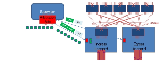
Figure C-6 shows the high level concepts involved in a centralized arbitration system.
Figure C-6 Centralized Arbitration
For unicast packet forwarding, once a lookup decision is made on ingress, packets containing output VQIs and Credit Loops (QoS levels) are sent to the central arbiter seeking permission for transmission across the fabric. If egress buffers are available the central arbiter grants (GNT) the permission to transmit (a GNT message) to the arbitration aggregator on the linecard. The ingress linecard starts transmission across the fabric upon receiving the GNT message. Super frames are used if multiple small packets are destined for the same egress VOQ, performed in the same arbitration cycle. Packets are stored in egress buffers once it reaches the egress linecard. Once it's processed, packets are then sent via egress port logic and a token (GID) is returned to the central arbiter via buffer available (CRD) messages.
As the industry increases demand for 100G, requirements for high density 100G lineorate interfaces will correspondingly increase as well. High density 100G interfaces require substantial increases in slot and system throughput. Increases in capacity requirements are accomplished with distributed flow arbitration. Distributed flow arbitration removes the central arbiter and integrates the buffer/token allocation with the flow status on the ingress / egress linecard. Buffer management is based on flow status - sequence number, and/or TCP window sizes, are used to control the rate of data transmission. When implemented properly flow status alleviates egress congestion and enables dead-lock avoidance at multi-Tbps throughput. Distributed arbitration is a roadmap item and is not required for current throughput demands.
Additional information Specific to F2 implementation
Depending on system configuration F2 works either in Credit-ID or Credit-counter based arbitration. F2 works in Credit-ID based mode in SUP1 based systems, Credit-counter mode in SUP2 based systems. When working in SUP1 based systems, 8 tokens (Credits per {VQI, CL}) are required to sustain 10GE line rate with super framing. The central arbiter keeps track of tokens based on GID and will not issue additional grants to a destination if it has already issued 8 outstanding grants. Additional tokens are only granted once the egress linecard indicates there is a free buffer available (CRD). SUP2 based systems increase the number of outstanding tokens to 256.
Network administrators and operators need to be aware of the following information:
1.
2.
3.
4.
5.
Monitoring Packet Drops
This section presents tools network engineers use to understand various aspects of F2's behavior.
IVL/Pause Frames
Port QoS configuration indicates flow control status:
module-1# show hardware internal mac port 1 qos configurationQOS State for port 1 (Asic 0 Internal port 1)GDTX PAUSE:VL# ENABLE RESUME REFRESH REF_PERIOD QUANTA0 OFF OFF OFF 0x0 0x01 OFF OFF OFF 0x0 0x02 OFF OFF OFF 0x0 0x03 OFF OFF OFF 0x0 0x04 OFF OFF OFF 0x0 0x05 OFF OFF OFF 0x0 0x06 OFF OFF OFF 0x0 0x07 OFF OFF OFF 0x0 0x0LFC ON ON ON 0x1000 0xffffRX PAUSE:VL 0-7 ENABLE: OFF OFF OFF OFF OFF OFF OFF OFF LFC: ONAs discussed previously, the system sends pause frames when buffers run low. The number of pause states entered is viewed from the show hardware command. ID 2125-2130 indicates which UP are in internal pause state due to high buffer usage. UP0 - UP4 maps to iVL0:
module-1# show hardware internal statistics device mac congestion port 1|------------------------------------------------------------------------|| Device:Clipper MAC Role:MAC Mod: 1 || Last cleared @ Wed Sep 12 10:04:03 2012| Device Statistics Category :: CONGESTION|------------------------------------------------------------------------|Instance:0ID Name Value Ports-- ---- ----- -----2125 GD uSecs port is in internal pause tx state 0000000041585643 1 -2126 GD uSecs UP0 is in internal pause tx state 0000000041585643 1 -2127 GD uSecs UP1 is in internal pause tx state 0000000041585643 1 -2128 GD uSecs UP2 is in internal pause tx state 0000000041585643 1 -2129 GD uSecs UP3 is in internal pause tx state 0000000041585643 1 -2130 GD uSecs UP4 is in internal pause tx state 0000000041585643 1 -module-1# show hardware internal mac qos configurationUP 2 IVL:DE 0 UP 0 IVL 0DE 1 UP 0 IVL 0DE 0 UP 1 IVL 0DE 1 UP 1 IVL 0DE 0 UP 2 IVL 0DE 1 UP 2 IVL 0DE 0 UP 3 IVL 0DE 1 UP 3 IVL 0DE 0 UP 4 IVL 0DE 1 UP 4 IVL 0DE 0 UP 5 IVL 5DE 1 UP 5 IVL 5DE 0 UP 6 IVL 5DE 1 UP 6 IVL 5DE 0 UP 7 IVL 5DE 1 UP 7 IVL 5Ingress Buffer
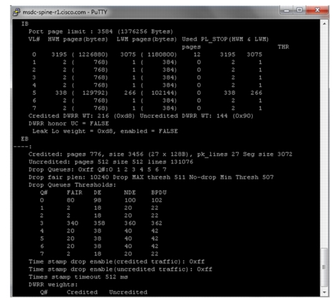
Since F2 is based on the ingress buffering model, visibility into input buffer usage is critical to determine overall performance of a distributed application. When input buffers are consumed (due to the egress endhost is receiving more traffic than it can handle) it is important to proactively identify a set of interfaces which contribute to congestion and re-route workloads to another system that has excess capacity. F2 input buffer usage is viewed by issuing a show hardware internal mac command. This command reports the number of input buffers allocated and used based on iVL:
module-1# show hardware internal mac port 1 qos configurationIBPort page limit : 3584 (1376256 Bytes)VL# HWM pages(bytes) LWM pages(bytes) Used PL_STOP(HWM & LWM)Pages THR0 3195 ( 1226880) 3075 ( 1180800) 21 3195 30751 2 ( 768) 1 ( 384) 0 2 12 2 ( 768) 1 ( 384) 0 2 13 2 ( 768) 1 ( 384) 0 2 14 2 ( 768) 1 ( 384) 0 2 15 338 ( 129792) 266 ( 102144) 0 338 2666 2 ( 768) 1 ( 384) 0 2 1The number of drops per iVL or interface is tracked via input QoS policy; use the show policy-map command to get the total number of ingress drops at ingress queue:
msdc-spine-r1# show policy-map interface ethernet 1/1Global statistics status : enabledEthernet1/1Service-policy (queuing) input: default-4q-8e-in-policyClass-map (queuing): 2q4t-8e-in-q1 (match-any)queue-limit percent 10bandwidth percent 50queue dropped pkts : 0Class-map (queuing): 2q4t-8e-in-q-default (match-any)queue-limit percent 90bandwidth percent 50queue dropped pkts : 342737Alternatively, show interface also displays the number of input drops:
RX230574095573 unicast packets 10261 multicast packets 46 broadcast packets230574092331 input packets 99092487394083 bytes0 jumbo packets 0 storm suppression packets0 runts 0 giants 0 CRC 0 no buffer0 input error 0 short frame 0 overrun 0 underrun 0 ignored0 watchdog 0 bad etype drop 0 bad proto drop 0 if down drop0 input with dribble 342737 input discard0 Rx pauseThe total number of packets received across iVL is tracked via the show hardware internal statistics device mac all port command:
module-1# show hardware internal statistics device mac all port 1 | i PL12329 PL ingress_rx_total (vl0) 0000230219507695 1 -12334 PL ingress_rx_total (vl5) 0000000000010246 1 -12345 PL ingress_rx_bytes (vl0) 0098940369532487 1 -12350 PL ingress_rx_bytes (vl5) 0000000002042488 1 -12369 PL ingress_rx_total_bcast (vl0) 0000000000000046 1 -12382 PL ingress_rx_total_mcast(vl5) 0000000000010246 1 -12385 PL ingress_rx_total_ucast (vl0) 0000230219509065 1 -12409 PL ingress_congestion_drop_nde_vl0 0000000000342737 1 -12441 PL ingress_congestion_drop_bytes_nde_vl0 0000000154973799 1 -The show hardware internal statistics device fabric errors command is used with FAB2 to display the number of times a frame with a bad CRC enters the fabric ASIC.
To display the number of bad frames received by egress engines, use the show hardware internal statistics module-all device qengine errors command.
VOQ Status
In F2's case, VQI index tracks interface LTL index. Both indexes are assigned by the Port manager:
msdc-spine-r1# show system internal ethpm info interface ethernet 1/1Information from GLDB Query:Platform Information:Slot(0), Port(0), Phy(0x2)LTL(0x77), VQI(0x77), LDI(0x1), IOD(0x358)Backplane MAC address in GLDB: 6c:9c:ed:48:c9:28Router MAC address in GLDB: 00:24:98:6c:72:c1Packets requiring central arbitration are queued in respective VoQs awaiting tokens. The number of outstanding frames per VOQ are monitored based on VQI:CCoS:
module-3# show hardware internal qengine voq-statusVQI:CCOS CLP0 CLP1 CLP2 CLP3 CLP4 CLP5 CLP6 CLP7 CLP8 CLP9 CLPA CLPB-------- ----- ----- ----- ----- ----- ----- ----- ----- ----- ----- ----- -----0033:3 0 2 0 0 0 0 0 0 0 0 0 00033:4 0 0 0 0 0 0 0 0 0 0 0 0module-3# show hardware internal qengine inst 0 voq-statusVQI:CCOS BYTE_CNT PKT_CNT TAIL HEAD THR-------- -------- ------- ---- ---- ---0001:1 0 0 9844 9844 00001:2 0 0 9081 9081 00001:3 991 146 15412 5662 00002:3 10 2 416 547 00005:0 949 148 12148 19137 00017:3 0 0 5166 5166 00023:1 33 2 20149 9697 0
Note
A summary view of VQI-to-module and LDI mappings are obtained by querying the VQI map table:
module-3# show hardware internal qengine vqi-map | i 33VQI SUP SLOT LDI EQI FPOE NUM XBAR IN ASIC ASIC SV FEA_NUM VQI NUM NUM NUM BASE DLS MASK ORD TYPE IDX ID TURE---- --- ---- --- --- ---- --- ----- --- ---- ---- -- ----33 no 2 33 2 162 1 0x155 0 CLP 8 0 0x80Pktflow output provides a breakdown of ingress / egress traffic based on credited / uncredited, packet drops per VL:
module-1# show hardware internal statistics device mac pktflow port 1|------------------------------------------------------------------------|| Device:Clipper MAC Role:MAC Mod: 1 || Last cleared @ Wed Sep 12 10:04:03 2012| Device Statistics Category :: PKTFLOW|------------------------------------------------------------------------|Instance:0ID Name Value Ports-- ---- ----- -----12329 PL ingress_rx_total (vl0) 0001012580843327 1 -12334 PL ingress_rx_total (vl5) 0000000000656778 1 -18480 IB ingress_vq_ib_credited 0001031905221385 1-4 -18481 IB ingress_vq_ib_uncredited 0000000005146827 1-4 -20515 EB egress_credited_tx_q_#0 0000000031475810 1 -20516 EB egress_credited_tx_q_#1 0000000000142135 1 -20517 EB egress_credited_tx_q_#2 0000084546959536 1 -20518 EB egress_credited_tx_q_#3 0001057602983438 1 -The show hardware queueing drops ingress | egress command reports the total number of drops per VoQ. Since existing F2 modules do not drop packets at the VoQ, this command does not apply. This command is used directly from the SUP when monitoring future F2 I/O modules.
Central Arbitration
Each linecard has up to 2 SERDES links to send and receive arbitration messages from the central arbiter. One link goes to the primary SUP and the other goes to the secondary SUP (if present). The technical term for those links is called a "group". In an 18 slot system (N7018), there are up to 16 port groups for linecards and 2 ports groups for SUPs on the central arbiter. The mapping of group to linecard connections is determined during boot time:
msdc-spine-r1# test hardware arbiter print-map-enabledbe2_ch_type:10 Sup slot:9Slots with groups Enabled-------------------------Slot 10 GROUP: 0 gp: 9Slot 1 GROUP: 1 gp: 0Slot 3 GROUP: 2 gp: 2Slot 4 GROUP: 3 gp: 3Slot 2 GROUP:15 gp: 1-------------------------Bucket Count (BKT) is used to count the number of received request, grant, and credit messages. The request and grant message bucket lookup uses a 10 bit LDi from the arbitration message, concatenated with the fabric CoS to form a 12 bit bucket table index. A dedicated BKT table exists per group (linecard).
REQ messages contain a 2 bits CoS field which maps to three levels of priority. Mapped output "CoS 0" has absolute priority. CoS1, CoS2 and CoS3 have the same priority level during arbitration:
msdc-spine-r2# show hardware internal arbiter counters 2GROUP:2LDI COS OUT_REQ CREDIT CREDITNA1 3 1 122087645 633 3 1 120508256 63Bkt Cos Gresend Grant Request Rresend0 0 0 39459 39459 00 1 0 1 1 00 2 0 1 1 00 3 0 686452080 686452776 064 0 0 23740 23740 064 1 0 1 1 064 2 0 1 1 064 3 0 203618 203618 0For credit id based arbitration, CRD messages carry unique tags per buffer id, plus the LDI and CoS for the credit. The central arbiter maintains all received GIDs per {LDI, CoS}. When a GNT is issued the arbiter removes a GID from the table. It is possible to query credits available in the arbiter by looking at GID usage:
msdc-spine-r2# show hardware internal arbiter gid 2 1Gid Group:2 carb:2 cgp:0LDI COS LGID UGID B2 PTR B1 PTR CNAGID----------------------------------------------------1 0 f f 7 0 01 1 f e 2 0 01 2 f e 2 0 01 3 0 0 1 0 0 <<<<<< Bit map of available GID - In this case, all token has been assigned.msdc-spine-r2# show hardware internal arbiter gid 2 1Gid Group:2 carb:2 cgp:0LDI COS LGID UGID B2 PTR B1 PTR CNAGID----------------------------------------------------1 0 b f 6 0 01 1 f f 2 0 01 2 f f 2 0 01 3 f f 7 0 0 <<<< once traffic stops. All toke are now available.Egress Output Queue
Egress classification and output scheduling are viewed from the output of interface queueing output. Queue 0 is the strict priority queue. Egress bandwidth is equally shared between Queue 1-3:
msdc-spine-r1# show queuing interface ethernet 1/1Egress Queuing for Ethernet1/1 [System]-------------------------------------------Template: 4Q8E-------------------------------------------------Que# Group Bandwidth% PrioLevel Shape% CoSMap-------------------------------------------------0 0 - High - 5-71 1 33 - - 3-42 2 33 - - 23 3 33 - - 0-1If DSCP based classification is enabled on ingress, a known limitation exists such that DSCP 5, 6, and 7 are treated as priority data on egress.
Use show hardware internal statistics command to see which egress queue is processing the majority of traffic. In the following example, a majority of traffic belongs to queue #3. Unfortunately, as of this writing, per CoS statistics are not available by default:
module-1# show hardware internal statistics device mac all port 1 | i EB20480 EB egress_credited_fr_pages_ucast 0000035840088269 1-4 -20482 EB egress_uncredited_fr_pages_ucast 0000000000002004 1-4 -20484 EB egress_rw_cred_fr0_pages_ucast (small cnt) 0000035840088278 1-4 -20488 EB num credited page returned by RO 0000035840088287 1-4 -20515 EB egress_credited_tx_q_#0 0000000000529420 1 -20516 EB egress_credited_tx_q_#1 0000000000000209 1 -20517 EB egress_credited_tx_q_#2 0000000000000159 1 -20518 EB egress_credited_tx_q_#3 0000181154592683 1 -module-1#The show policy map interface command is used to view output drops; however in unicast environments drops should not occur in the egress path. For completeness fabric utilization can also be monitored:
msdc-spine-r1# show hardware fabric-utilization------------------------------------------------Slot Total Fabric UtilizationBandwidth Ingress % Egress %------------------------------------------------1 550 Gbps 1.50 1.502 550 Gbps 1.50 1.503 550 Gbps 1.50 1.504 550 Gbps 1.50 1.5010 115 Gbps 0.00 0.00In unicast only environments the N7k fabric should never be over-subscribed due to arbitration and traffic load balancing over available xbar modules.
Nagios Plugin
For monitoring dropped packet counts across F2, several methods exist to retrieve stats. A majority of tats are available via netconf, some are available via snmp and netconf, while a small percentage are available via CLI only. Nagios is an excellent, highly configurable, open source tool and is easily customized to collect statistics via any access mechanism. Nagios stores device performance and status information in a central database. Real time and historical device information is retrieved directly from a web interface. It is also possible to configure email or SMS notifications if an aberrant event occurs.
Nagios' strengths include:
•
•
•
•
•
•
SNMP monitoring is enabled via straightforward config files.5
For input drops on F2, IF-MIB tracks critical ifstats (inDiscards, OutDiscards, inOctets, etc) numbers.
Developing Nagios plug-ins for CLI based statistics is slightly more involved. 3 general steps include:
Step 1
This needs to be developed once, and can be reused for all future CLI based plugins.
Step 2
Requires customization for each CLI. Refer to Appendix B, "Buffer Monitoring Code and Configuration Files," for sample Python based scripts.
Step 3
Use the following guidelines http://nagiosplug.sourceforge.net/developer-guidelines.html#AEN201.
1 The following whitepaper explains the impact of buffer on TCP throughput: http://www.pdl.cmu.edu/PDL-FTP/Storage/CMU-PDL-07-105.pdf2 L2 features listed aren't important to MSDCs, but are mentioned here for completeness. MSDCs are L3-only—L2 doesn't scale to the magnitude needed for MSDC networks.3 FCoE, TRILL, and FEX are not relevant to MSDC, but are mentioned here for completeness.5 Detailed examples on how to enable custom plug-in via SNMP can be found here: http://conshell.net/wiki/index.php/Using_Nagios_with_SNMP