-
Cisco Security Appliance Command Line Configuration Guide, Version 8.0
-
About This Guide
-
Getting Started and General Information
-
Introduction to the Security Appliance
-
Getting Started
-
Managing Feature Licenses
-
Enabling Multiple Context Mode
-
Configuring Interfaces for the Cisco ASA 5505 Adaptive Security Appliance
-
Configuring Ethernet Settings and Subinterfaces
-
Adding and Managing Security Contexts
-
Configuring Interface Parameters
-
Configuring Basic Settings
-
Configuring IP Routing
-
Configuring Multicast Routing
-
Configuring DHCP, DDNS, and WCCP Services
-
Configuring IPv6
-
Configuring AAA Servers and the Local Database
-
Configuring Failover
-
Using Modular Policy Framework
-
-
Configuring the Firewall
-
Firewall Mode Overview
-
Identifying Traffic With Access Lists
-
Configuring NAT
-
Permitting or Denying Network Access
-
Applying AAA for Network Access
-
Applying Filtering Services
-
Managing AIP SSM and CSC SSM
-
Preventing Network Attacks
-
Applying QoS Policies
-
Applying Application Layer Protocol Inspection
-
Configuring Cisco Unified Communications Support
-
Configuring ARP Inspection and Bridging Parameters in Transparent Mode
-
-
Configuring VPN
-
Configuring IPSec and ISAKMP
-
Configuring L2TP over IPSec
-
Setting General VPN Parameters
-
Configuring Tunnel Groups, Group Policies, and Users
-
Configuring IP Addresses for VPN
-
Configuring Remote Access VPNs
-
Configuring Network Admission Control
-
Configuring Easy VPN on the ASA 5505
-
Configuring the PPPoE Client
-
Configuring LAN-to-LAN VPNs
-
Configuring Clientless SSL VPN
-
Configuring AnyConnect VPN Client Connections
-
Configuring Certificates
-
- System Administration
- Reference
-
Glossary
-
 Feedback
Table Of Contents
Example 1: Multiple Mode Firewall With Outside Access
System Configuration for Example 1
Admin Context Configuration for Example 1
Customer A Context Configuration for Example 1
Customer B Context Configuration for Example 1
Customer C Context Configuration for Example 1
Example 2: Single Mode Firewall Using Same Security Level
Example 3: Shared Resources for Multiple Contexts
System Configuration for Example 3
Admin Context Configuration for Example 3
Department 1 Context Configuration for Example 3
Department 2 Context Configuration for Example 3
Example 4: Multiple Mode, Transparent Firewall with Outside Access
System Configuration for Example 4
Admin Context Configuration for Example 4
Customer A Context Configuration for Example 4
Customer B Context Configuration for Example 4
Customer C Context Configuration for Example 4
Example 5: Single Mode, Transparent Firewall with NAT
Example 7: Dual ISP Support Using Static Route Tracking
Example 9: LAN-Based Active/Standby Failover (Routed Mode)
Primary Unit Configuration for Example 9
Secondary Unit Configuration for Example 9
Example 10: LAN-Based Active/Active Failover (Routed Mode)
Primary Unit Configuration for Example 10
Primary System Configuration for Example 10
Primary admin Context Configuration for Example 10
Primary ctx1 Context Configuration for Example 10
Secondary Unit Configuration for Example 10
Example 11: LAN-Based Active/Standby Failover (Transparent Mode)
Primary Unit Configuration for Example 11
Secondary Unit Configuration for Example 11
Example 12: LAN-Based Active/Active Failover (Transparent Mode)
Primary Unit Configuration for Example 12
Primary System Configuration for Example 12
Primary admin Context Configuration for Example 12
Primary ctx1 Context Configuration for Example 12
Secondary Unit Configuration for Example 12
Example 13: Cable-Based Active/Standby Failover (Routed Mode)
Example 14: Cable-Based Active/Standby Failover (Transparent Mode)
Example 15: ASA 5505 Base License
Example 16: ASA 5505 Security Plus License with Failover and Dual-ISP Backup
Primary Unit Configuration for Example 16
Secondary Unit Configuration for Example 16
Example 17: AIP SSM in Multiple Context Mode
System Configuration for Example 17
Context 1 Configuration for Example 17
Context 2 Configuration for Example 17
Context 3 Configuration for Example 17
Sample Configurations
This appendix illustrates and describes a number of common ways to implement the security appliance, and includes the following sections:
•
Example 1: Multiple Mode Firewall With Outside Access
•
•
•
•
•
•
•
•
•
•
•
•
•
•
•
Example 1: Multiple Mode Firewall With Outside Access
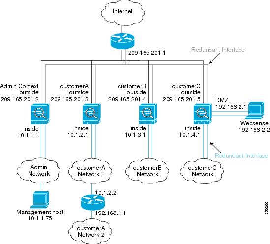
This configuration creates three security contexts plus the admin context, each with an inside and an outside interface. Both interfaces are configured as redundant interfaces.
The Customer C context includes a DMZ interface where a Websense server for HTTP filtering resides on the service provider premises (see Figure A-1).
Inside hosts can access the Internet through the outside using dynamic NAT or PAT, but no outside hosts can access the inside.
The Customer A context has a second network behind an inside router.
The admin context allows SSH sessions to the security appliance from one host.
Note
Figure A-1 Example 1
See the following sections for the configurations for this scenario:
•
•
•
•
•
System Configuration for Example 1
You must first enable multiple context mode using the mode multiple command. The mode is not stored in the configuration file, even though it endures reboots. Enter the show mode command to view the current mode.
hostname Farscapepassword passw0rdenable password chr1cht0nmac-address autoasdm image disk0:/asdm.binboot system disk0:/image.binadmin-context admininterface gigabitethernet 0/0no shutdowninterface gigabitethernet 0/1no shutdowninterface gigabitethernet 0/2no shutdowninterface gigabitethernet 0/3no shutdowninterface redundant 1member-interface gigabitethernet 0/0member-interface gigabitethernet 0/1interface redundant 2member-interface gigabitethernet 0/2member-interface gigabitethernet 0/3interface redundant 1.3vlan 3no shutdowninterface redundant 2.4vlan 4no shutdowninterface redundant 2.5vlan 5no shutdowninterface redundant 2.6vlan 6no shutdowninterface redundant 2.7vlan 7no shutdowninterface redundant 2.8vlan 8no shutdownclass goldlimit-resource rate conns 2000limit-resource conns 20000class silverlimit-resource rate conns 1000limit-resource conns 10000class bronzelimit-resource rate conns 500limit-resource conns 5000context adminallocate-interface redundant1.3 int1allocate-interface redundant2.4 int2config-url disk0://admin.cfgmember defaultcontext customerAdescription This is the context for customer Aallocate-interface redundant1.3 int1allocate-interface redundant2.5 int2config-url disk0://contexta.cfgmember goldcontext customerBdescription This is the context for customer Ballocate-interface redundant1.3 int1allocate-interface redundant2.6 int2config-url disk0://contextb.cfgmember silvercontext customerCdescription This is the context for customer Callocate-interface redundant1.3 int1allocate-interface redundant2.7-redundant2.8 int2-int3config-url disk0://contextc.cfgmember bronzeAdmin Context Configuration for Example 1
To change to a context configuration, enter the changeto context name command. To change back to the system, enter changeto system.
The host at 10.1.1.75 can access the context using SSH, which requires a key to be generated using the crypto key generate command.
hostname Admindomain example.cominterface int1nameif outsidesecurity-level 0ip address 209.165.201.2 255.255.255.224no shutdowninterface int2nameif insidesecurity-level 100ip address 10.1.1.1 255.255.255.0no shutdownpasswd secret1969enable password h1andl0route outside 0 0 209.165.201.1 1ssh 10.1.1.75 255.255.255.255 insidenat (inside) 1 10.1.1.0 255.255.255.0! This context uses dynamic NAT for inside users that access the outsideglobal (outside) 1 209.165.201.10-209.165.201.29! The host at 10.1.1.75 has access to the Websense server in Customer C, so! it needs a static translation for use in Customer C's access liststatic (inside,outside) 209.165.201.30 10.1.1.75 netmask 255.255.255.255Customer A Context Configuration for Example 1
To change to a context configuration, enter the changeto context name command. To change back to the system, enter changeto system.
interface int1nameif outsidesecurity-level 0ip address 209.165.201.3 255.255.255.224no shutdowninterface int2nameif insidesecurity-level 100ip address 10.1.2.1 255.255.255.0no shutdownpasswd hell0!enable password enter55route outside 0 0 209.165.201.1 1! The Customer A context has a second network behind an inside router that requires a! static route. All other traffic is handled by the default route pointing to the router.route inside 192.168.1.0 255.255.255.0 10.1.2.2 1nat (inside) 1 10.1.2.0 255.255.255.0! This context uses dynamic PAT for inside users that access that outside. The outside! interface address is used for the PAT addressglobal (outside) 1 interfaceCustomer B Context Configuration for Example 1
To change to a context configuration, enter the changeto context name command. To change back to the system, enter changeto system.
interface int1nameif outsidesecurity-level 0ip address 209.165.201.4 255.255.255.224no shutdowninterface int2nameif insidesecurity-level 100ip address 10.1.3.1 255.255.255.0no shutdownpasswd tenac10usenable password defen$eroute outside 0 0 209.165.201.1 1nat (inside) 1 10.1.3.0 255.255.255.0! This context uses dynamic PAT for inside users that access the outsideglobal (outside) 1 209.165.201.9 netmask 255.255.255.255access-list INTERNET remark Inside users only access HTTP and HTTPS servers on the outsideaccess-list INTERNET extended permit tcp any any eq httpaccess-list INTERNET extended permit tcp any any eq httpsaccess-group INTERNET in interface insideCustomer C Context Configuration for Example 1
To change to a context configuration, enter the changeto context name command. To change back to the system, enter changeto system.
interface int1nameif outsidesecurity-level 0ip address 209.165.201.5 255.255.255.224no shutdowninterface int2nameif insidesecurity-level 100ip address 10.1.4.1 255.255.255.0no shutdowninterface int3nameif dmzsecurity-level 50ip address 192.168.2.1 255.255.255.0no shutdownpasswd fl0werenable password treeh0u$eroute outside 0 0 209.165.201.1 1url-server (dmz) vendor websense host 192.168.2.2 url-block block 50url-cache dst 128filter url http 10.1.4.0 255.255.255.0 0 0! When inside users access an HTTP server, the security appliance consults with a! Websense server to determine if the traffic is allowednat (inside) 1 10.1.4.0 255.255.255.0! This context uses dynamic NAT for inside users that access the outsideglobal (outside) 1 209.165.201.9 netmask 255.255.255.255! A host on the admin context requires access to the Websense server for management using! pcAnywhere, so the Websense server uses a static translation for its private addressstatic (dmz,outside) 209.165.201.6 192.168.2.2 netmask 255.255.255.255access-list MANAGE remark Allows the management host to use pcAnywhere on the Websense serveraccess-list MANAGE extended permit tcp host 209.165.201.30 host 209.165.201.6 eq pcanywhere-dataaccess-list MANAGE extended permit udp host 209.165.201.30 host 209.165.201.6 eq pcanywhere-statusaccess-group MANAGE in interface outsideExample 2: Single Mode Firewall Using Same Security Level
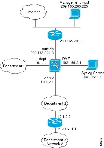
This configuration creates three internal interfaces. Two of the interfaces connect to departments that are on the same security level, which allows all hosts to communicate without using access lists. The DMZ interface hosts a syslog server. The management host on the outside needs access to the Syslog server and the security appliance. The security appliance uses RIP on the inside interfaces to learn routes. The security appliance does not advertise routes with RIP; the upstream router needs to use static routes for security appliance traffic (see Figure A-2).
The Department networks are allowed to access the Internet, and use PAT.
Threat detection is enabled.
Figure A-2 Example 2
passwd g00fba11enable password gen1u$hostname Busterasdm image disk0:/asdm.binboot system disk0:/image.bininterface gigabitethernet 0/0nameif outsidesecurity-level 0ip address 209.165.201.3 255.255.255.224no shutdowninterface gigabitethernet 0/1nameif dept2security-level 100ip address 10.1.2.1 255.255.255.0mac-address 000C.F142.4CDE standby 000C.F142.4CDFno shutdownrip authentication mode md5rip authentication key scorpius key_id 1interface gigabitethernet 0/2nameif dept1security-level 100ip address 10.1.1.1 255.255.255.0no shutdowninterface gigabitethernet 0/3nameif dmzsecurity-level 50ip address 192.168.2.1 255.255.255.0no shutdownsame-security-traffic permit inter-interfaceroute outside 0 0 209.165.201.1 1nat (dept1) 1 10.1.1.0 255.255.255.0nat (dept2) 1 10.1.2.0 255.255.255.0! The dept1 and dept2 networks use PAT when accessing the outsideglobal (outside) 1 209.165.201.9 netmask 255.255.255.255! Because we perform dynamic NAT on these addresses for outside access, we need to perform! NAT on them for all other interface access. This identity static statement just! translates the local address to the same address.static (dept1,dept2) 10.1.1.0 10.1.1.0 netmask 255.255.255.0static (dept2,dept1) 10.1.2.0 10.1.2.0 netmask 255.255.255.0! The syslog server uses a static translation so the outside management host can access! the serverstatic (dmz,outside) 209.165.201.5 192.168.2.2 netmask 255.255.255.255access-list MANAGE remark Allows the management host to access the syslog serveraccess-list MANAGE extended permit tcp host 209.165.200.225 host 209.165.201.5 eq sshaccess-group MANAGE in interface outside! Advertises the security appliance IP address as the default gateway for the downstream! router. The security appliance does not advertise a default route to the upstream! router. Listens for RIP updates from the downstream router. The security appliance does! not listen for RIP updates from the upstream router because a default route to the! upstream router is all that is required.router ripnetwork 10.0.0.0default information originateversion 2ssh 209.165.200.225 255.255.255.255 outsidelogging trap 5! System messages are sent to the syslog server on the DMZ networklogging host dmz 192.168.2.2logging enable! Enable basic threat detection:threat-detection basic-threatthreat-detection rate dos-drop rate-interval 600 average-rate 60 burst-rate 100! Enables scanning threat detection and automatically shun attackers,! except for hosts on the 10.1.1.0 network:threat-detection scanning-threat shun except ip-address 10.1.1.0 255.255.255.0threat-detection rate scanning-threat rate-interval 1200 average-rate 10 burst-rate 20threat-detection rate scanning-threat rate-interval 2400 average-rate 10 burst-rate 20! Enable statistics for access-lists:threat-detection statistics access-listExample 3: Shared Resources for Multiple Contexts
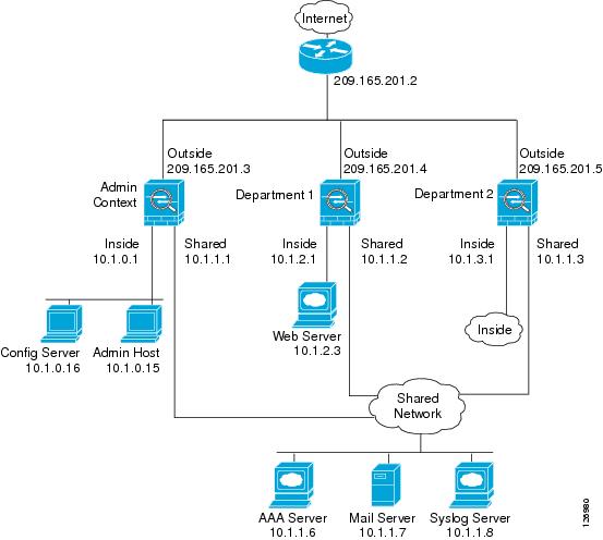
This configuration includes multiple contexts for multiple departments within a company. Each department has its own security context so that each department can have its own security policy. However, the syslog, mail, and AAA servers are shared across all departments. These servers are placed on a shared interface (see Figure A-3).
Department 1 has a web server that outside users who are authenticated by the AAA server can access.
Figure A-3 Example 3
See the following sections for the configurations for this scenario:
•
•
•
•
System Configuration for Example 3
You must first enable multiple context mode using the mode multiple command. The mode is not stored in the configuration file, even though it endures reboots. Enter the show mode command to view the current mode.
hostname Ubikpassword pkd55enable password deckard69asdm image disk0:/asdm.binboot system disk0:/image.binmac-address autoadmin-context admininterface gigabitethernet 0/0no shutdowninterface gigabitethernet 0/0.200! This is the shared outside interfacevlan 200no shutdowninterface gigabitethernet 0/1no shutdowninterface gigabitethernet 0/1.201! This is the inside interface for adminvlan 201no shutdowninterface gigabitethernet 0/1.202! This is the inside interface for department 1vlan 202no shutdowninterface gigabitethernet 0/1.203! This is the inside interface for department 2vlan 203no shutdowninterface gigabitethernet 0/1.300! This is the shared inside interfacevlan 300no shutdowncontext adminallocate-interface gigabitethernet 0/0.200allocate-interface gigabitethernet 0/1.201allocate-interface gigabitethernet 0/1.300config-url disk0://admin.cfgcontext department1allocate-interface gigabitethernet 0/0.200allocate-interface gigabitethernet 0/1.202allocate-interface gigabitethernet 0/1.300config-url ftp://admin:passw0rd@10.1.0.16/dept1.cfgcontext department2allocate-interface gigabitethernet 0/0.200allocate-interface gigabitethernet 0/1.203allocate-interface gigabitethernet 0/1.300config-url ftp://admin:passw0rd@10.1.0.16/dept2.cfgAdmin Context Configuration for Example 3
To change to a context configuration, enter the changeto context name command. To change back to the system, enter changeto system.
hostname Admininterface gigabitethernet 0/0.200nameif outsidesecurity-level 0ip address 209.165.201.3 255.255.255.224no shutdowninterface gigabitethernet 0/0.201nameif insidesecurity-level 100ip address 10.1.0.1 255.255.255.0no shutdowninterface gigabitethernet 0/0.300nameif sharedsecurity-level 50ip address 10.1.1.1 255.255.255.0no shutdownpasswd v00d00enable password d011route outside 0 0 209.165.201.2 1nat (inside) 1 10.1.0.0 255.255.255.0! This context uses PAT for inside users that access the outsideglobal (outside) 1 209.165.201.6 netmask 255.255.255.255! This context uses PAT for inside users that access the shared networkglobal (shared) 1 10.1.1.30! Because this host can access the web server in the Department 1 context, it requires a! static translationstatic (inside,outside) 209.165.201.7 10.1.0.15 netmask 255.255.255.255! Because this host has management access to the servers on the Shared interface, it! requires a static translation to be used in an access liststatic (inside,shared) 10.1.1.78 10.1.0.15 netmask 255.255.255.255access-list SHARED remark -Allows only mail traffic from inside to exit shared interfaceaccess-list SHARED remark -but allows the admin host to access any server.access-list SHARED extended permit ip host 10.1.1.78 anyaccess-list SHARED extended permit tcp host 10.1.1.30 host 10.1.1.7 eq smtp! Note that the translated addresses are used.access-group SHARED out interface shared! Allows 10.1.0.15 to access the admin context using Telnet. From the admin context, you! can access all other contexts.telnet 10.1.0.15 255.255.255.255 insideaaa-server AAA-SERVER protocol tacacs+aaa-server AAA-SERVER (shared) host 10.1.1.6key TheUauthKeyserver-port 16! The host at 10.1.0.15 must authenticate with the AAA server to log inaaa authentication telnet console AAA-SERVERaaa authorization command AAA-SERVER LOCALaaa accounting command AAA-SERVERlogging trap 6! System messages are sent to the syslog server on the Shared networklogging host shared 10.1.1.8logging enableDepartment 1 Context Configuration for Example 3
To change to a context configuration, enter the changeto context name command. To change back to the system, enter changeto system.
interface gigabitethernet 0/0.200nameif outsidesecurity-level 0ip address 209.165.201.4 255.255.255.224no shutdowninterface gigabitethernet 0/0.202nameif insidesecurity-level 100ip address 10.1.2.1 255.255.255.0no shutdowninterface gigabitethernet 0/0.300nameif sharedsecurity-level 50ip address 10.1.1.2 255.255.255.0no shutdownpasswd cugelenable password rhialtonat (inside) 1 10.1.2.0 255.255.255.0! The inside network uses PAT when accessing the outsideglobal (outside) 1 209.165.201.8 netmask 255.255.255.255! The inside network uses dynamic NAT when accessing the shared networkglobal (shared) 1 10.1.1.31-10.1.1.37! The web server can be accessed from outside and requires a static translationstatic (inside,outside) 209.165.201.9 10.1.2.3 netmask 255.255.255.255access-list WEBSERVER remark -Allows the management host (its translated address) on the access-list WEBSERVER remark -admin context to access the web server for managementaccess-list WEBSERVER remark -it can use any IP protocolaccess-list WEBSERVER extended permit ip host 209.165.201.7 host 209.165.201.9access-list WEBSERVER remark -Allows any outside address to access the web serveraccess-list WEBSERVER extended permit tcp any eq http host 209.165.201.9 eq httpaccess-group WEBSERVER in interface outsideaccess-list MAIL remark -Allows only mail traffic from inside to exit out the shared int! Note that the translated addresses are used.access-list MAIL extended permit tcp host 10.1.1.31 eq smtp host 10.1.1.7 eq smtpaccess-list MAIL extended permit tcp host 10.1.1.32 eq smtp host 10.1.1.7 eq smtpaccess-list MAIL extended permit tcp host 10.1.1.33 eq smtp host 10.1.1.7 eq smtpaccess-list MAIL extended permit tcp host 10.1.1.34 eq smtp host 10.1.1.7 eq smtpaccess-list MAIL extended permit tcp host 10.1.1.35 eq smtp host 10.1.1.7 eq smtpaccess-list MAIL extended permit tcp host 10.1.1.36 eq smtp host 10.1.1.7 eq smtpaccess-list MAIL extended permit tcp host 10.1.1.37 eq smtp host 10.1.1.7 eq smtpaccess-group MAIL out interface sharedaaa-server AAA-SERVER protocol tacacs+aaa-server AAA-SERVER (shared) host 10.1.1.6key TheUauthKeyserver-port 16! All traffic matching the WEBSERVER access list must authenticate with the AAA serveraaa authentication match WEBSERVER outside AAA-SERVERlogging trap 4! System messages are sent to the syslog server on the Shared networklogging host shared 10.1.1.8logging enableDepartment 2 Context Configuration for Example 3
To change to a context configuration, enter the changeto context name command. To change back to the system, enter changeto system.
interface gigabitethernet 0/0.200nameif outsidesecurity-level 0ip address 209.165.201.5 255.255.255.224no shutdowninterface gigabitethernet 0/0.203nameif insidesecurity-level 100ip address 10.1.3.1 255.255.255.0no shutdowninterface gigabitethernet 0/0.300nameif sharedsecurity-level 50ip address 10.1.1.3 255.255.255.0no shutdownpasswd maz1r1anenable password ly0ne$$eroute outside 0 0 209.165.201.2 1nat (inside) 1 10.1.3.0 255.255.255.0! The inside network uses PAT when accessing the outsideglobal (outside) 1 209.165.201.10 netmask 255.255.255.255! The inside network uses PAT when accessing the shared networkglobal (shared) 1 10.1.1.38access-list MAIL remark -Allows only mail traffic from inside to exit out the shared intaccess-list MAIL extended permit tcp host 10.1.1.38 host 10.1.1.7 eq smtp! Note that the translated PAT address is used.access-group MAIL out interface sharedlogging trap 3! System messages are sent to the syslog server on the Shared networklogging host shared 10.1.1.8logging enableExample 4: Multiple Mode, Transparent Firewall with Outside Access
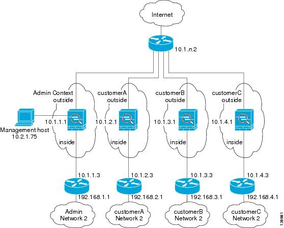
This configuration creates three security contexts plus the admin context. Each context allows OSPF traffic to pass between the inside and outside routers (see Figure A-4).
Inside hosts can access the Internet through the outside, but no outside hosts can access the inside.
An out-of-band management host is connected to the Management 0/0 interface.
The admin context allows SSH sessions to the security appliance from one host.
Connection limit settings for each context, except admin, limit the number of connections to guard against DoS attacks.
Note
Figure A-4 Example 4
See the following sections for the configurations for this scenario:
•
•
•
•
•
System Configuration for Example 4
You must first enable multiple context mode using the mode multiple command. The mode is not stored in the configuration file, even though it endures reboots. Enter the show mode command to view the current mode.
firewall transparenthostname Farscapepassword passw0rdenable password chr1cht0nasdm image disk0:/asdm.binboot system disk0:/image.binmac-address autoadmin-context admininterface gigabitethernet 0/0no shutdowninterface gigabitethernet 0/0.150vlan 150no shutdowninterface gigabitethernet 0/0.151vlan 151no shutdowninterface gigabitethernet 0/0.152vlan 152no shutdowninterface gigabitethernet 0/0.153vlan 153no shutdowninterface gigabitethernet 0/1shutdowninterface gigabitethernet 0/1.4vlan 4no shutdowninterface gigabitethernet 0/1.5vlan 5no shutdowninterface gigabitethernet 0/1.6vlan 6no shutdowninterface gigabitethernet 0/1.7vlan 7no shutdowninterface management 0/0no shutdowncontext adminallocate-interface gigabitethernet 0/0.150allocate-interface gigabitethernet 0/1.4allocate-interface management 0/0config-url disk0://admin.cfgcontext customerAdescription This is the context for customer Aallocate-interface gigabitethernet 0/0.151allocate-interface gigabitethernet 0/1.5config-url disk0://contexta.cfgcontext customerBdescription This is the context for customer Ballocate-interface gigabitethernet 0/0.152allocate-interface gigabitethernet 0/1.6config-url disk0://contextb.cfgcontext customerCdescription This is the context for customer Callocate-interface gigabitethernet 0/0.153allocate-interface gigabitethernet 0/1.7config-url disk0://contextc.cfgAdmin Context Configuration for Example 4
To change to a context configuration, enter the changeto context name command. To change back to the system, enter changeto system.
The host at 10.2.1.75 can access the context using SSH, which requires a key pair to be generated using the crypto key generate command.
hostname Admindomain example.cominterface gigabitethernet 0/0.150nameif outsidesecurity-level 0no shutdowninterface gigabitethernet 0/1.4nameif insidesecurity-level 100no shutdowninterface management 0/0nameif managesecurity-level 50! Unlike other transparent interfaces, the management interface! requires an IP address:ip address 10.2.1.1 255.255.255.0no shutdownpasswd secret1969enable password h1andl0ip address 10.1.1.1 255.255.255.0route outside 0 0 10.1.1.2 1ssh 10.2.1.75 255.255.255.255 manageaccess-list OSPF remark -Allows OSPFaccess-list OSPF extended permit 89 any anyaccess-group OSPF in interface outsideCustomer A Context Configuration for Example 4
To change to a context configuration, enter the changeto context name command. To change back to the system, enter changeto system.
interface gigabitethernet 0/0.151nameif outsidesecurity-level 0no shutdowninterface gigabitethernet 0/1.5nameif insidesecurity-level 100no shutdownpasswd hell0!enable password enter55ip address 10.1.2.1 255.255.255.0route outside 0 0 10.1.2.2 1access-list OSPF remark -Allows OSPFaccess-list OSPF extended permit 89 any anyaccess-group OSPF in interface outsideCustomer B Context Configuration for Example 4
To change to a context configuration, enter the changeto context name command. To change back to the system, enter changeto system.
interface gigabitethernet 0/0.152nameif outsidesecurity-level 0no shutdowninterface gigabitethernet 0/1.6nameif insidesecurity-level 100no shutdownpasswd tenac10usenable password defen$eip address 10.1.3.1 255.255.255.0route outside 0 0 10.1.3.2 1access-list OSPF remark -Allows OSPFaccess-list OSPF extended permit 89 any anyaccess-group OSPF in interface outside! The following commands add connection limits to the global policy.class-map conn_limitsmatch anypolicy-map global_policyclass conn_limitsset connection conn-max 5000 embryonic-conn-max 2000set connection timeout tcp 2:0:0 reset half-close 0:5:0 embryonic 0:0:20 dcd 20 3service-policy global_policy globalCustomer C Context Configuration for Example 4
To change to a context configuration, enter the changeto context name command. To change back to the system, enter changeto system.
interface gigabitethernet 0/0.153nameif outsidesecurity-level 0no shutdowninterface gigabitethernet 0/1.7nameif insidesecurity-level 100no shutdownpasswd fl0werenable password treeh0u$eip address 10.1.4.1 255.255.255.0route outside 0 0 10.1.4.2 1access-list OSPF remark -Allows OSPFaccess-list OSPF extended permit 89 any anyaccess-group OSPF in interface outside! The following commands add connection limits to the global policy.class-map conn_limitsmatch anypolicy-map global_policyclass conn_limitsset connection conn-max 5000 embryonic-conn-max 2000set connection timeout tcp 2:0:0 reset half-close 0:5:0 embryonic 0:0:20 dcd 20 3service-policy global_policy globalExample 5: Single Mode, Transparent Firewall with NAT
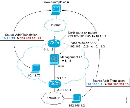
This configuration shows how to configure NAT in transparent mode (see Figure A-5).
Figure A-5 Example 5
The host at 10.1.1.75 can access the security appliance using SSH, which requires a key pair to be generated using the crypto key generate command.
firewall transparenthostname Farscapepassword passw0rdenable password chr1cht0nasdm image disk0:/asdm.binboot system disk0:/image.binhostname Moyadomain example.cominterface gigabitethernet 0/0nameif outsidesecurity-level 0no shutdowninterface gigabitethernet 0/1nameif insidesecurity-level 100no shutdownip address 10.1.1.1 255.255.255.0route outside 0 0 10.1.1.2 1! The following route is required when you perform NAT! on non-directly-connected networks:route inside 192.168.1.0 255.255.255.0 10.1.1.3 1ssh 10.1.1.75 255.255.255.255 insidenat (inside) 1 10.1.1.0 255.255.255.0nat (inside) 1 198.168.1.0 255.255.255.0global (outside) 1 209.165.201.1-209.165.201.15Example 6: IPv6 Configuration
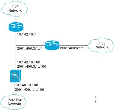
This sample configuration shows several features of IPv6 support on the security appliance:
•
•
•
•
•
•
Figure A-6 IPv6 Dual Stack Configuration
enable password myenablepasswordpasswd mypasswordhostname coyupixasdm image flash:/asdm.binboot system flash:/image.bininterface gigabitethernet0/0nameif outsidesecurity-level 0ip address 10.142.10.100 255.255.255.0ipv6 address 2001:400:3:1::100/64ipv6 nd suppress-raospf mtu-ignore autono shutdowninterface gigabitethernet0/1nameif insidesecurity-level 100ip address 10.140.10.100 255.255.255.0ipv6 address 2001:400:1:1::100/64ospf mtu-ignore autono shutdownaccess-list allow extended permit icmp any anyssh 10.140.10.75 255.255.255.255 insidelogging enablelogging buffered debuggingipv6 enforce-eui64 insideipv6 route outside 2001:400:6:1::/64 2001:400:3:1::1ipv6 route outside ::/0 2001:400:3:1::1ipv6 access-list outacl permit icmp6 2001:400:2:1::/64 2001:400:1:1::/64ipv6 access-list outacl permit tcp 2001:400:2:1::/64 2001:400:1:1::/64 eq telnetipv6 access-list outacl permit tcp 2001:400:2:1::/64 2001:400:1:1::/64 eq ftpipv6 access-list outacl permit tcp 2001:400:2:1::/64 2001:400:1:1::/64 eq wwwaccess-group allow in interface outsideaccess-group outacl in interface outsideroute outside 0.0.0.0 0.0.0.0 16.142.10.1 1Example 7: Dual ISP Support Using Static Route Tracking
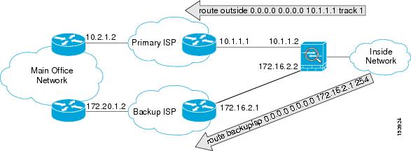
This configuration shows a remote office using static route tracking to use a backup ISP route if the primary ISP route fails. The security appliance in the remote office uses ICMP echo requests to monitor the availability of the main office gateway. If that gateway becomes unavailable through the default route, the default route is removed from the routing table and the floating route to the backup ISP is used in its place.
Figure A-7 Dual ISP Support
passwd password1enable password password2hostname myfirewallasdm image disk0:/asdm.binboot system disk0:/image.bin!interface gigabitethernet 0/0nameif outsidesecurity-level 0ip address 10.1.1.2 255.255.255.0no shutdown!interface gigabitethernet 0/1description backup isp linknameif backupispsecurity-level 100ip address 172.16.2.2 255.255.255.0no shutdown!sla monitor 123type echo protocol ipIcmpEcho 10.2.1.2 interface outsidenum-packets 3timeout 1000frequency 3sla monitor schedule 123 life forever start-time now!track 1 rtr 123 reachability!route outside 0.0.0.0 0.0.0.0 10.1.1.1 track 1! The above route is used while the tracked object, router 10.2.1.2! is available. It is removed when the router becomes unavailable.!route backupisp 0.0.0.0 0.0.0.0 172.16.2.1 254! The above route is a floating static route that is added to the! routing table when the tracked route is removed.Example 8: Multicast Routing
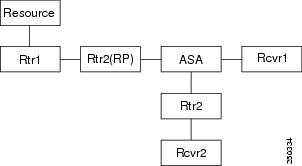
This configuration shows a source that is sending out multicast traffic with two listeners that are watching for messages. A network lies between the source and the receivers, and all devices need to build up the PIM tree properly for the traffic to flow. This includes the ASA 5505 adaptive security appliance, and all IOS routers.
Figure A-8 Multicast Routing Configuration
Note
For PIM Sparse Mode
This configuration enables multicast routing for PIM Sparse Mode.
hostname asamulticast-routinginterface GigabitEthernet0/0nameif outsidesecurity-level 0ip address 10.1.1.1 255.255.255.0interface GigabitEthernet0/1nameif insidesecurity-level 100ip address 10.1.2.1 255.255.255.0interface GigabitEthernet0/2nameif dmzsecurity-level 50ip address 10.1.3.1 255.255.255.0igmp join-group 227.1.2.3! Specify the RPpim rp-address 10.1.1.2! Specify ACL configuration on the interfacesaccess-list mcast permit pim any anyaccess-list mcast permit igmp any anyaccess-list mcast permit ospf any anyaccess-list mcast permit icmp any anyaccess-list mcast permit tcp any any eq 80access-list mcast permit udp any 224.0.0.0 240.0.0.0no failoveraccess-group mcast in interface outsideaccess-group mcast in interface insideaccess-group mcast in interface dmz! Configures unicast routingrouter ospf 1network 10.1.1.0 255.255.255.0 area 0network 10.1.2.0 255.255.255.0 area 0network 10.1.3.0 255.255.255.0 area 0log-adj-changes!For PIM bidir Mode
hostname asamulticast-routing!interface GigabitEthernet0/0nameif outsidesecurity-level 0ip address 10.1.1.1 255.255.255.0!interface GigabitEthernet0/1nameif insidesecurity-level 100ip address 10.1.2.1 255.255.255.0!interface GigabitEthernet0/2nameif dmzsecurity-level 50ip address 10.1.3.1 255.255.255.0igmp join-group 227.1.2.3! Specify the RP
pim rp-address 10.1.1.2 bidir! Specify ACL configuration on the interfacesaccess-list mcast permit pim any anyaccess-list mcast permit igmp any anyaccess-list mcast permit ospf any anyaccess-list mcast permit icmp any anyaccess-list mcast permit tcp any any eq 80access-list mcast permit udp any 224.0.0.0 240.0.0.0no failoveraccess-group mcast in interface outsideaccess-group mcast in interface insideaccess-group mcast in interface dmz! Configures unicast routingrouter ospf 1network 10.1.1.0 255.255.255.0 area 0network 10.1.2.0 255.255.255.0 area 0network 10.1.3.0 255.255.255.0 area 0log-adj-changesExample 9: LAN-Based Active/Standby Failover (Routed Mode)
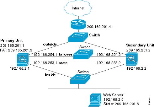
Figure A-9 shows the network diagram for a failover configuration using an Ethernet failover link. The units are configured to detect unit failures and to fail over in under a second (see the failover polltime unit command in the primary unit configuration).
Figure A-9 LAN-Based Failover Configuration
See the following sections for primary or secondary unit configuration scenarios:
•
•
Primary Unit Configuration for Example 9
hostname pixfirewallenable password myenablepasswordpassword mypasswordinterface gigabitethernet0/0nameif outsideip address 209.165.201.1 255.255.255.224 standby 209.165.201.2no shutdowninterface gigabitethernet0/1nameif insideip address 192.168.2.1 255.255.255.0 standby 192.168.2.2no shutdowninterface gigabitethernet0/2description LAN Failover Interfaceno shutdowninterface gigabitethernet0/3description STATE Failover Interfacetelnet 192.168.2.45 255.255.255.255 insideaccess-list acl_out permit tcp any host 209.165.201.5 eq 80failoverfailover lan unit primaryfailover lan interface failover gigabitethernet0/2failover lan enable! The failover lan enable command is required on the PIX security appliance only.failover polltime unit msec 200 holdtime msec 800failover key key1failover link state gigabitethernet0/3failover interface ip failover 192.168.254.1 255.255.255.0 standby 192.168.254.2failover interface ip state 192.168.253.1 255.255.255.0 standby 192.168.253.2global (outside) 1 209.165.201.3 netmask 255.255.255.224nat (inside) 1 0.0.0.0 0.0.0.0static (inside,outside) 209.165.201.5 192.168.2.5 netmask 255.255.255.255 0 0access-group acl_out in interface outsideroute outside 0.0.0.0 0.0.0.0 209.165.201.4 1Secondary Unit Configuration for Example 9
failoverfailover lan unit secondaryfailover lan interface failover gigabitethernet0/2failover lan enablefailover key key1failover interface ip failover 192.168.254.1 255.255.255.0 standby 192.168.254.2Example 10: LAN-Based Active/Active Failover (Routed Mode)
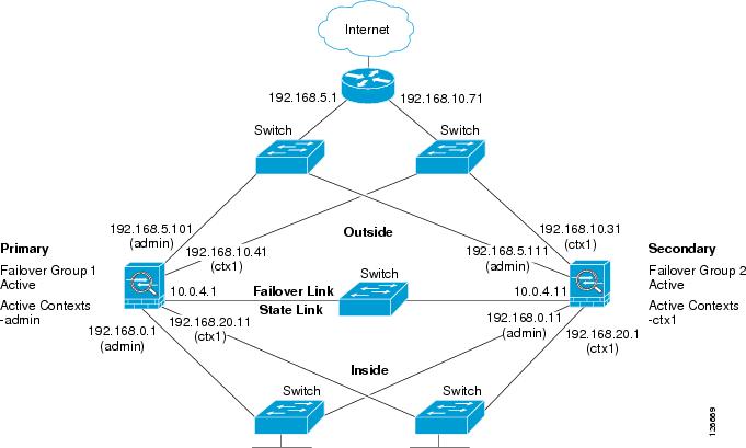
The following example shows how to configure Active/Active failover. In this example there are 2 user contexts, named admin and ctx1. Figure A-10 shows the network diagram for the example.
Figure A-10 Active/Active Failover Configuration
See the following sections for the configurations for this scenario:
•
•
Primary Unit Configuration for Example 10
See the following sections for the primary unit configuration:
•
•
•
Primary System Configuration for Example 10
You must first enable multiple context mode using the mode multiple command. The mode is not stored in the configuration file, even though it endures reboots. Enter the show mode command to view the current mode.
hostname ciscopixenable password farscapepassword crichtonasdm image flash:/asdm.binboot system flash:/cdisk.binmac-address autointerface gigabitethernet0/0description LAN/STATE Failover Interfaceinterface gigabitethernet0/1no shutdowninterface gigabitethernet0/2no shutdowninterface gigabitethernet0/3no shutdowninterface gigabitethernet1/0no shutdowninterface gigabitethernet1/1no shutdowninterface gigabitethernet1/2no shutdowninterface gigabitethernet1/3no shutdownfailoverfailover lan unit primaryfailover lan interface folink gigabitethernet0/0failover link folink gigabitethernet0/0failover interface ip folink 10.0.4.1 255.255.255.0 standby 10.0.4.11failover group 1primarypreempt 60failover group 2secondarypreempt 60admin-context admincontext admindescription adminallocate-interface gigabitethernet0/1allocate-interface gigabitethernet0/2config-url flash:/admin.cfgjoin-failover-group 1context ctx1description context 1allocate-interface gigabitethernet0/3allocate-interface gigabitethernet1/0config-url flash:/ctx1.cfgjoin-failover-group 2Primary admin Context Configuration for Example 10
To change to a context configuration, enter the changeto context name command. To change back to the system, enter changeto system.
enable password frekpassword elixirhostname admininterface gigabitethernet0/1nameif outsidesecurity-level 0ip address 192.168.5.101 255.255.255.0 standby 192.168.5.111interface gigabitethernet0/2nameif insidesecurity-level 100ip address 192.168.0.1 255.255.255.0 standby 192.168.0.11monitor-interface outsidemonitor-interface insideroute outside 0.0.0.0 0.0.0.0 192.168.5.1 1ssh 192.168.0.2 255.255.255.255 insidePrimary ctx1 Context Configuration for Example 10
To change to a context configuration, enter the changeto context name command. To change back to the system, enter changeto system.
enable password quadropheniapassword tommyhostname ctx1interface gigabitethernet0/3nameif insidesecurity-level 100ip address 192.168.20.1 255.255.255.0 standby 192.168.20.11interface gigabitethernet1/0nameif outsidesecurity-level 0ip address 192.168.10.31 255.255.255.0 standby 192.168.10.41asr-group 1access-list 201 extended permit ip any anyaccess-group 201 in interface outsidelogging enablelogging console informationalmonitor-interface insidemonitor-interface outsideroute outside 0.0.0.0 0.0.0.0 192.168.10.71 1Secondary Unit Configuration for Example 10
You only need to configure the secondary security appliance to recognize the failover link. The secondary security appliance obtains the context configurations from the primary security appliance upon booting or when failover is first enabled. The preempt commands in the failover group configurations cause the failover groups to become active on their designated unit after the configurations have been synchronized and the preempt delay has passed.
failoverfailover lan unit secondaryfailover lan interface folink gigabitethernet0/0failover interface ip folink 10.0.4.1 255.255.255.0 standby 10.0.4.11Example 11: LAN-Based Active/Standby Failover (Transparent Mode)
Figure A-11 shows the network diagram for a transparent mode failover configuration using an Ethernet failover link. The units are configured to detect unit failures and to fail over in under a second (see the failover polltime unit command in the primary unit configuration).
Figure A-11 Transparent Mode LAN-Based Failover Configuration
See the following sections for the configurations for this scenario:
•
•
Primary Unit Configuration for Example 11
firewall transparenthostname pixfirewallenable password myenablepasswordpassword mypasswordinterface gigabitethernet0/0nameif outsideno shutdowninterface gigabitethernet0/1nameif insideno shutdowninterface gigabitethernet0/2description LAN Failover Interfaceno shutdowninterface gigabitethernet0/3description STATE Failover Interfacetelnet 192.168.2.45 255.255.255.255 insideaccess-list acl_out permit tcp any host 209.165.201.5 eq 80ip address 209.165.201.1 255.255.255.0 standby 209.165.201.2failoverfailover lan unit primaryfailover lan interface failover gigabitethernet0/2failover lan enable! The failover lan enable command is required on the PIX security appliance only.failover polltime unit msec 200 holdtime msec 800failover key key1failover link state gigabitethernet0/3failover interface ip failover 192.168.254.1 255.255.255.0 standby 192.168.254.2failover interface ip state 192.168.253.1 255.255.255.0 standby 192.168.253.2access-group acl_out in interface outsideroute outside 0.0.0.0 0.0.0.0 209.165.201.4 1Secondary Unit Configuration for Example 11
firewall transparentfailoverfailover lan unit secondaryfailover lan interface failover gigabitethernet0/2failover lan enablefailover key key1failover interface ip failover 192.168.254.1 255.255.255.0 standby 192.168.254.2Example 12: LAN-Based Active/Active Failover (Transparent Mode)
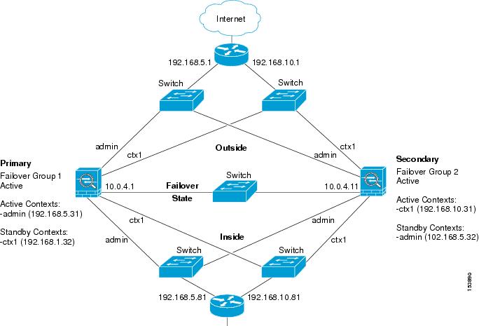
The following example shows how to configure transparent mode Active/Active failover. In this example there are 2 user contexts, named admin and ctx1. Figure A-12 shows the network diagram for the example.
Figure A-12 Transparent Mode Active/Active Failover Configuration
See the following sections for the configurations for this scenario:
•
•
Primary Unit Configuration for Example 12
See the following sections for the primary unit configuration:
•
•
•
Primary System Configuration for Example 12
You must first enable multiple context mode using the mode multiple command. The mode is not stored in the configuration file, even though it endures reboots. Enter the show mode command to view the current mode.
firewall transparenthostname ciscopixenable password farscapepassword crichtonasdm image flash:/asdm.binboot system flash:/cdisk.binmac-address autointerface gigabitethernet0/0description LAN/STATE Failover Interfaceinterface gigabitethernet0/1no shutdowninterface gigabitethernet0/2no shutdowninterface gigabitethernet0/3no shutdowninterface gigabitethernet1/0no shutdowninterface gigabitethernet1/1no shutdowninterface gigabitethernet1/2no shutdowninterface gigabitethernet1/3no shutdownfailoverfailover lan unit primaryfailover lan interface folink gigabitethernet0/0failover link folink gigabitethernet0/0failover interface ip folink 10.0.4.1 255.255.255.0 standby 10.0.4.11failover group 1primarypreemptfailover group 2secondarypreemptadmin-context admincontext admindescription adminallocate-interface gigabitethernet0/1allocate-interface gigabitethernet0/2config-url flash:/admin.cfgjoin-failover-group 1context ctx1description context 1allocate-interface gigabitethernet0/3allocate-interface gigabitethernet1/0config-url flash:/ctx1.cfgjoin-failover-group 2Primary admin Context Configuration for Example 12
To change to a context configuration, enter the changeto context name command. To change back to the system, enter changeto system.
enable password frekpassword elixirhostname admininterface gigabitethernet0/1nameif outsidesecurity-level 0interface gigabitethernet0/2nameif insidesecurity-level 100ip address 192.168.5.31 255.255.255.0 standby 192.168.5.32monitor-interface outsidemonitor-interface insideroute outside 0.0.0.0 0.0.0.0 192.168.5.1 1ssh 192.168.5.72 255.255.255.255 insidePrimary ctx1 Context Configuration for Example 12
To change to a context configuration, enter the changeto context name command. To change back to the system, enter changeto system.
enable password quadropheniapassword tommyhostname ctx1interface gigabitethernet0/3nameif insidesecurity-level 100interface gigabitethernet1/0nameif outsidesecurity-level 0access-list 201 extended permit ip any anyaccess-group 201 in interface outsidelogging enablelogging console informationalip address 192.168.10.31 255.255.255.0 standby 192.168.10.32monitor-interface insidemonitor-interface outsideroute outside 0.0.0.0 0.0.0.0 192.168.10.1 1Secondary Unit Configuration for Example 12
You only need to configure the secondary security appliance to recognize the failover link. The secondary security appliance obtains the context configurations from the primary security appliance upon booting or when failover is first enabled. The preempt commands in the failover group configurations cause the failover groups to become active on their designated unit after the configurations have been synchronized and the preempt delay has passed.
firewall transparentfailoverfailover lan unit secondaryfailover lan interface folink gigabitethernet0/0failover interface ip folink 10.0.4.1 255.255.255.0 standby 10.0.4.11Example 13: Cable-Based Active/Standby Failover (Routed Mode)
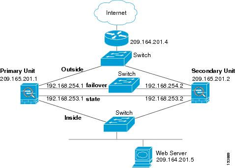
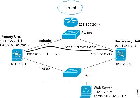
Figure A-13 shows the network diagram for a failover configuration using a serial Failover cable. This configuration is only available on the PIX security appliance. This example also specifies a stateful failover configuration.
Figure A-13 Cable-Based Failover Configuration
The following are the typical commands in a cable-based failover configuration.
enable password myenablepasswordpasswd mypasswordhostname pixfirewallasdm image flash:/asdm.binboot system flash:/image.bininterface Ethernet0nameif outsidesecurity-level 0speed 100duplex fullip address 209.165.201.1 255.255.255.224 standby 209.165.201.2no shutdowninterface Ethernet1nameif insidesecurity-level 100speed 100duplex fullip address 192.168.2.1 255.255.255.0 standby 192.168.2.2no shutdowninterface Ethernet3description STATE Failover Interfacetelnet 192.168.2.45 255.255.255.255 insideaccess-list acl_in permit tcp any host 209.165.201.5 eq 80access-group acl_in in interface outsidefailover! Enables cable-based failover on the PIX security appliancefailover link state Ethernet3failover interface ip state 192.168.253.1 255.255.255.252 standby 192.168.253.2! The previous two lines are necessary for a stateful failoverglobal (outside) 1 209.165.201.3 netmask 255.255.255.224nat (inside) 1 0.0.0.0 0.0.0.0static (inside,outside) 209.165.201.5 192.168.2.5 netmask 255.255.255.255 0 0route outside 0.0.0.0 0.0.0.0 209.165.201.4 1Example 14: Cable-Based Active/Standby Failover (Transparent Mode)
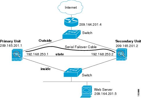
Figure A-14 shows the network diagram for a transparent mode failover configuration using a serial Failover cable. This configuration is only available on the PIX 500 series security appliance.
Figure A-14 Transparent Mode Cable-Based Failover Configuration
The following are the typical commands in a cable-based, transparent firewall failover configuration.
enable password myenablepasswordpasswd mypasswordhostname pixfirewallasdm image flash:/asdm.binboot system flash:/image.binfirewall transparentinterface Ethernet0speed 100duplex fullnameif outsidesecurity-level 0no shutdowninterface Ethernet1speed 100duplex fullnameif insidesecurity-level 100no shutdowninterface Ethernet3description STATE Failover Interfacetelnet 192.168.2.45 255.255.255.255 mgmtaccess-list acl_in permit tcp any host 209.165.201.5 eq 80access-group acl_in in interface outsideip address 209.165.201.1 255.255.255.0 standby 209.165.201.2failoverfailover link state Ethernet3failover interface ip state 192.168.253.1 255.255.255.0 standby 192.168.253.2route outside 0.0.0.0 0.0.0.0 209.165.201.4 1Example 15: ASA 5505 Base License
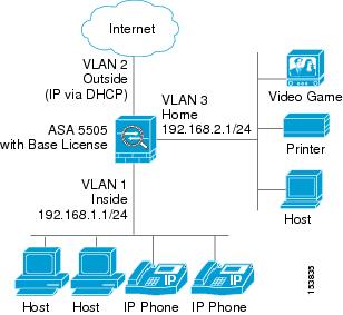
This configuration creates three VLANs: inside (business), outside (Internet), and home (see Figure A-15). Both the home and inside VLANs can access the outside, but the home VLAN cannot access the inside VLAN. The inside VLAN can access the home VLAN so both VLANs can share a printer. Because the outside IP address is set using DHCP, the inside and home VLANs use interface PAT when accessing the Internet.
Figure A-15 ASA 5505 Base License
passwd g00fba11enable password gen1u$hostname Busterasdm image disk0:/asdm.binboot system disk0:/image.bininterface vlan 2nameif outsidesecurity-level 0ip address dhcp setrouteno shutdowninterface vlan 1nameif insidesecurity-level 100ip address 192.168.1.1 255.255.255.0no shutdowninterface vlan 3! This interface cannot communicate with the inside interface. This is required using! the Base licenseno forward interface vlan 1nameif homesecurity-level 50ip address 192.168.2.1 255.255.255.0no shutdowninterface ethernet 0/0switchport access vlan 2no shutdowninterface ethernet 0/1switchport access vlan 1no shutdowninterface ethernet 0/2switchport access vlan 1no shutdowninterface ethernet 0/3switchport access vlan 3no shutdowninterface ethernet 0/4switchport access vlan 3no shutdowninterface ethernet 0/5switchport access vlan 3no shutdowninterface ethernet 0/6description PoE for IP phone1switchport access vlan 1no shutdowninterface ethernet 0/7description PoE for IP phone2switchport access vlan 1no shutdownnat (inside) 1 0 0nat (home) 1 0 0global (outside) 1 interface! The previous NAT statements match all addresses on inside and home, so you need to! also perform NAT when hosts access the inside or home networks (as well as the outside). ! Or you can exempt hosts from NAT for inside <--> home traffic, as effected by the! following:access-list natexmpt-inside extended permit ip any 192.168.2.0 255.255.255.0access-list natexmpt-home extended permit ip any 192.168.1.0 255.255.255.0nat (inside) 0 access-list natexmpt-insidenat (home) 0 access-list natexmpt-homehttp server enablehttp 192.168.1.0 255.255.255.0 insidedhcpd address 192.168.1.2-192.168.1.254 insidedhcpd auto_config outsidedhcpd enable insidelogging asdm informationalssh 192.168.1.0 255.255.255.0 insideExample 16: ASA 5505 Security Plus License with Failover and Dual-ISP Backup
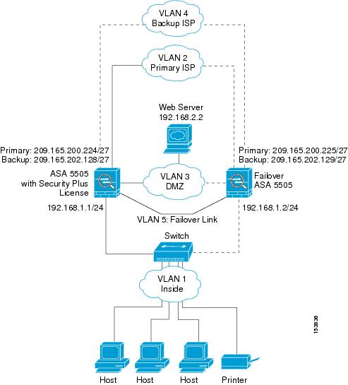
This configuration creates five VLANs: inside, outside, dmz, backup-isp and faillink (see Figure A-16).
Figure A-16 ASA 5505 Security Plus License with Failover and Dual-ISP Backup
See the following sections for the configurations for this scenario:
•
•
Primary Unit Configuration for Example 16
passwd g00fba11enable password gen1u$hostname Busterasdm image disk0:/asdm.binboot system disk0:/image.bininterface vlan 2description Primary ISP interfacenameif outsidesecurity-level 0ip address 209.165.200.224 standby 209.165.200.225backup interface vlan 4no shutdowninterface vlan 1nameif insidesecurity-level 100ip address 192.168.1.1 255.255.255.0no shutdowninterface vlan 3nameif dmzsecurity-level 50ip address 192.168.2.1 255.255.255.0no shutdowninterface vlan 4description Backup ISP interfacenameif backup-ispsecurity-level 0ip address 209.168.202.128 standby 209.168.202.129no shutdowninterface vlan 5description LAN Failover Interfaceinterface ethernet 0/0switchport access vlan 2no shutdowninterface ethernet 0/1switchport access vlan 4no shutdowninterface ethernet 0/2switchport access vlan 1no shutdowninterface ethernet 0/3switchport access vlan 3no shutdowninterface ethernet 0/4switchport access vlan 5no shutdownfailoverfailover lan unit primaryfailover lan interface faillink vlan5failover lan faillink vlan5failover polltime unit 3 holdtime 10failover key key1failover interface ip faillink 10.1.1.1 255.255.255.0 standby 10.1.1.2nat (inside) 1 0 0nat (home) 1 0 0global (outside) 1 interface! The previous NAT statements match all addresses on inside and home, so you need to! also perform NAT when hosts access the inside or home networks (as well as the outside). ! Or you can exempt hosts from NAT for inside <--> home traffic, as effected by the! following:access-list natexmpt-inside extended permit ip any 192.168.2.0 255.255.255.0access-list natexmpt-home extended permit ip any 192.168.1.0 255.255.255.0nat (inside) 0 access-list natexmpt-insidenat (home) 0 access-list natexmpt-homesla monitor 123type echo protocol ipIcmpEcho 209.165.200.234 interface outsidenum-packets 2frequency 5sla monitor schedule 123 life forever start-time nowtrack 1 rtr 123 reachabilityroute outside 0 0 209.165.200.234 1 track 1! This route is for the primary ISP.route backup-isp 0 0 209.165.202.154 2! If the link goes down for the primary ISP, either due to a hardware failure! or unplugged cable, then this route will be used.http server enablehttp 192.168.1.0 255.255.255.0 insidedhcpd address 192.168.1.2-192.168.1.254 insidedhcpd auto_config outsidedhcpd enable insidelogging asdm informationalssh 192.168.1.0 255.255.255.0 insideSecondary Unit Configuration for Example 16
You only need to configure the secondary security appliance to recognize the failover link. The secondary security appliance obtains the context configurations from the primary security appliance upon booting or when failover is first enabled.
interface ethernet 0/4switchport access vlan 5no shutdownfailoverfailover lan unit secondaryfailover lan interface faillink vlan5failover polltime unit 3 holdtime 10failover key key1failover interface ip faillink 10.1.1.1 255.255.255.0 standby 10.1.1.2Example 17: AIP SSM in Multiple Context Mode
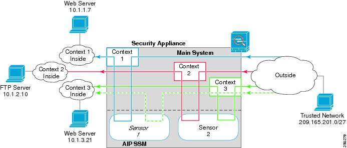
This configuration assigns two virtual IPS sensors to three contexts. Context 1 uses sensor 1, context 2 uses sensor 2 (for greater security), and context 3 uses sensor 2 for most traffic, but uses sensor 1 for a more trusted outside network (see Figure A-17).
For Context 1, only the trusted network is allowed to access a web server and manage the context using SSH.
For Context 2, any outside user can access the FTP server.
For Context 3, any outside user can access the web server, but the trusted network can access anything on the inside network.
Figure A-17 Security Contexts and Virtual Sensors
See the following sections for the configurations for this scenario:
•
•
•
•
System Configuration for Example 17
You must first enable multiple context mode using the mode multiple command. The mode is not stored in the configuration file, even though it endures reboots. Enter the show mode command to view the current mode.
hostname Farscapepassword passw0rdenable password chr1cht0nmac-address autoasdm image disk0:/asdm.binboot system disk0:/image.binadmin-context context 1interface gigabitethernet 0/0no shutdowninterface gigabitethernet 0/1no shutdowninterface gigabitethernet 0/2no shutdowninterface gigabitethernet 0/3no shutdowncontext 1allocate-interface gigabitethernet0/0allocate-interface gigabitethernet0/3allocate-ips sensor1config-url ftp://user1:passw0rd@10.1.1.1/configlets/context1.cfgcontext 2allocate-interface gigabitethernet0/1allocate-interface gigabitethernet0/3allocate-ips sensor2config-url ftp://user1:passw0rd@10.1.1.1/configlets/context2.cfgcontext 3allocate-interface gigabitethernet0/2allocate-interface gigabitethernet0/3allocate-ips sensor1allocate-ips sensor2 defaultconfig-url ftp://user1:passw0rd@10.1.1.1/configlets/context3.cfgContext 1 Configuration for Example 17
To change to a context configuration, enter the changeto context name command. To change back to the system, enter changeto system.
hostname context1domain example.cominterface gigabitethernet 0/3nameif outsidesecurity-level 0ip address 209.165.200.225 255.255.255.224no shutdowninterface gigabitethernet 0/0nameif insidesecurity-level 100ip address 10.1.1.1 255.255.255.0no shutdownpasswd seaandsandenable password pinballwizardroute outside 0 0 209.165.200.230 1ssh 209.165.201.0 255.255.255.224 outsidenat (inside) 1 10.1.1.0 255.255.255.0global (outside) 1 209.165.200.252! Trusted network can access the web server at 10.1.1.7access-list INBOUND extended permit tcp 209.165.201.0 255.255.255.224 host 10.1.1.7 eq httpaccess-group INBOUND in interface outside! Any traffic allowed to the inside of context 1 must go through! the IPS sensor assigned to the context.! Traffic is in promiscuous mode (a separate stream is sent! to the IPS sensor. If the sensor fails, traffic continues.access-list IPS extended permit ip any anyclass-map my-ips-classmatch access-list IPSpolicy-map my-ips-policyclass my-ips-classips promiscous fail-openservice-policy my-ips-policy interface outsideContext 2 Configuration for Example 17
To change to a context configuration, enter the changeto context name command. To change back to the system, enter changeto system.
hostname context2domain example.cominterface gigabitethernet 0/3nameif outsidesecurity-level 0ip address 209.165.200.226 255.255.255.224no shutdowninterface gigabitethernet 0/1nameif insidesecurity-level 100ip address 10.1.2.1 255.255.255.0no shutdownpasswd drjimmyenable password acidqueenroute outside 0 0 209.165.200.230 1ssh 10.1.2.67 255.255.255.255 insidenat (inside) 1 10.1.2.0 255.255.255.0global (outside) 1 209.165.200.253! All users can access the FTP server at 10.1.2.10access-list FTP extended permit tcp any any eq ftpaccess-group FTP in interface outside! Any traffic allowed to the inside of context 2 must go through! the IPS sensor assigned to the context.! Traffic is in inline mode (traffic is sent! to the IPS sensor before continuing to the inside.)! If the sensor fails, traffic stops.access-list IPS permit ip any anyclass-map my-ips-classmatch access-list IPSpolicy-map my-ips-policyclass my-ips-classips inline fail-closeservice-policy my-ips-policy interface outsideContext 3 Configuration for Example 17
To change to a context configuration, enter the changeto context name command. To change back to the system, enter changeto system.
hostname context3domain example.cominterface gigabitethernet 0/3nameif outsidesecurity-level 0ip address 209.165.200.227 255.255.255.224no shutdowninterface gigabitethernet 0/1nameif insidesecurity-level 100ip address 10.1.3.1 255.255.255.0no shutdownpasswd lovereignenable password undertureroute outside 0 0 209.165.200.230 1ssh 209.165.201.0 255.255.255.224 outsidenat (inside) 1 10.1.3.0 255.255.255.0global (outside) 1 209.165.200.254! All users can access the web server at 10.1.3.21! The trusted network 209.165.201.0/27 can access all of the inside nw.access-list IN_CONTEXT3 extended permit ip 209.165.201.0 255.255.255.224 anyaccess-list IN_CONTEXT3 extended permit tcp any host 10.1.3.21 eq httpaccess-group IN_CONTEXT3 in interface outside! Traffic from 209.165.201.0/27 goes through IPS sensor 1.! Traffic is in promiscuous mode (a separate stream is sent! to the IPS sensor. If the sensor fails, traffic continues.! All other traffic allowed to the inside of context 1 must go! through sensor 2. Traffic is in inline mode (traffic is sent! to the IPS sensor before continuing to the inside.)! If the sensor fails, traffic stops.access-list my-ips-acl permit ip 209.165.201.0 255.255.255.224 anyclass-map my-ips-classmatch access-list my-ips-aclaccess-list my-ips-acl2 permit ip any anyclass-map my-ips-class2match access-list my-ips-acl2policy-map my-ips-policyclass my-ips-classips promiscuous fail-open sensor sensor1class my-ips-class2ips inline fail-close sensor sensor2service-policy my-ips-policy interface outside