-
Cisco Security Appliance Command Line Configuration Guide, Version 8.0
-
About This Guide
-
Getting Started and General Information
-
Introduction to the Security Appliance
-
Getting Started
-
Managing Feature Licenses
-
Enabling Multiple Context Mode
-
Configuring Interfaces for the Cisco ASA 5505 Adaptive Security Appliance
-
Configuring Ethernet Settings and Subinterfaces
-
Adding and Managing Security Contexts
-
Configuring Interface Parameters
-
Configuring Basic Settings
-
Configuring IP Routing
-
Configuring Multicast Routing
-
Configuring DHCP, DDNS, and WCCP Services
-
Configuring IPv6
-
Configuring AAA Servers and the Local Database
-
Configuring Failover
-
Using Modular Policy Framework
-
-
Configuring the Firewall
-
Firewall Mode Overview
-
Identifying Traffic With Access Lists
-
Configuring NAT
-
Permitting or Denying Network Access
-
Applying AAA for Network Access
-
Applying Filtering Services
-
Managing AIP SSM and CSC SSM
-
Preventing Network Attacks
-
Applying QoS Policies
-
Applying Application Layer Protocol Inspection
-
Configuring Cisco Unified Communications Support
-
Configuring ARP Inspection and Bridging Parameters in Transparent Mode
-
-
Configuring VPN
-
Configuring IPSec and ISAKMP
-
Configuring L2TP over IPSec
-
Setting General VPN Parameters
-
Configuring Tunnel Groups, Group Policies, and Users
-
Configuring IP Addresses for VPN
-
Configuring Remote Access VPNs
-
Configuring Network Admission Control
-
Configuring Easy VPN on the ASA 5505
-
Configuring the PPPoE Client
-
Configuring LAN-to-LAN VPNs
-
Configuring Clientless SSL VPN
-
Configuring AnyConnect VPN Client Connections
-
Configuring Certificates
-
- System Administration
- Reference
-
Glossary
-
 Feedback
Table Of Contents
How Data Moves Through the Security Appliance in Routed Firewall Mode
An Inside User Visits a Web Server
An Outside User Visits a Web Server on the DMZ
An Inside User Visits a Web Server on the DMZ
An Outside User Attempts to Access an Inside Host
A DMZ User Attempts to Access an Inside Host
Passing Traffic Not Allowed in Routed Mode
Using the Transparent Firewall in Your Network
Transparent Firewall Guidelines
Unsupported Features in Transparent Mode
How Data Moves Through the Transparent Firewall
An Inside User Visits a Web Server
An Inside User Visits a Web Server Using NAT
An Outside User Visits a Web Server on the Inside Network
An Outside User Attempts to Access an Inside Host
Firewall Mode Overview
This chapter describes how the firewall works in each firewall mode. To set the firewall mode, see the "Setting Transparent or Routed Firewall Mode" section.
Note
In multiple context mode, you cannot set the firewall mode separately for each context; you can only set the firewall mode for the entire security appliance.
This chapter includes the following sections:
Routed Mode Overview
In routed mode, the security appliance is considered to be a router hop in the network. It can use OSPF or RIP (in single context mode). Routed mode supports many interfaces. Each interface is on a different subnet. You can share interfaces between contexts.
This section includes the following topics:
•
IP Routing Support
The security appliance acts as a router between connected networks, and each interface requires an IP address on a different subnet. In single context mode, the routed firewall supports OSPF, EIGRP, and RIP. Multiple context mode supports static routes only. We recommend using the advanced routing capabilities of the upstream and downstream routers instead of relying on the security appliance for extensive routing needs.
How Data Moves Through the Security Appliance in Routed Firewall Mode
This section describes how data moves through the security appliance in routed firewall mode, and includes the following topics:
•
•
•
•
•
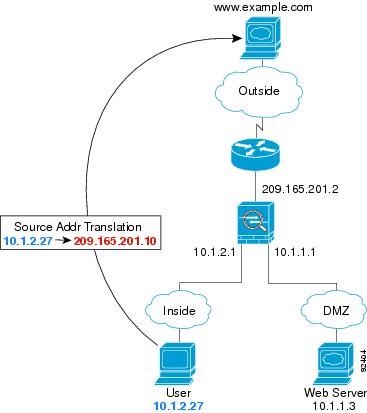
An Inside User Visits a Web Server
Figure 17-1 shows an inside user accessing an outside web server.
Figure 17-1 Inside to Outside
The following steps describe how data moves through the security appliance (see Figure 17-1):
1.
2.
For multiple context mode, the security appliance first classifies the packet according to either a unique interface or a unique destination address associated with a context; the destination address is associated by matching an address translation in a context. In this case, the interface would be unique; the www.example.com IP address does not have a current address translation in a context.
3.
The global address could be on any subnet, but routing is simplified when it is on the outside interface subnet.
4.
5.
6.
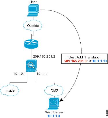
An Outside User Visits a Web Server on the DMZ
Figure 17-2 shows an outside user accessing the DMZ web server.
Figure 17-2 Outside to DMZ
The following steps describe how data moves through the security appliance (see Figure 17-2):
1.
2.
For multiple context mode, the security appliance first classifies the packet according to either a unique interface or a unique destination address associated with a context; the destination address is associated by matching an address translation in a context. In this case, the classifier "knows" that the DMZ web server address belongs to a certain context because of the server address translation.
3.
4.
5.
6.
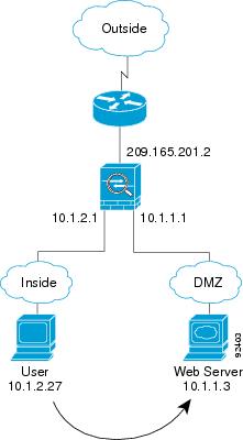
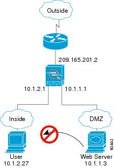
An Inside User Visits a Web Server on the DMZ
Figure 17-3 shows an inside user accessing the DMZ web server.
Figure 17-3 Inside to DMZ
The following steps describe how data moves through the security appliance (see Figure 17-3):
1.
2.
For multiple context mode, the security appliance first classifies the packet according to either a unique interface or a unique destination address associated with a context; the destination address is associated by matching an address translation in a context. In this case, the interface is unique; the web server IP address does not have a current address translation.
3.
4.
5.
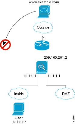
An Outside User Attempts to Access an Inside Host
Figure 17-4 shows an outside user attempting to access the inside network.
Figure 17-4 Outside to Inside
The following steps describe how data moves through the security appliance (see Figure 17-4):
1.
If the inside network uses private addresses, no outside user can reach the inside network without NAT. The outside user might attempt to reach an inside user by using an existing NAT session.
2.
3.
If the outside user is attempting to attack the inside network, the security appliance employs many technologies to determine if a packet is valid for an already established session.
A DMZ User Attempts to Access an Inside Host
Figure 17-5 shows a user in the DMZ attempting to access the inside network.
Figure 17-5 DMZ to Inside
The following steps describe how data moves through the security appliance (see Figure 17-5):
1.
2.
3.
Transparent Mode Overview
Traditionally, a firewall is a routed hop and acts as a default gateway for hosts that connect to one of its screened subnets. A transparent firewall, on the other hand, is a Layer 2 firewall that acts like a "bump in the wire," or a "stealth firewall," and is not seen as a router hop to connected devices.
This section describes transparent firewall mode, and includes the following topics:
•
•
•
•
•
•
Transparent Firewall Network
The security appliance connects the same network on its inside and outside interfaces. Because the firewall is not a routed hop, you can easily introduce a transparent firewall into an existing network.
Allowing Layer 3 Traffic
IPv4 traffic is allowed through the transparent firewall automatically from a higher security interface to a lower security interface, without an access list. ARPs are allowed through the transparent firewall in both directions without an access list. ARP traffic can be controlled by ARP inspection. For Layer 3 traffic travelling from a low to a high security interface, an extended access list is required on the low security interface. See the "Adding an Extended Access List" section for more information.
Allowed MAC Addresses
The following destination MAC addresses are allowed through the transparent firewall. Any MAC address not on this list is dropped.
•
•
•
•
•
Passing Traffic Not Allowed in Routed Mode
In routed mode, some types of traffic cannot pass through the security appliance even if you allow it in an access list. The transparent firewall, however, can allow almost any traffic through using either an extended access list (for IP traffic) or an EtherType access list (for non-IP traffic).
Note
For example, you can establish routing protocol adjacencies through a transparent firewall; you can allow OSPF, RIP, EIGRP, or BGP traffic through based on an extended access list. Likewise, protocols like HSRP or VRRP can pass through the security appliance.
Non-IP traffic (for example AppleTalk, IPX, BPDUs, and MPLS) can be configured to go through using an EtherType access list.
For features that are not directly supported on the transparent firewall, you can allow traffic to pass through so that upstream and downstream routers can support the functionality. For example, by using an extended access list, you can allow DHCP traffic (instead of the unsupported DHCP relay feature) or multicast traffic such as that created by IP/TV.
BPDU Handling
To prevent loops using the spanning tree protocol, BPDUs are passed by default. To block BPDUs, you need to configure an EtherType access list to deny them. If you are using failover, you might want to block BPDUs to prevent the switch port from going into a blocking state when the topology changes. See the "Transparent Firewall Mode Requirements" section for more information.
MAC Address vs. Route Lookups
When the security appliance runs in transparent mode, the outgoing interface of a packet is determined by performing a MAC address lookup instead of a route lookup.
Route lookups, however, are necessary for the following traffic types:
•
•
•
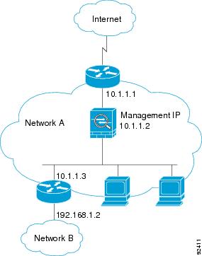
Using the Transparent Firewall in Your Network
Figure 17-6 shows a typical transparent firewall network where the outside devices are on the same subnet as the inside devices. The inside router and hosts appear to be directly connected to the outside router.
Figure 17-6 Transparent Firewall Network
Transparent Firewall Guidelines
Follow these guidelines when planning your transparent firewall network:
•
Unlike routed mode, which requires an IP address for each interface, a transparent firewall has an IP address assigned to the entire device. The security appliance uses this IP address as the source address for packets originating on the security appliance, such as system messages or AAA communications.
The management IP address must be on the same subnet as the connected network. You cannot set the subnet to a host subnet (255.255.255.255).
You can configure an IP address for the Management 0/0 management-only interface. This IP address can be on a separate subnet from the main management IP address.
Note
•
In single mode, you can only use two data interfaces (and the dedicated management interface, if available) even if your security appliance includes more than two interfaces.
Note
•
•
•
•
Unsupported Features in Transparent Mode
Table 17-1 lists the features are not supported in transparent mode.
How Data Moves Through the Transparent Firewall
Figure 17-7 shows a typical transparent firewall implementation with an inside network that contains a public web server. The security appliance has an access list so that the inside users can access Internet resources. Another access list lets the outside users access only the web server on the inside network.
Figure 17-7 Typical Transparent Firewall Data Path
This section describes how data moves through the security appliance, and includes the following topics:
•
•
•
•
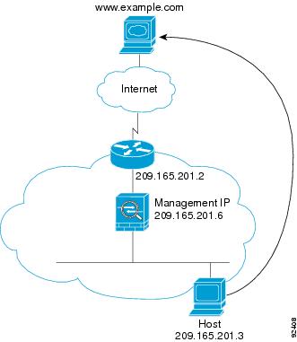
An Inside User Visits a Web Server
Figure 17-8 shows an inside user accessing an outside web server.
Figure 17-8 Inside to Outside
The following steps describe how data moves through the security appliance (see Figure 17-8):
1.
2.
For multiple context mode, the security appliance first classifies the packet according to a unique interface.
3.
4.
If the destination MAC address is not in the security appliance table, the security appliance attempts to discover the MAC address by sending an ARP request or a ping. The first packet is dropped.
5.
6.
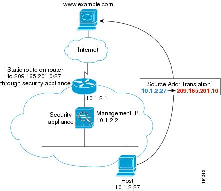
An Inside User Visits a Web Server Using NAT
Figure 17-8 shows an inside user accessing an outside web server.
Figure 17-9 Inside to Outside with NAT
The following steps describe how data moves through the security appliance (see Figure 17-8):
1.
2.
For multiple context mode, the security appliance first classifies the packet according to a unique interface.
3.
Because the mapped address is not on the same network as the outside interface, then be sure the upstream router has a static route to the mapped network that points to the security appliance.
4.
5.
If the destination MAC address is not in the security appliance table, the security appliance attempts to discover the MAC address by sending an ARP request and a ping. The first packet is dropped.
6.
7.
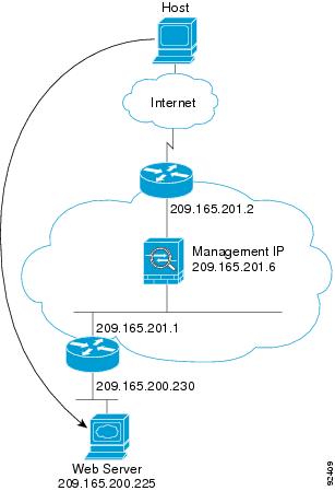
An Outside User Visits a Web Server on the Inside Network
Figure 17-10 shows an outside user accessing the inside web server.
Figure 17-10 Outside to Inside
The following steps describe how data moves through the security appliance (see Figure 17-10):
1.
2.
For multiple context mode, the security appliance first classifies the packet according to a unique interface.
3.
4.
If the destination MAC address is not in the security appliance table, the security appliance attempts to discover the MAC address by sending an ARP request and a ping. The first packet is dropped.
5.
6.
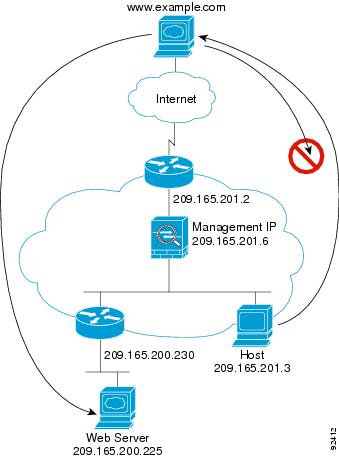
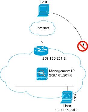
An Outside User Attempts to Access an Inside Host
Figure 17-11 shows an outside user attempting to access a host on the inside network.
Figure 17-11 Outside to Inside
The following steps describe how data moves through the security appliance (see Figure 17-11):
1.
2.
For multiple context mode, the security appliance first classifies the packet according to a unique interface.
3.
4.