-
Cisco AS5350 and Cisco AS5400 Universal Gateway Software Configuration Guide
-
Preface
-
Chap 1: Understanding Basic Hardware Architecture and Cisco IOS Software
-
Chap 2: Verifying Basic Setup
-
Chap 3: Basic Configuration Using the Command-Line Interface
-
Chap 4: Continuing Configuration Using the Command-Line Interface
-
Chap 5: Managing and Troubleshooting the Universal Port Card
-
Chap 6: Configuring Voice over IP
-
Appendix A: Using the Setup Script
-
Appendix B: ROM Monitor
-
Appendix C: Comprehensive Configuration Examples
-
 Feedback
Table Of Contents
Understanding Basic Hardware Architecture and Cisco IOS Software
Exploring the Cisco IOS File System
Upgrading to a New Cisco IOS Release
Understanding Basic Hardware Architecture and Cisco IOS Software
Note
The information herein applies to the Cisco AS5350, Cisco AS5400, and Cisco AS5400HPX universal gateways. Note that the latter requires use of Cisco IOS release 12.2(2)XB or later.
This chapter provides a brief profile of the Cisco AS5350 and Cisco AS5400 universal gateway hardware components and functionality, details how to use the Cisco IOS command-line interface (CLI), and describes how to upgrade your Cisco IOS software:
•
•
The Cisco AS5350 and Cisco AS5400 universal gateways are versatile data and voice communications platforms that provide the functions of a gateway, router, and digital modems in a single modular chassis.
The gateways are intended for Internet service providers (ISPs), telecommunications carriers, and other service providers that offer managed Internet connections, and also medium to large sites that provide both digital and analog access to users on an enterprise network.
Basic Hardware Architecture
Note
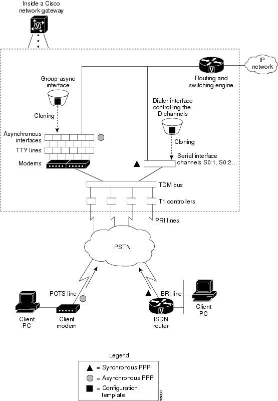
Figure 1-1 shows the logical and physical system architecture for the Cisco AS5350 and Cisco AS5400, and illustrates the components used to process a call.
Figure 1-1 Cisco AS5350 and Cisco AS5400 Basic System Architecture
Figure 1-1 shows the following:
•
•
•
•
•
•
One analog PPP call uses the following resources:
•
•
•
•
•
One synchronous PPP call uses the following resources:
•
•
Exploring the Cisco IOS File System
The Cisco IOS File System (IFS) feature provides a single interface to the following:
•
•
•
IFS first appeared in Cisco IOS Releases 11.3 AA and 12.0. For more information about IFS, refer to the chapter "Using the Cisco IOS File System" in the Cisco IOS Release 12.0 Configuration Fundamentals Configuration Guide, available online at
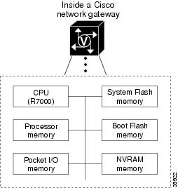
http://www.cisco.com/univercd/cc/td/doc/product/software/ios120/12cgcr/fun_c/fcprt2/fcifs.htmFigure 1-2 illustrates the memory locations and Table 1-1 describes the memory locations.
Figure 1-2 Cisco AS5350 and Cisco AS5400 Memory Locations
To inspect the file system, enter the show file systems command and the dir command as shown in the following procedure.
Step 1
Router# show file systemsFile Systems:Size(b) Free(b) Type Flags Prefixes520184 520184 nvram rw nvram:- - opaque rw null:- - opaque rw system:- - network rw tftp:- - opaque wo vfc:* 32768000 22992256 flash rw flash:7602176 4634364 flash rw bootflash:- - opaque wo lex:- - network rw rcp:- - network rw ftp:In addition, verify that you have everything that you ordered (for example, 32 megabytes of Flash memory). The asterisk (*) indicates the current directory.
Step 2
Router# dir system:Directory of system:/4 dr-x 0 <no date> memory1 -rw- 5026 <no date> running-config2 dr-x 0 <no date> ucode14 dr-x 0 <no date> vfiles
Note
Step 3
Router# dir bootflash:Directory of bootflash:/1 -rw- 1962796 Jan 01 2000 00:00:59 c5350-boot-mz.Jan72 -rw- 182684 Jun 05 2000 22:04:15 crashinfo_20000605-2204153 -rw- 172464 Jun 26 2000 19:21:04 crashinfo_20000626-1921045 -rw- 167594 Jun 26 2000 19:24:37 crashinfo_20000626-1924376 -rw- 163300 Aug 02 2000 00:14:08 crashinfo_20000802-0014087 -rw- 131250 Aug 02 2000 00:14:19 crashinfo_20000802-0014198 -rw- 158171 Aug 08 2000 23:21:40 crashinfo_20000808-2321407602176 bytes total (4634364 bytes free)In the example, the bootflash image is c5350-boot-mz.Jan7. The compressed file size is 1962796 bytes. The total Boot Flash memory size is 7602176 bytes. The number of free bytes is 4634364. The crashinfo file is a collection of useful information related to the current crash stored in Boot Flash or Flash memory.
Note
http://www.cisco.com/warp/public/63/crashinfo.html.Step 4
Router# pwdflash:Router# dir1 -rw- 9950528 Jan 01 2000 00:48:59 c5350-js-mz.121-1.XD1.bin32768000 bytes total (22817344 bytes free)The Cisco IOS image named c5350-js-mz.121-1.XD1.bin is present.Step 5
Router# dir nvram:Directory of nvram:/1 -rw- 0 <no date> startup-config2 ---- 0 <no date> private-config520184 bytes total (520184 bytes free)In the example, the startup-config and private-config are present. The private-config file is a secure file that is part of the startup configuration. It supports encryption technologies, but it is not user accessible.
Exploring Cisco IOS Software
This section describes what you need to know about the Cisco IOS software (the software that runs the gateway) before you configure the gateway using the CLI. This section includes:
Understanding these concepts saves you time if you have no or minimal experience using the Cisco IOS software.
Getting Help
Use the question mark (?) and arrow keys to help you enter commands, where Router> is the prompt for the top level of the Cisco IOS software for the Cisco AS5350 or Cisco AS5400 universal gateway.
Note
•
Router> ?•
Router> s?•
Router> show ?•
Understanding Command Modes
You need to use many different command modes to configure the gateway. Each command mode restricts you to a subset of commands.
Tip
In the following example, notice how the prompt changes after each command to indicate a new command mode:
Router> enableRouter> passwordRouter# configure terminalRouter(config)# interface fastethernet 0/0Router(config-if)# ip address 172.16.254.250Router(config-if)# exitRouter#%SYS-5-CONFIG_I: Configured from console by consoleThe last message is normal and does not indicate an error. Press Return to get the Router> prompt.
Note
Finding Command Options
This section explains how to display options for a command. To display options for a command, enter a ? at the configuration prompt, or after entering part of a command followed by a space. The configuration parser displays options available with the command. For example, if you were in global configuration mode, typed the command arap, and wanted to see all the keywords and arguments for that command, you would type arap ?
Undoing a Command or Feature
If you want to undo a command you entered or disable a feature, enter the keyword no before most commands; for example, no ip routing.
Saving Configuration Changes
Enter the copy running-config startup-config command to save your configuration changes to nonvolatile random-access memory (NVRAM) so that they are not lost if there is a system reload or power outage. For example:
Router# copy running-config startup-configBuilding configuration...It might take a minute or two to save the configuration to NVRAM. After the configuration has been saved, the following appears:
[OK]Router#
Timesaver
Timesaver
Timesaver
Timesaver
Upgrading to a New Cisco IOS Release
Obtain new Cisco IOS features and more stable code by upgrading to a new Cisco IOS release.
Step 1
Router# cd flash:Router# dirDirectory of flash:/1 -rw- 9950528 Jan 01 2000 00:48:59 c5350-js-mz.121-1.XD1.bin32768000 bytes total (13041600 bytes free)Step 2
Note
If you do not have available space, during the copy operation the system displays a message telling you to delete the current file and squeeze the flash to make room for the new image. Enter the delete flash:version command, followed by the squeeze flash command, to perform this delete-and-squeeze operation. Then proceed with the copy operation.Router# copy tftp flashAddress or name of remote host [172.22.191.135]? 172.22.191.135Source filename [c5350-js-mz.121-1.XD1.bin]? c5350-js-mz.121-3.T.binDestination filename [c5350-js-mz.121-3.T.bin]?Accessing tftp://172.22.191.135/c5350-js-mz.121-3.T.bin...Loading c5350-js-mz.121-3.T.bin from 172.22.191.135 (via FastEthernet0/0): !!!!!!!!!!!!!!!!!!!!!!!!!!!!!!!!!!!!!!!!!!!!!!!!!!!!!!!!!!!!!!!!!!!!!!!!!!!!!!!!!!!!!!!!!!!!!!!!!!!!!!!!!!!!!!!!!!!!!!!!!!!!!!!!!!!!!!!!!!!!!!!!!!!!!!!!!!!!!!!!!!!!!!!!!!!!!!!!!!!!!!!!!!!!!!!!!!!!!!!!!!!!!!!!!!!!!!!!!!!!!!!!!!!!!!!!!!!!!!!!!!!!!!!!!!!!!!!!!!!!!!!!!!!!!!!!!!!!!!!!!!!!!!!!!!!!!!!!!!!!!!!!!!!!!!!!!!!!!!!!!!!!!!!!!!!!!!!!!!!!!!!!!!!!!!!!!!!!!!!!!!!!!!!!!!!!!!!!!!!!!!!!!!!!!!![OK - 9775616/19551232 bytes]9775616 bytes copied in 66.424 secs (148115 bytes/sec)
Caution
Step 3
Router# dir flash:Directory of flash:/1 -rw- 9950528 Jan 01 2000 00:48:59 c5350-js-mz.121-1.XD1.bin2 -rw- 9775616 Jan 01 2000 00:59:10 c5350-js-mz.121-3.T.bin32768000 bytes total (13041600 bytes free)For more information on deleting the image, refer to the document Cisco IOS File System, available online at
http://www.cisco.com/univercd/cc/td/doc/product/software/ios113ed/113aa/113aa_2/allplats/ifs.htm
Note
Step 4
Router(config)# boot system flash c5350-js-mz.121-3.T.binRouter(config)# ^ZRouter# copy running-config startup-configDestination filename [startup-config]?Building configuration...[OK]To verify that this command is in effect, use the show running-configuration command. Save your running configuration before the reload so that the gateway loads the correct image.
Step 5
Router# reloadProceed with reload? [confirm]System Bootstrap, Version 12.0(20000106:234457) [tombnyg-rommon_1_6 106],SOFTWARE REV 1.6Copyright (c) 1994-2000 by cisco Systems, Inc.AS5400 platform with 131072 Kbytes of main memorySelf decompressing the image : ###################################################################################################### [OK]Self decompressing the image : #################################################################################################################################################################################################################################################################################################################################################################################################################################################### [OK]Press RETURN to get started!
Note
For more information about TFTP, refer to the document Loading and Maintaining System Images and Microcode, available online at
http://www.cisco.com/univercd/cc/td/doc/product/software/ios120/12cgcr/fun_c/fcprt2/fcimages.htm
Tip
Note
To correct a console session mismatch, do one of the following:
•
•
•
For Revision 1 motherboards, the jumper is set at motherboard pin location or row J3, where the top two pins (toward the back of the board) are jumpered. For Revision 3 motherboards, pins 1 and 2 for row J1 must be shorted out.
Changing Console Line Speed
Caution
To avoid this problem, you can do one of the following:
•
•
Log in to your Cisco AS5350 or Cisco AS5400 through the AUX port or Telnet VTY session. Enter the show running-config command and determine what speed your line console is set. Possible console speeds are 1200, 2400, 4800, 9600, 19200, 38400, 57600, and 115200. The default setting is 9600.
If your gateway is in ROM monitor mode, then the AUX port is not functioning. You must then change the terminal server port speed through your console port connection until the rommon> prompt is displayed. See Appendix B, "ROM Monitor."
Changing Gateway Line Speed
The following example shows how to configure line speed on a Cisco AS5350 or Cisco AS5400, beginning in global configuration mode:
Router(config)# line 3Router(config-line)# speed speed_valueWhere to Go Next
At this point you should go to:
•
Tip
•
•
http://www.cisco.com/univercd/cc/td/doc/product/access/acs_serv/as5400/index.htm•