-
Cisco AS5350 and Cisco AS5400 Universal Gateway Software Configuration Guide
-
Preface
-
Chap 1: Understanding Basic Hardware Architecture and Cisco IOS Software
-
Chap 2: Verifying Basic Setup
-
Chap 3: Basic Configuration Using the Command-Line Interface
-
Chap 4: Continuing Configuration Using the Command-Line Interface
-
Chap 5: Managing and Troubleshooting the Universal Port Card
-
Chap 6: Configuring Voice over IP
-
Appendix A: Using the Setup Script
-
Appendix B: ROM Monitor
-
Appendix C: Comprehensive Configuration Examples
-
 Feedback
Table Of Contents
Basic Configuration Using the Command-Line Interface
Configuring the Host Name, Password, and Time Stamps
Configuring Local AAA Security
Configuring Loopback Interfaces, Fast Ethernet Interfaces, and IP Route
Configuring the Asynchronous Group Interface
Configuring Channelized T1 and E1 Trunk Cards
Configuring a Channelized T3 Trunk Card
Request PRI Line and Switch Configuration from a Telco Service Provider
Configuring DS0 Trunk Group Dial Out
Show Trunk Group Example 2 - Trunk Group with PRI Trunks
Configuring the D Channels for ISDN Signaling
Configuring the Universal Port Card and Lines
Resetting to Default Values for Country Codes
Testing Asynchronous Shell Connections
Verifying the Final Running-Configuration
Basic Configuration Using the Command-Line Interface
Note
The information herein applies to the Cisco AS5350, Cisco AS5400, and Cisco AS5400HPX universal gateways. Note that the latter requires use of Cisco IOS release 12.2(2)XB or later.
After you have verified your basic setup, you are ready to begin configuring basic tasks that prepare your system for data call processing.
This chapter describes how to use the Cisco IOS software command-line interface (CLI) to commission your Cisco AS5350 or Cisco AS5400 universal gateway and includes the following tasks:
•
•
•
•
•
•
•
•
•
•
•
Note
Tip
http://www.cisco.com/en/US/products/hw/univgate/ps501/ps503/index.html•
http://www.cisco.com/univercd/cc/td/doc/product/access/acs_serv/as5400/index.htmYou can also view these publications on the Documentation CD-ROM that arrived with your gateway.
•
Configuring the Host Name, Password, and Time Stamps
The first configuration tasks you might want to execute are assign a host name to your Cisco AS5350 or Cisco AS5400, set an encrypted password, and turn on time stamps because:
•
•
•
Configure
Note
Verify
To verify that you configured the right host name and passwords:
•
AS5400(config)# show configurationUsing 1888 out of 512000 bytes!version XX.X..!hostname AS5400!enable secret 5 $1$60L4$X2JYOwoDc0.kqa1loO/w8/.Check the host name and encrypted password displayed near the top of the command output.
•
AS5400# exitAS5400 con0 is now availablePress RETURN to get started.AS5400> enablePassword:AS5400# show privilegeCurrent privilege level is 15AS5400#Configuring Local AAA Security
Configure authentication, authorization, and accounting (AAA) to perform login authentication by using the local username database. The login keyword authenticates EXEC shell users. Additionally, configure PPP authentication to use the local database if the session was not already authenticated by login.
AAA (called triple A) is the Cisco IOS security model used on all Cisco devices. AAA provides the primary framework through which you set up access control on the Cisco AS5350 or Cisco AS5400.
The same authentication method is used on all interfaces. AAA is set up to use the local database configured on the gateway. This local database is created with the username configuration commands.
Step 1
AS5400(config)# username admin password adminpasshereAS5400(config)# username Harry password Harrypasshere
Caution
Step 2
AS5400(config)# aaa new-modelAS5400(config)# aaa authentication login default localAS5400(config)# aaa authentication ppp default if-needed localTable 3-1 explains the previous configuration example.
Step 3
AS5400# loginUser Access VerificationUsername: adminPassword:AS5400#A successful login means that your local username works on any TTY or VTY line. Do not disconnect your session until you can log in.
Note
http://www.cisco.com/univercd/cc/td/doc/cisintwk/intsolns/aaaisg/index.htm
Creating a Login Banner
A banner shows you which unit you are connected to (or are connecting through, in the case of a console server).
Step 1
AS5400(config)# banner login |Enter TEXT message. End with the character '|'.This is a secured device.Unauthorized use is prohibited by law.|AS5400(config)# ^ZAS5400#Step 2
AS5400# loginThis is a secured device.Unauthorized use is prohibited by law.User Access VerificationUsername: adminPassword:AS5400#
Configuring Loopback Interfaces, Fast Ethernet Interfaces, and IP Route
To commission a basic dial access service perform the following tasks:
•
•
•
Step 1
AS5400(config)# interface loopback 0AS5400(config-if)# ip address 172.22.99.1 255.255.255.255AS5400(config-if)# exitAS5400(config)# interface loopback 1AS5400(config-if)# ip address 172.22.90.1 255.255.255.0AS5400(config-if)# exitAS5400(config)# interface FastEthernet 0/0AS5400(config-if)# ip address 172.28.186.55 255.255.255.240AS5400(config-if)# no shutdownAS5400(config-if)# exitAS5400(config)# ip route 0.0.0.0 0.0.0.0 172.28.186.49In this example:
•
•
Step 2
AS5400# ping 172.28.186.49Type escape sequence to abort.Sending 5, 100-byte ICMP Echos to 172.28.186.49, timeout is 2 seconds:.!!!!Success rate is 80 percent (4/5), round-trip min/avg/max = 1/1/4 msThis step verifies that you have IP connectivity with another device on the subnet. If the ping succeeds to the default gateway, try pinging the DNS server in your backbone. Make sure that the backbone routers are configured to get to the gateway; otherwise, the ping does not work. Configure the backbone routers to support the routes to the networks you are using.
Note
Configuring the Asynchronous Group Interface
Asynchronous group interfaces allow administrators to easily configure a large number of asynchronous interfaces by allowing them to clone from one managed copy. This can also reduce the number of lines in the configuration, because each individual asynchronous interface configuration can be replaced by at least one group-async. To assign the asynchronous interfaces to a group-async interface, first determine the number of asynchronous lines that need to be aggregated. This can be determined from the running configuration.
Notice that, in the "Checking the Initial Running Configuration" section on page 2-5, the asynchronous lines are numbered from 0 to 107.
Configure
Verify
To verify your group interface configuration:
•
AS5400# show interface async 4/0Async4/00 is down, line protocol is downmodem(slot/port)=4/0, state=IDLEdsx1(slot/unit/channel)=NONE, status=VDEV_STATUS_UNLOCKEDHardware is Async SerialMTU 1500 bytes, BW 115 Kbit, DLY 100000 usec,reliability 255/255, txload 1/255, rxload 1/255Encapsulation SLIP, loopback not setDTR is pulsed for 5 seconds on resetLast input never, output never, output hang neverLast clearing of "show interface" counters neverInput queue: 0/10/0/0 (size/max/drops/flushes); Total output drops: 0Queueing strategy: weighted fairOutput queue: 0/1000/64/0 (size/max total/threshold/drops)Conversations 0/1/32 (active/max active/max total)Reserved Conversations 0/0 (allocated/max allocated)Available Bandwidth 86 kilobits/sec5 minute input rate 0 bits/sec, 0 packets/sec5 minute output rate 0 bits/sec, 0 packets/sec0 packets input, 0 bytes, 0 no bufferReceived 0 broadcasts, 0 runts, 0 giants, 0 throttles0 input errors, 0 CRC, 0 frame, 0 overrun, 0 ignored, 0 abort0 packets output, 0 bytes, 0 underruns0 output errors, 0 collisions, 0 interface resets0 output buffer failures, 0 output buffers swapped out0 carrier transitions
Tip
•
AS5400# show async statusAsync protocol statistics:Int Local Remote Qd InPack OutPac Inerr Drops MTU1/00 42.1.1.1 None 0 0 0 0 0 15001/01 192.168.10.100 None 0 0 0 0 0 15001/02 192.168.10.100 None 0 0 0 0 0 15001/03 192.168.10.100 None 0 0 0 0 0 15001/04 192.168.10.100 None 0 0 0 0 0 15001/05 192.168.10.100 None 0 0 0 0 0 15004/52 192.168.10.100 None 0 0 0 0 0 1500...*6/00 192.168.10.100 34.6.42.1 0 130 50 5 0 1500*6/01 192.168.10.100 34.6.92.1 0 131 53 5 0 1500*6/02 192.168.10.100 34.5.92.1 0 130 50 5 0 1500*6/03 192.168.10.100 34.4.14.1 0 116 40 4 0 1500...*7/102 192.168.10.100 34.1.89.1 0 119 40 4 0 1500*7/103 192.168.10.100 34.4.34.1 0 118 40 4 0 1500*7/104 192.168.10.100 34.1.67.1 0 105 40 4 0 15007/105 192.168.10.100 None 0 0 0 0 0 1500*7/106 192.168.10.100 34.4.90.1 0 119 40 4 0 1500*7/107 192.168.10.100 34.1.42.1 0 119 40 4 0 1500Rcvd: 25762 packets, 1052214 bytes0 format errors, 891 checksum errors, 0 overrunSent: 8891 packets, 222264 bytes, 0 dropped
Configuring Channelized T1 and E1 Trunk Cards
On a Cisco AS5350 or Cisco AS5400, you can allocate the available channels for channelized E1 and T1 in the following ways:
•
•
•
•
•
Note
Note
Controller Numbering
The CT1/E1 controller numbering convention is dfc-slot/port in CLI commands. Trunk-card slot numbering starts from the motherboard and works up from left to right. Slot 0 is reserved for the motherboard. CT1/E1 trunk-card slots are numbered sequentially from 1 to 7. Port numbering is from 0 to 7.
Configure
Verify
To verify that your controller is up and running and no alarms have been reported:
•
AS5400# show controller t1 1/7T1 1/7 is up.No alarms detected.Framing is ESF, Line Code is B8ZS, Clock Source is Line Primary.Version info of slot 2: HW: 2, Firmware: 14, NEAT PLD: 13, NR Bus PLD: 19Data in current interval (476 seconds elapsed):0 Line Code Violations, 0 Path Code Violations0 Slip Secs, 0 Fr Loss Secs, 0 Line Err Secs, 0 Degraded Mins0 Errored Secs, 0 Bursty Err Secs, 0 Severely Err Secs, 0 Unavail SecsTotal Data (last 24 hours)0 Line Code Violations, 0 Path Code Violations,0 Slip Secs, 0 Fr Loss Secs, 0 Line Err Secs, 0 Degraded Mins,0 Errored Secs, 0 Bursty Err Secs, 0 Severely Err Secs, 0 Unavail Secs•
–
–
The TDM subsystem troubleshooting commands are not used during normal system operation. Instead, the Cisco IOS commands show the current status and settings of the TDM backplane, enable debug output for display to the user when TDM programming occurs, and provide a set of test commands to test the functionality of the TDM path. TDM commands are generally used only by a Cisco technical support representative during troubleshooting of data continuity problems.
Note
Tip
•
•
•
Configuring a Channelized T3 Trunk Card
Your AS54-DFC-CT3 trunk card offers 28 individual T1 channels (bundled in the T3) for serial transmission of data. The CT3 link supports the maintenance data link channel in C-Bit parity mode and also payload and network loopbacks. The T1s multiplexed in the CT3 link support facilities data link (FDL) in extended super frame (ESF) framing.
Additionally, you can allocate your CT1 channels as described in the "Configuring Channelized T1 and E1 Trunk Cards" section.
Controller Numbering
The CT3 controller numbering convention is dfc-slot/port in CLI commands. Trunk-card slot numbering starts from the motherboard and works up from left to right. Slot 0 is reserved for the motherboard. Trunk-card slots are numbered sequentially from 1 to 7. Port number value is always 0.
Under the CT3, the CT1 controller numbering convention is dfc-slot/port:channel in CLI commands. Port numbering values range from 1 to 28.
Configure
Verify
To verify that your controller is up and running and no alarms have been reported:
•
AS5400# show controller t3 1/0T3 1/0 is down.Applique type is Channelized T3Transmitter is sending remote alarm.Receiver has loss of signal.FEAC code received: No code is being receivedFraming is M23, Line Code is B3ZS, Clock Source is LineData in current interval (330 seconds elapsed):0 Line Code Violations, 0 P-bit Coding Violation0 C-bit Coding Violation, 0 P-bit Err Secs0 P-bit Severely Err Secs, 0 Severely Err Framing Secs0 Unavailable Secs, 0 Line Errored Secs0 C-bit Errored Secs, 0 C-bit Severely Errored SecsTotal Data (last 24 hours)9944 Line Code Violations, 0 P-bit Coding Violation,0 C-bit Coding Violation, 0 P-bit Err Secs,0 P-bit Severely Err Secs, 0 Severely Err Framing Secs,86400 Unavailable Secs, 0 Line Errored Secs,0 C-bit Errored Secs, 0 C-bit Severely Errored Secs
Tip
Configuring ISDN PRI
Your ISDN PRI interfaces are configured on the following Cisco AS5350 and Cisco AS5400 trunk cards: AS54-DFC-8CT1, AS54-DFC-8CE1 and AS54-DFC-CT3. ISDN provides out-of-band signaling using the D channel for signaling and the B channels for user data.
Channelized T1 ISDN PRI offers 23 B channels and 1 D channel. Channelized E1 ISDN PRI offers 30 B channels and 1 D channel. Channel 24 is the D channel for T1, and channel 16 is the D channel for E1.
For a complete description of the commands mentioned in this chapter, refer to the Dial Technologies Command Reference, available online at
http://www.cisco.com/univercd/cc/td/doc/product/software/ios122/122cgcr/index.htm.Request PRI Line and Switch Configuration from a Telco Service Provider
Before configuring ISDN PRI on your Cisco router, you need to order a correctly provisioned ISDN PRI line from your telecommunications service provider.
This process varies from provider to provider on a national and international basis. However, some general guidelines follow:
•
•
•
Table 3-2 provides a sample of the CT1 configuration attributes you might request for a PRI switch.
Controller Numbering
The CT1/E1 controller numbering convention is dfc-slot/port in CLI commands. Trunk-card slot numbering starts from the motherboard and works up from left to right. Slot 0 is reserved for the motherboard. CT1/E1 trunk-card slots are numbered sequentially from 1 to 7. Port numbering is from 0 to 7.
The CT3 controller numbering convention is dfc-slot/port in CLI commands. Trunk-card slot numbering starts from the motherboard and works up from left to right. Slot 0 is reserved for the motherboard. Trunk-card slots are numbered sequentially from 1 to 7. Port number value is always 0.
Under the CT3, the CT1 controller numbering convention is dfc-slot/port:channel in CLI commands. Port numbering values range from 1 to 28.
Configure
Step 1
Enters enable mode. Enters the password. You are in enable mode when the prompt changes to AS5350# or AS5400#.
Step 2
Enters global configuration mode. You are in global configuration mode when the prompt changes to AS5350(config)# or AS5400(config)#.
Step 3
Selects a service provider switch type that accommodates PRI. (Refer to Table 3-3 for a list of supported switch type keywords.)
Step 4
Specifies T1 controller dfc-slot, port number, and channel. On the CT3 trunk card, port-number values range from 1 to 28. On the CT1 trunk card, port-number values range from 0 to 7.
or
Specifies E1 controller dfc-slot, port number, and channel. On the CE1 trunk card, port number values range from 0 to 7.
Note
Step 5
Enters framing type for the CT3 or CT1 trunk card.
or
Enters framing type for the CE1 trunk card.Step 6
AS5400(config-controller)# linecode b8zsorAS5400(config-controller)# linecode hdb3Defines the line code as binary 8 zero substitution (B8ZS) for the CT3 or CT1 trunk card.
or
Defines the line code as high-density bipolar 3 (HDB3) for the CE1 trunk card.Step 7
Configures ISDN PRI.
If you do not specify the timeslots, the controller is configured for 23 B channels and 1 D channel.
Step 8
Returns to enable mode.
1 On CT1, timeslots range 1 to 24. You can specify a range of timeslots (for example, pri-group timeslots 12-24) if other timeslots are used for non-PRI channel groups.
For CT1 ISDN PRI—If you do not specify the timeslots, the specified controller is configured for 23 B channels and 1 D channel. B channel numbers range 1 to 23; channel 24 is the D channel for T1. Corresponding serial interface numbers range 0 to 23. In commands, the D channel is interface serial slot/port:23—for example, interface serial 1/0:23.
For CE1 ISDN PRI—If you do not specify the timeslots, the specified controller is configured for 30 B channels and 1 D channel. B channel numbers range 1 to 31; channel 16 is the D channel for E1. Corresponding serial interface numbers range 0 to 30. In commands, the D channel is interface serial slot/port:15—for example, interface serial 1/0:15.
Verify
To verify that you have configured the interfaces correctly:
•
AS5400# show controller t3 1/0T3 1/0 is up.Applique type is Channelized T3No alarms detected.MDL transmission is disabledFEAC code received:No code is being receivedFraming is C-BIT Parity, Line Code is B3ZS, Clock Source is InternalData in current interval (270 seconds elapsed):0 Line Code Violations, 0 P-bit Coding Violation0 C-bit Coding Violation, 0 P-bit Err Secs0 P-bit Severely Err Secs, 0 Severely Err Framing Secs0 Unavailable Secs, 0 Line Errored Secs0 C-bit Errored Secs, 0 C-bit Severely Errored SecsTotal Data (last 32 15 minute intervals):0 Line Code Violations, 0 P-bit Coding Violation,0 C-bit Coding Violation, 0 P-bit Err Secs,0 P-bit Severely Err Secs, 0 Severely Err Framing Secs,0 Unavailable Secs, 0 Line Errored Secs,0 C-bit Errored Secs, 0 C-bit Severely Errored Secs•
AS5400# show controller t1 1/0T1 1/0 is up.Applique type is Channelized T1Cablelength is long gain36 0dbNo alarms detected.alarm-trigger is not setVersion info of slot 1: HW:768, PLD Rev:4Framer Version:0x8Manufacture Cookie Info:EEPROM Type 0x0001, EEPROM Version 0x01, Board ID 0x041,Board Hardware Version 3.0, Item Number 73-4089-03,Board Revision 05, Serial Number JAB99432626,PLD/ISP Version 0.1, Manufacture Date 11-Nov-1999.Framing is ESF, Line Code is B8ZS, Clock Source is Line.Data in current interval (264 seconds elapsed):3 Line Code Violations, 1 Path Code Violations5 Slip Secs, 0 Fr Loss Secs, 1 Line Err Secs, 1 Degraded Mins5 Errored Secs, 0 Bursty Err Secs, 0 Severely Err Secs, 0 Unavail Secs...•
AS5400# show isdn statusGlobal ISDN Switchtype = primary-5essISDN Serial1/0:1:23 interfacedsl 0, interface ISDN Switchtype = primary-5essLayer 1 Status:ACTIVELayer 2 Status:TEI = 0, Ces = 1, SAPI = 0, State = MULTIPLE_FRAME_ESTABLISHEDLayer 3 Status:0 Active Layer 3 Call(s)Activated dsl 0 CCBs = 0The Free Channel Mask: 0x807FFFFF...ISDN Serial1/0:28:23 interfacedsl 27, interface ISDN Switchtype = primary-5essLayer 1 Status:ACTIVELayer 2 Status:TEI = 0, Ces = 1, SAPI = 0, State = MULTIPLE_FRAME_ESTABLISHEDLayer 3 Status:0 Active Layer 3 Call(s)Activated dsl 27 CCBs = 0The Free Channel Mask: 0x807FFFFFTotal Allocated ISDN CCBs = 0Note the following information for Serial 1/0:1:23 (the first half of the messages):
–
–
–
–
•
AS5400# show isdn servicePRI Channel Statistics:ISDN Se0:23, Channel (1-31)Activated dsl 0State (0=Idle 1=Propose 2=Busy 3=Reserved 4=Restart 5=Maint)2 2 2 2 2 2 2 2 2 2 2 2 2 2 2 2 2 2 2 0 0 0 0 3 3 3 3 3 3 3 3Channel (1-31) Service (0=Inservice 1=Maint 2=Outofservice)0 0 0 0 0 0 0 0 0 0 0 0 0 0 0 0 0 0 0 0 0 0 0 2 2 2 2 2 2 2 2ISDN Se1:23, Channel (1-31)Activated dsl 1State (0=Idle 1=Propose 2=Busy 3=Reserved 4=Restart 5=Maint)2 2 2 2 2 2 2 2 2 2 2 2 2 2 2 2 2 2 2 2 2 2 0 3 3 3 3 3 3 3 3Channel (1-31) Service (0=Inservice 1=Maint 2=Outofservice)0 0 0 0 0 0 0 0 0 0 0 0 0 0 0 0 0 0 0 0 0 0 0 2 2 2 2 2 2 2 2ISDN Se2:23, Channel (1-31)Activated dsl 2State (0=Idle 1=Propose 2=Busy 3=Reserved 4=Restart 5=Maint)2 2 2 2 2 2 2 2 2 2 2 2 2 2 2 2 2 2 2 0 0 0 0 3 3 3 3 3 3 3 3Channel (1-31) Service (0=Inservice 1=Maint 2=Outofservice)0 0 0 0 0 0 0 0 0 0 0 0 0 0 0 0 0 0 0 0 0 0 0 2 2 2 2 2 2 2 2ISDN Se3:23, Channel (1-31)Activated dsl 3State (0=Idle 1=Propose 2=Busy 3=Reserved 4=Restart 5=Maint)2 2 2 2 2 2 2 2 2 2 2 2 2 2 2 2 2 2 2 2 2 2 2 3 3 3 3 3 3 3 3Channel (1-31) Service (0=Inservice 1=Maint 2=Outofservice)0 0 0 0 0 0 0 0 0 0 0 0 0 0 0 0 0 0 0 0 0 0 0 2 2 2 2 2 2 2 2ISDN Se4:23, Channel (1-31)Activated dsl 4State (0=Idle 1=Propose 2=Busy 3=Reserved 4=Restart 5=Maint)2 2 2 2 2 2 2 2 2 2 2 2 2 2 2 2 2 2 2 2 2 2 2 3 3 3 3 3 3 3 3Channel (1-31) Service (0=Inservice 1=Maint 2=Outofservice)0 0 0 0 0 0 0 0 0 0 0 0 0 0 0 0 0 0 0 0 0 0 0 2 2 2 2 2 2 2 2ISDN Se5:23, Channel (1-31)Activated dsl 5State (0=Idle 1=Propose 2=Busy 3=Reserved 4=Restart 5=Maint)2 2 2 2 2 2 2 2 2 2 2 2 0 0 0 0 0 0 0 0 0 0 0 3 3 3 3 3 3 3 3Channel (1-31) Service (0=Inservice 1=Maint 2=Outofservice)0 0 0 0 0 0 0 0 0 0 0 0 0 0 0 0 0 0 0 0 0 0 0 2 2 2 2 2 2 2 2ISDN Se6:23, Channel (1-31)Activated dsl 6State (0=Idle 1=Propose 2=Busy 3=Reserved 4=Restart 5=Maint)2 2 2 2 2 2 2 2 2 2 2 2 2 2 2 2 2 2 2 2 2 2 0 3 3 3 3 3 3 3 3Channel (1-31) Service (0=Inservice 1=Maint 2=Outofservice)0 0 0 0 0 0 0 0 0 0 0 0 0 0 0 0 0 0 0 0 0 0 0 2 2 2 2 2 2 2 2ISDN Se7:23, Channel (1-31)Activated dsl 7State (0=Idle 1=Propose 2=Busy 3=Reserved 4=Restart 5=Maint)2 2 2 2 2 2 2 2 2 2 2 2 2 2 2 2 2 2 2 2 2 2 0 3 3 3 3 3 3 3 3Channel (1-31) Service (0=Inservice 1=Maint 2=Outofservice)0 0 0 0 0 0 0 0 0 0 0 0 0 0 0 0 0 0 0 0 0 0 0 2 2 2 2 2 2 2 2
Note
In the following show running-config example, six CT1s are configured into channel-groups:
AS5400# show running-configBuilding configuration...Current configuration:!! Last configuration change at 15:49:30 UTC Mon Apr 3 2000 by admin! NVRAM config last updated at 01:35:05 UTC Fri Mar 17 2000 by admin!version 12.0service timestamps debug datetime msec localtime show-timezoneservice timestamps log datetime msec localtime show-timezoneservice password-encryption!---text omitted---!controller T3 1/0framing m23clock source linet1 1-28 controller!controller T1 1/0:11framing esfchannel-group 20 timeslots 1-24 speed 64!controller T1 1/0:12framing esfchannel-group 20 timeslots 1-24 speed 64!controller T1 1/0:13framing esfchannel-group 20 timeslots 1-24 speed 64!controller T1 1/0:14framing esfchannel-group 20 timeslots 1-24 speed 64!controller T1 1/0:15framing esfchannel-group 20 timeslots 1-24 speed 64!controller T1 1/0:16framing esfchannel-group 20 timeslots 1-24 speed 64
Tip
•
•
Configuring DS0 Trunk Group Dial Out
The DS0 Trunk Group Dial Out feature adds functionality that enhances outbound call routing by giving the user control over individual DS0s for outbound calls. Previous to this feature, outbound DS0s could not be configured separately from DS1s. The dial out capabilities of a DS1 applied to all DS0s under that DS1.
Currently, the aggregation of DS1s into trunk groups is done via the Trunk Group Resource Manager (TGRM). The DS0 Trunk Group Dial Out feature enables the TGRM subsystem to aggregate DS0s into trunk groups also. The dial out capabilities of these DS0 trunk groups can then be configured directly at the DS0 level, via the TGRM CLI and by setting the Authentication Authorization and Accounting (AAA) attributes.
The configuration of DS0s for outbound calls enables the Dial on Demand feature to initiate outbound calls over a set of B channels.
DS0 Dial Out Trunk Groups are configured on a Network Access Server (NAS). They support both digital and asynchronous calls and can be configured for the following types of circuits.
•
–
–
A trunk group is a logical grouping of multiple T1/E1 interfaces with the same signaling characteristics. A single trunk group can contain up to 64 trunks. Each trunk group can consist of DS0s from different circuits, but each individual DS0 can belong to only one trunk group. Trunk groups configured for ISDN can consist of both PRI and NFAS interfaces.
Note
Note
Trunk Group Resource Manager
The Trunk Group Resource Manager (TGRM) supports the logical grouping, configuration, and joint management of one or more interfaces. The TGRM is used to store configuration information and to accept or select an interface from a trunk group when requested.
A trunk group is provisioned as the target of a dial peer or a dial out profile on an AAA server, and the TGRM transparently selects the specific interface and channels to use for incoming or outgoing calls. Trunks are selected based on the trunk that is least used (default configuration) or the hunt-scheme configured.
Using trunk groups simplifies the task of configuring dial peers and interfaces, and also enables the dynamic selection of interfaces as needed in the access server.
A trunk group can include any number of interfaces, but all the interfaces in a trunk group must use the same type of signaling.
The TGRM subsystem has been enhanced to add fractional trunks to a trunk group. A fractional trunk is a single DS0 or a group of DS0s from a trunk.
Configure
The trunk-group command assigns a trunk to a trunk group by specifying the trunk group label parameter and optionally setting the preference parameter.
The DS0 Dial Out Trunk Group feature adds two new optional keywords:
•
•
The timeslots keyword allows you to selectively add DS0s from a signaling circuit. Fractional trunk-groups are configured from the controller configuration mode only (as a PRI serial interface may represent multiple member interfaces, including NFAS). If the timeslots option is not specified, all the DS0s in the signaling circuit are assigned to the trunk-group.
The preference keyword is configured after the timeslots option and is visible only when the timeslots option is used. This helps to differentiate between the list of timeslots number and the preference number.
The following example shows the syntax for configuring selected DS0s using the timeslots keyword and the preference keyword.
trunk-group <label> timeslot <list of timeslots> preference <preference>The following example shows the syntax for configuring all the DS0s in the signaling circuit:
trunk-group <label> <preference>Syntax Parameter Descriptions
The following examples show the configuration steps for PRI signalling. Controller T1 3 is a trunk configured for PRI.
PRI Trunk Configuration
Step 1
AS5400(config)#controller T1 3AS5400(config-controller)#framing esfAS5400(config-controller)#clock source line secondary 3AS5400(config-controller)#linecode b8zsAS5400(config-controller)#pri-group timeslots 1-24AS5400(config-controller)#!Step 2
AS5400(config)#interface Serial3:23AS5400(config-if)#no ip addressAS5400(config-if)#trunk-group PRI-TRUNK-GROUP
Note
Step 3
AS5400(config)#controller T1 3AS5400(config-controller)#framing esfAS5400(config-controller)#clock source line secondary 3AS5400(config-controller)#linecode b8zsAS5400(config-controller)#pri-group timeslots 1-24AS5400(config-controller)#trunk-group PRI-TRUNK-GROUP-1 timeslots 1-10AS5400(config-controller)#trunk-group PRI-TRUNK-GROUP-2 timeslots 11-15AS5400(config-controller)#trunk-group PRI-TRUNK-GROUP-3 timeslots 20-22 preference 10
Note
Verify
The show trunk group command displays the DS0s that belong to a particular trunk group.
A trunk-group can be a group of DS0s from various signaling channels.Show Trunk Group Example 2 - Trunk Group with PRI Trunks
AS5400#show trunk group pri-tgTrunk group: pri-tgDescription:trunk group label: pri-tgTranslation profile (Incoming):Translation profile (Outgoing):Hunt Scheme is least-usedMax Calls (Incoming): NOT-SET (Any) NOT-SET (Voice) NOT-SET (Data)Max Calls (Outgoing): NOT-SET (Any) NOT-SET (Voice) NOT-SET (Data)Retries: 0Trunk 2/1:23 Preference 10Channels : 1-23Total channels available : 23Data = 0, Voice = 0, Modem = 0, Pending = 0, Free = 23Total calls for trunk group: Data = 0, Voice = 0, Modem = 0Pend = 0, Free = 23advertise_flag 0x00000040, capacity timer 25 sec tripl_config_mask 0x00000000AC_curr 24, FD_curr 0, SD_curr 0succ_curr 0 tot_curr 0succ_report 0 tot_report 0changed 0 replacement position 0Configuring the D Channels for ISDN Signaling
The ISDN D channels carry the control and signaling information for your ISDN calls—for both circuit-switched data calls, and analog modem calls.
The D channel notifies the central office switch to send the incoming call to particular timeslots on the Cisco gateway or router. Each one of the B channels carries data or voice. The D channel carries signaling for the B channels. The D channel identifies if the call is a circuit switched digital call or an analog modem call. Analog modem calls are decoded and then get sent off to the onboard modems. Circuit-switched digital calls are directly relayed off to the ISDN processor in the gateway.
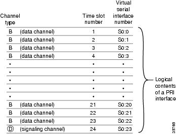
When you configured your ISDN PRI on the CT1 or CE1 controller, you automatically created a serial interface that corresponds to the PRI group timeslots. This interface is a logical entity that is associated with the specific controller. After the serial interface is created, you must configure the D channel serial interface that carries signaling. The configuration applies to all the PRI B channels (timeslots) for that pri group.
Figure 3-1 shows the logical contents of a ISDN PRI interface used in a T1 network configuration. The logical contents includes 23 B channels, one D channel, 24 timeslots, and 24 virtual serial interfaces (total number of Bs + D).
Note
Figure 3-1 Logical Relationship of ISDN PRI Components for T1
Note
Configure
Verify
To verify your D channel configuration:
•
AS5400# show interface serial 1/0:23Serial1/0:23 is up, line protocol is up (spoofing)Hardware is DSX1Internet address is 172.16.254.254/16MTU 1500 bytes, BW 64 Kbit, DLY 20000 usec,reliability 255/255, txload 1/255, rxload 1/255Encapsulation PPP, loopback not setLast input 00:00:03, output never, output hang neverLast clearing of "show interface" counters 00:00:01Queueing strategy:fifoOutput queue 0/40, 0 drops; input queue 0/75, 0 drops1 minute input rate 0 bits/sec, 0 packets/sec1 minute output rate 0 bits/sec, 0 packets/sec0 packets input, 0 bytes, 0 no bufferReceived 0 broadcasts, 0 runts, 0 giants, 0 throttles0 input errors, 0 CRC, 0 frame, 0 overrun, 0 ignored, 0 abort0 packets output, 0 bytes, 0 underruns0 output errors, 0 collisions, 0 interface resets0 output buffer failures, 0 output buffers swapped out0 carrier transitionsTimeslot(s) Used:24, Transmitter delay is 0 flagsAS5400#
Tip
•
•
AS5400# show interface serial 1/0:23Serial1/0:23 is up, line protocol is up (spoofing)Hardware is DSX1Internet address is 172.16.254.254/16MTU 1500 bytes, BW 64 Kbit, DLY 20000 usec,reliability 255/255, txload 1/255, rxload 1/255Encapsulation PPP, loopback not setLast input 00:00:07, output never, output hang neverLast clearing of "show interface" counters 00:00:06Queueing strategy:fifoOutput queue 0/40, 0 drops; input queue 0/75, 0 drops1 minute input rate 0 bits/sec, 0 packets/sec1 minute output rate 0 bits/sec, 0 packets/sec0 packets input, 0 bytes, 0 no bufferReceived 0 broadcasts, 0 runts, 0 giants, 0 throttles0 input errors, 0 CRC, 0 frame, 0 overrun, 0 ignored, 0 abort0 packets output, 0 bytes, 0 underruns0 output errors, 0 collisions, 0 interface resets0 output buffer failures, 0 output buffers swapped out0 carrier transitionsTimeslot(s) Used:24, Transmitter delay is 0 flagsAS5400#
Configuring the Universal Port Card and Lines
Rather than the more traditional line/modem one-to-one correspondence, lines are mapped to a Service Process Element (SPE) that resides on the universal port card. Associated SPE firmware serves a function similar to modem code on a MICA modem.
One SPE provides services for multiple ports. Busyout and shutdown can be configured at the SPE or port level. There are several universal port cards, each with a different number or ports, available for the Cisco AS5350 and Cisco AS5400.
The universal port card performs the following functions:
•
•
•
Note
For detailed information about CLI commands supported on the universal port card, refer to Monitoring Voice and Fax Services on the Cisco AS5400 Universal Gateway, available online at
http://www.cisco.com/univercd/cc/td/doc/product/software/. Select your Cisco IOS release and search for this title.
SPE Firmware
SPE firmware is automatically downloaded to a universal port card from the Cisco AS5350 or Cisco AS5400 when you boot the system for the first time or when you insert a universal port card while the system is operating. When you insert cards while the system is operating, the Cisco IOS image recognizes the cards and downloads the required firmware to the cards.
The SPE firmware image is bundled with the gateway Cisco IOS image. The SPE firmware image uses an auto detect mechanism, which enables the universal port card to service multiple call types. An SPE detects the call type and automatically configures itself for that operation. The firmware is upgradable independent of Cisco IOS upgrades, and different firmware versions can be configured to run on SPEs in the same card.
The universal port card supports the modem standards and features listed in Table 3-4.
Configure
Configure the lines and ports to allow users to dial in to your network.
Modems and lines are configured after:
•
•
Each modem is mapped to a dedicated asynchronous line inside the gateway. After the modem inout command is applied to the lines, the gateway is ready to accept modem calls.
AAA security is applied to the lines by the aaa new-model command and aaa authentication login default local command. AAA performs login authentication by using the local username database. The login keyword authenticates EXEC shell users. For more information about the AAA commands, see the "Configuring Local AAA Security" section.
Note
Resetting to Default Values for Country Codes
To reset to default settings for country codes, enter the following commands in global configuration mode:
•
Verify
To verify your SPE configuration:
•
AS5400# show speSPE settings:==============Country code configuration: default T1 (u Law)Polling interval: 8 secs.History log events: 50(per port)Port legends:============Port state: (s)shutdown (t)test (r)recovery (d)download(b)busiedout (p)busyout pending, (B)bad (a)active callCall type: (m)modem (d)digital (f)fax-relay (v)voice (_)not in useSystem resources summary:======================Total ports: 108, in use ports: 0, disabled ports: 0, free ports: 108Total active calls: modem 0, voice 0, digital 0, fax-relay 0SPE SPE SPE SPE Port CallSPE# Port # State Busyout Shut Crash State Type4/00 0000-0005 ACTIVE 0 0 0 ______ ______4/01 0006-0011 ACTIVE 0 0 0 ______ ______4/02 0012-0017 ACTIVE 0 0 0 ______ ______4/03 0018-0023 ACTIVE 0 0 0 ______ ______4/04 0024-0029 ACTIVE 0 0 0 ______ ______...•
AS5400# show line 1Tty Typ Tx/Rx A Modem Roty AccO AccI Uses Noise Overruns Int1 AUX 9600/9600 - - - - - 0 0 0/0 -ReadyLine 1, Location: "", Type: ""Length: 24 lines, Width: 80 columnsBaud rate (TX/RX) is 9600/9600, no parity, 2 stopbits, 8 databitsStatus: ReadyCapabilities: noneModem state: ReadyGroup codes: 0Modem hardware state: noCTS noDSR DTR RTSTTY NUMBER 1Parity Error = 0 Framing Error = 0 Receive Error = 0 Overrun = 0Outcount = 0 totalout = 39 incount = 0 totalin = 0Special Chars: Escape Hold Stop Start Disconnect Activation^^x none - - noneTimeouts: Idle EXEC Idle Session Modem Answer Session Dispatch00:10:00 never none not setIdle Session Disconnect WarningneverLogin-sequence User Response
Tip
Configuring Clocking
The time-division multiplexing (TDM) bus on the Cisco AS5350 and Cisco AS5400 backplane can receive an input clock from one of four basic sources on the gateway:
•
•
•
Note
Trunk-Card Ports
The TDM bus can be synchronized with any trunk cards. On the CT1/CE1 trunk card, each port receives the clock from the T1/E1 line. The CT3 trunk card uses an M13 multiplexer to receive the DS1 clock. Each port on each trunk-card slot has a default clock priority. Also, clock priority is configurable through the dial-tdm-clock priority CLI command.
External Clock
The TDM bus can be synchronized with an external clock source that can be used as an additional network reference. If no clocks are configured, the system uses a primary clock through a software-controlled default algorithm. If you want the external T1/E1 clock (via the BITs interface) as the primary clock source, you must configure it using the dial-tdm-clock priority CLI command; the external clock is never selected by default.
The BITs interface requires a T1 line composite clock reference set at 1.544 MHz and an E1 line composite clock reference set at 2.048 MHz.
Free-Running Clock
If there is no good clocking source from a trunk card or an external clock source, then select the free-running clock from the local oscillator through the dial-tdm-clock priority CLI command.
The following table lists commands to help you configure the clock source and clock source priority used by the TDM bus:
Configuration Examples
In the following example, BITS clock is set at priority 1.
AS5400(config)# dial-tdm-clock priority 1 externalAS5400(config)# exitAS5400#In the following example, a trunk clock from an CT1 trunk card is set at priority 2 and uses slot 4 and ds1 port (controller) 6.
AS5400(config)# dial-tdm-clock priority 2 4/6AS5400(config)# exitIn the following example, a trunk clock from a CT3 trunk card is set at priority 2 and uses slot 1, ds3 port 0, and ds1 port 19.
AS5400(config)# dial-tdm-clock priority 2 1/0:19AS5400(config)# exitIn the following example, free-running clock is set at priority 3.
AS5400(config)# dial-tdm-clock priority 3 freeAS5400(config)# exitVerify
You can verify the system primary and backup clocks, status of all trunk-card controller clocks, and information about and history of last 20 TDM clock changes and the events that caused them.
•
AS5400# show tdm clocksPrimary Clock:--------------TDM Bus Master Clock Generator State = HOLDOVERBackup clocks for primary:Source Slot Port DS3-Port Priority Status State-------------------------------------------------------------Trunk cards controllers clock health information------------------------------------------------Slot Type 7 6 5 4 3 2 1 01 T1 B B B B B B B BCLOCK CHANGE HISTORY--------------------------CLOCK Event Time----- ----- ----1/1 Loss Of Signal (LOS) 00:00:22 UTC Tue Nov 30 19991/2 Loss Of Signal (LOS) 00:00:22 UTC Tue Nov 30 19991/3 Alarm Indication Signal (AIS) 00:00:22 UTC Tue Nov 30 19991/4 Alarm Indication Signal (AIS) 00:00:22 UTC Tue Nov 30 19991/5 Alarm Indication Signal (AIS) 00:00:22 UTC Tue Nov 30 19991/6 Alarm Indication Signal (AIS) 00:00:22 UTC Tue Nov 30 19991/7 Alarm Indication Signal (AIS) 00:00:22 UTC Tue Nov 30 1999AS5400#•
AS5400# show tdm clocksPrimary Clock:--------------System primary is slot 7 ds3_port 0 ds1_port 1 of priority 1TDM Bus Master Clock Generator State = NORMALBackup clocks for primary:Source Slot Port DS3-Port Priority Status State-------------------------------------------------------------Trunk 7 8 YES 214 Good DefaultTrunk 7 9 YES 215 Good DefaultTrunk cards controllers clock health information------------------------------------------------CT3 2 2 2 2 2 2 2 2 2 1 1 1 1 1 1 1 1 1 1Slot Port Type 8 7 6 5 4 3 2 1 0 9 8 7 6 5 4 3 2 1 0 9 8 7 6 5 4 3 2 17 0 T3 G G G G G G G G G G G G G G G G G G G G G G G G G G G GCLOCK CHANGE HISTORY--------------------------CLOCK Event Time----- ----- ----7/1 Signal recovered from LOS 00:03:29 UTC Sat Jan 1 20007/8 Alarm Indication Signal (AIS) 11:27:48 UTC Fri Feb 25 20007/1 Signal recovered from LOS 11:30:22 UTC Fri Feb 25 2000AS5400#•
AS5400# show tdm clocksPrimary Clock:System primary is slot 2 port 0 of priority 15TDM Bus Master Clock Generator State = NORMALBackup clocks for primary:Source Slot Port DS3-Port Priority Status StateTrunk 2 1 NO 205 Good DefaultTrunk cards controllers clock health informationSlot Type 7 6 5 4 3 2 1 02 T1 B B B B G G G GCLOCK CHANGE HISTORYCLOCK Event Time2/1 Controller shutdown 23:23:06 UTC Tue Nov 30 19992/0 Change in CLI configuration 23:27:25 UTC Tue Nov 30 1999AS5400#•
AS5400# show tdm clocksPrimary Clock:System primary is FREE RUNNING with priority 2TDM Bus Master Clock Generator State = FREERUNBackup clocks for primary:Source Slot Port DS3-Port Priority Status StateTrunk 2 0 NO 204 Good DefaultTrunk 2 1 NO 205 Good DefaultTrunk cards controllers clock health informationSlot Type 7 6 5 4 3 2 1 02 T1 B B B B G G G GCLOCK CHANGE HISTORYCLOCK Event TimeFreerun Change in CLI configuration 23:27:25 UTC Tue Nov 30 1999AS5400#•
AS5400# show tdm clocksPrimary Clock:System primary is external with priority 1TDM Bus Master Clock Generator State = NORMALBackup clocks for primary:Source Slot Port DS3-Port Priority Status StateTrunk 2 0 NO 204 Good DefaultTrunk 2 1 NO 205 Good DefaultTrunk cards controllers clock health informationSlot Type 7 6 5 4 3 2 1 02 T1 B B B B G G G GCLOCK CHANGE HISTORYCLOCK Event TimeExternal Change in CLI configuration 23:27:25 UTC Tue Nov 30 1999AS5400#
Tip
Enabling IP Basic Setup
Fine-tune the IP routing functions and domain-name services for EXEC shell users, by performing the following steps:
Step 1
AS5400(config)# ip subnet-zeroAS5400(config)# no ip source-routeAS5400(config)# ip classlessAS5400(config)# ip domain-lookupTable 3-5 describes the commands in the example.
Step 2
AS5400(config)# ip host mymap 172.22.53.101AS5400(config)# ip domain-name mydomain.comAS5400(config)# ip name-server 172.22.11.10AS5400(config)# ip name-server 172.22.11.11Table 3-6 describes the commands in the example.
Testing Asynchronous Shell Connections
This task verifies that the following components are working:
•
•
•
The Cisco IOS software provides a command-line interface (CLI) called the EXEC. The EXEC:
•
•
–
–
–
–
During this task, some administrators try to make complex services function, such as PPP-based Web browsing. Do not jump ahead. Many other elements still must be configured (for example, PPP and IPCP). The asynchronous-shell test ensures that the EXEC's login prompt can be accessed by a client modem. Taking a layered approach to building a network isolates problems and saves you time.
To test asynchronous-shell connections, perform the following steps:
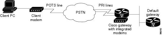
Step 1
Figure 3-2 Test Environment
Step 2
atOK
Note
http://www.cisco.com/pcgi-bin/Support/PSP/psp_view.pl?p=Internetworking:ASYNC&s=Implementation_and_ConfigurationStep 3
atdt 5554100CONNECT 33600/REL - LAPM
Note
Step 4
This is a secured device.Unauthorized use is prohibited by law.User Access VerificationUsername: HarryPassword:AS5400>Step 5
AS5400# show callerActive IdleLine User Service Time Timecon 0 admin TTY 00:39:09 00:00:00tty 216 Harry TTY 00:00:30 00:00:07AS5400# show caller user HarryUser: Harry, line tty 216, service TTYActive time 00:00:42, Idle time 00:00:19Timeouts: Absolute Idle IdleSession ExecLimits: - - 00:10:00Disconnect in: - - 00:09:40TTY: Line 1/00DS0: (slot/unit/channel)=2/0/18Line: Baud rate (TX/RX) is 115200/115200, no parity, 1 stopbits, 8 databitsStatus: Ready, Active, No Exit BannerCapabilities: No Flush-at-Activation, Hardware Flowcontrol InHardware Flowcontrol Out, Modem Callout, Modem RI is CDIntegrated ModemModem State: Ready
Note
Step 6
AS5400# telnet 171.68.186.49Trying 171.68.186.49 ... Openaccess-gw line 2access-gw telnet smartTranslating "smart"...domain server (171.68.10.70) [OK]Trying smart.cisco.com (171.68.191.135)... OpenUNIX(r) System V Release 4.0 (smart)login: RouterPassword:No directory! Logging in with home=/Last login: Fri Aug 18 13:50:07 from dhcp-aus-163-230Sun Microsystems Inc. SunOS 5.5.1 Generic May 1996
Verifying the Final Running-Configuration
The following is an example of a final running configuration:
AS5400# show running-configBuilding configuration...Current configuration : 6017 bytes!version 12.2no service single-slot-reload-enableno service padservice timestamps debug uptimeservice timestamps log uptimeno service password-encryption!hostname AS5400!boot system tftp c5350-js-mz.xm.Feb19 171.69.20.20no boot startup-testno logging bufferedlogging rate-limit console 10 except errorsenable secret 5 $1$ltzj$8lGJ1cGmyZRdXdPXncLAo/!!resource-pool disable!!voice-fastpath enableip subnet-zerono ip fingerip domain-name cisco.comip name-server 171.69.11.48ip name-server 171.69.2.132ip name-server 171.69.2.133!no ip dhcp-client network-discovery!!fax interface-type modemmta receive maximum-recipients 0!!crypto mib ipsec flowmib history tunnel size 200crypto mib ipsec flowmib history failure size 200!!controller T1 1/0framing sflinecode ami!controller T1 1/1framing sflinecode ami!...controller T1 1/7framing sflinecode ami!!interface FastEthernet0/0ip address 172.21.101.21 255.255.255.0no ip route-cacheno ip mroute-cacheduplex autospeed auto!interface FastEthernet0/1no ip addressno ip route-cacheno ip mroute-cacheshutdownduplex autospeed auto!interface Serial0/0no ip addressno ip route-cacheno ip mroute-cacheshutdownclockrate 2000000!interface Serial0/1no ip addressno ip route-cacheno ip mroute-cacheshutdownclockrate 2000000!interface Async4/00no ip address!interface Async4/01no ip address!interface Async4/02no ip address!...interface Async4/107no ip address!interface Group-Async0no ip addressno ip route-cacheno ip mroute-cacheno group-range!ip classlessip route 0.0.0.0 0.0.0.0 172.21.101.1no ip http server!!call rsvp-sync!!line con 0logging synchronoustransport input noneline aux 0logging synchronousline vty 0 4password #1writerloginline 4/00 4/107no flush-at-activationmodem InOut!scheduler allocate 10000 400endSaving Configuration Changes
To prevent the loss of the gateway configuration, save it to NVRAM.
Configure
Where to Go Next
At this point you can go to:
•
•
•
•
http://www.cisco.com/univercd/cc/td/doc/product/software/. Select your Cisco IOS release and search for this title.
Tip
•
http://www.cisco.com/univercd/cc/td/doc/product/software/ios122/122cgcr/index.htm. For more advanced configuration topics, refer to the Cisco IOS software configuration guide, feature modules, and command reference publications that pertain to your Cisco IOS software release.•
http://www.cisco.com/univercd/cc/td/doc/product/access/acs_serv/as5400/index.htm•
http://www.cisco.com/univercd/cc/td/doc/cisintwk/intsolns/aaaisg/index.htm•