Feedback
Table Of Contents
Installing Modules, Interface Cards, and Power Supplies
Setting the Chassis on a Desktop
Mounting the Chassis in a Rack
Attaching the Brackets to Cisco 261x, Cisco 262x, Cisco 26xxXM, and Cisco 265x Series Routers
Attaching the Brackets to a Router of 2-RU Height
Installing the Router in a Rack
Mounting the Chassis on the Wall
Attaching Rubber Feet to the Router
Attaching Wall-Mount Brackets to the Router
Mounting the Router on the Wall
Installing the Chassis Ground Connection
Connecting Routers to AC Power
Connecting Routers to a DC-Input Power Supply
Connecting Routers to the Cisco Redundant Power System
Connecting WAN, LAN, and Voice Cables
LAN, WAN, and Voice Connection Procedures
Connecting to a Console Terminal or Modem
Connecting to the Console Port
Connecting to the Auxiliary Port
Initial Configuration Using SDM
Initial Configuration Using the Setup Command Facility
Initial Configuration Using the CLI (Manual Configuration)
Installing the Router
This chapter guides you through the installation of Cisco 2600 series routers and includes the following sections:
•
Installing Modules, Interface Cards, and Power Supplies
•
•
•
Warning
Warning
Warning
Warning
Warning
Warning
Warning
Warning
Warning
Note
Installing Modules, Interface Cards, and Power Supplies
Cisco routers are normally shipped with network modules, WAN interface cards (WICs), voice interface cards (VICs), advanced integration modules (AIMs), and power supplies already installed. If you need to remove or install any of these items, refer to the applicable documents online.
For network modules:
•
•
For WICs and VICs:
•
•
For AIMs:
•
•
For internal power supplies:
•
•
For external power supplies:
•
Note
If the required network modules, interface cards, and power supplies are already installed, proceed to the "Setting Up the Chassis" section.
Setting Up the Chassis
You can set the chassis on a desktop, install it in a rack, or mount it on a wall or other flat surface. Use the procedure in this section that best meets the needs of your network. The sections are as follows:
•
•
•
Setting the Chassis on a Desktop
You can place Cisco 2600 series routers on a desktop or shelf. For Cisco 2600 series routers of 1 rack-unit height only, attach the rubber feet supplied in the accessory kit. The procedure is as follows:
Step 1
Step 2
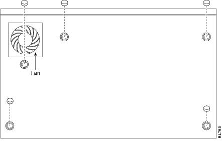
Figure 3-1 Rubber Feet Locations on Cisco 2600 Series Routers of 1-RU Height
Step 3
Caution
After the router has been installed, you must connect the chassis to a reliable earth ground. For the chassis ground connection procedures, see the "Installing the Chassis Ground Connection" section.
Mounting the Chassis in a Rack
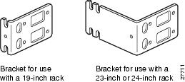
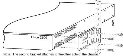
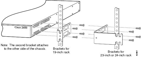
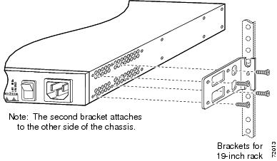
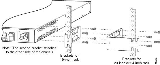
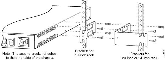
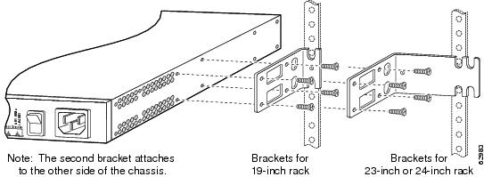
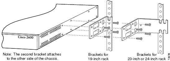
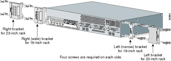
This section describes the procedures for rack-mounting the chassis. Cisco 2600 series routers with a chassis height of 1 rack-unit (1RU) ship with brackets for use with a 19-inch rack or, if specified in your order, optional larger brackets for use with a 23- or 24-inch rack. Cisco 2600 series routers with a chassis height of 2 rack-units (2RU) ship with brackets for use with 19-inch racks and with NEBS/ETSI-compliant brackets for use with 23-inch racks. The brackets are shown in Figure 3-2, Figure 3-3, and Figure 3-4.
Figure 3-2 Brackets for Cisco 261x, Cisco 262x, Cisco 26xxXM, and Cisco 265x Series Routers
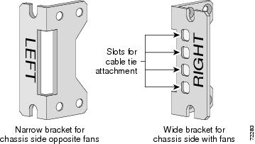
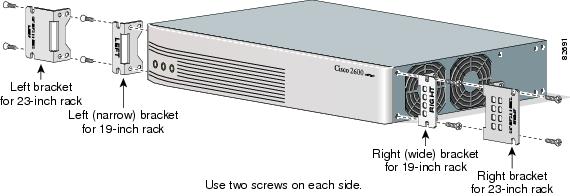
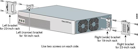
Figure 3-3 Brackets for 19-Inch Rack-Mounting of Routers with 2-RU Height
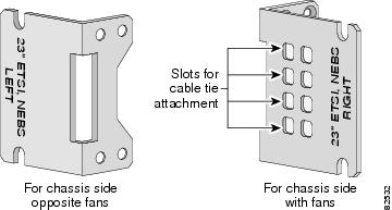
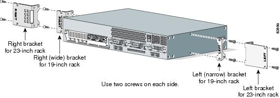
Figure 3-4 Brackets for 23-Inch Rack-Mounting of Routers with 2-RU Height
Attaching the Brackets to Cisco 261x, Cisco 262x, Cisco 26xxXM, and Cisco 265x Series Routers
To install the chassis in a rack, attach the brackets in one of the following ways:
•
•
•
Note
Note
If you are installing a Cisco 2600 series router in a 19-inch rack with a 17.75-inch opening or a 23- or 24-inch rack, orient the rack-mount brackets so that, when installed, they increase the width of the chassis. (See Figure 3-6.)
Note
Figure 3-5 Bracket Installation—Front Panel Forward (19-Inch Rack with a 17.5-Inch Opening)
Note
Figure 3-6 Bracket Installation—Front Panel Forward (19-Inch Rack with a 17.75-Inch Opening or a 23- or 24-Inch Rack)
Figure 3-7 Bracket Installation—Rear Panel Forward (19-Inch Rack with a 17.5-Inch Opening)
Figure 3-8 Bracket Installation—Rear Panel Forward (19-Inch Rack with a 17.75-Inch Opening or a 23- or 24-Inch Rack)
Figure 3-9 Center-Mount Bracket Installation—Rear Panel Forward (19-Inch Rack with a 17.75-Inch Opening or a 23- or 24-Inch Rack)
Figure 3-10 Center-Mount Bracket Installation—Rear Panel Forward (19-Inch Rack with a 17.5-Inch Opening or a 23- or 24-Inch Rack)
Figure 3-11 Center-Mount Bracket Installation—Front Panel Forward (19-Inch Rack with a 17.5-Inch Opening or a 23- or 24-Inch Rack)
Attaching the Brackets to a Router of 2-RU Height
To install the chassis in a rack, attach the brackets in one of the following ways:
•
•
•
Note
Figure 3-12 Bracket Installation—Front Mounting
Figure 3-13 Bracket Installation—Rear Mounting
Figure 3-14 Bracket Installation—Center Mounting with Front Panel Forward
Figure 3-15 Bracket Installation—Center Mounting with Rear Panel Forward
Installing the Router in a Rack
After the brackets are secured to the chassis, you can mount the chassis in a rack. Use the illustrations in the previous section as a guide to attaching the brackets to the rack.
To see translations of the warnings that appear in this publication, refer to the Cisco 2600 Series, Cisco 3600 Series, and Cisco 3700 Series Regulatory Compliance and Safety Information document that accompanied this device.
Note
Caution
After the router has been installed, you must connect the chassis to a reliable earth ground. For the chassis ground connection procedures, see the "Installing the Chassis Ground Connection" section.
Mounting the Chassis on the Wall
This section explains how to mount Cisco 2600 series routers with a chassis height of 1RU on a wall. Mounting a 2-RU chassis to a wall is not recommended, and brackets are not provided for mounting to a wall.
Tip
Use 19-inch brackets (shown in Figure 3-2) to wall-mount the chassis. The small brackets provide the most stable installation for the chassis. The rubber feet are required to provide spacing between the wall and the router for ventilation and proper cooling.
Attaching Rubber Feet to the Router
Attach the rubber feet supplied in the accessory kit. See Figure 3-1 for positioning the rubber feet.
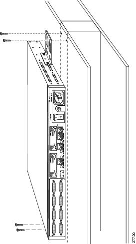
Attaching Wall-Mount Brackets to the Router
To install the router on a wall, first attach the brackets on each side of the chassis as shown in Figure 3-16, using plastic washers and slotted hex-head screws. Position the washers so that the narrow shoulder faces the router chassis.
Note
Figure 3-16 Attaching the Wall-Mount Brackets
Mounting the Router on the Wall
After fastening the brackets to the chassis, mount the chassis on the wall:
•
•
•
•
Figure 3-17 Mounting the Chassis on the Wall
After the router has been installed, you must connect the chassis to a reliable earth ground. For the chassis ground connection procedures, see the "Installing the Chassis Ground Connection" section.
Installing the Chassis Ground Connection
All Cisco 2600 series router chassis require a reliable earth ground connection. You must connect the chassis to a reliable earth ground; the ground wire must be installed in accordance with local electrical safety standards.
•
•
•
To connect the chassis to a reliable earth ground, perform the following steps:
Step 1
•
•
Step 2
Step 3
Step 4
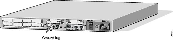
Figure 3-18 NEBS-Compliant Chassis Ground Connection Using Ground Lug, 1-RU Chassis
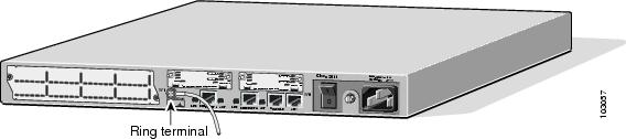
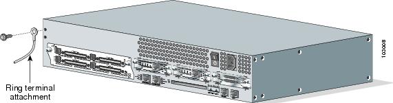
Figure 3-19 Chassis Ground Connection Using Ring Terminal, 1-RU Chassis
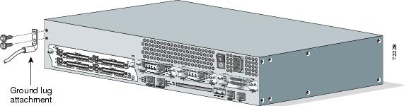
Figure 3-20 NEBS-Compliant Chassis Ground Connection Using Ground Lug, Cisco 2691
Figure 3-21 Ground Connection Using Ring Terminal, Cisco 2691
After the router has been installed and properly grounded, you can connect the power wiring; the WAN, LAN, and voice cables; and the cables for administrative access, as required for your installation. For cable connection procedures, see the "Power Connections" section, the "Connecting WAN, LAN, and Voice Cables" section, and the "Connecting to a Console Terminal or Modem" section.
Power Connections
Warning
Warning
Note
This section explains how to connect AC or DC power to Cisco 2600 series routers. It covers the following topics:
•
•
•
Connecting Routers to AC Power
If your router uses AC power, connect it to a 15 A, 120 VAC (10 A, 240 VAC) circuit with overcurrent protection.
Note
Warning
Warning
15A, 120VAC (10A, 240VAC). Statement 1005
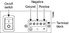
Connecting Routers to a DC-Input Power Supply
If your router has a DC-input power supply, follow the directions in this section for proper wiring.
Warning
15A, 60VDC. Statement 1005
Warning
DC Wiring Requirements
Table 3-1 summarizes the wiring requirements for Cisco 2600 series routers with a DC-input power supply.
Note
Table 3-1 DC Wiring Requirements for Cisco 2600 Series Routers
Cisco 2600 with 1-RU chassis height
-48 to -60 VDC, 4 A2
AWG 18 (1.0 mm2)
AWG 14 (2.0 mm2)
15 A maximum
Cisco 2691
24 - 36 V, 8 A,
positive or negative, single or dual sources3AWG 18
(1.0 mm2)AWG 14
(2.0 mm2)15 A maximum
36 - 60 V, 4 A,
positive or negative, single or dual sourcesAWG 18
(1.0 mm2)AWG 14
(2.0 mm2))15 A maximum
1 See the note above this table for National Electric Code wire size requirements.
2 The input voltage tolerance limits for nominal 48-V power supplies are 38 and 72 VDC.
3 The input voltage tolerance limits for nominal 24/48-V power supplies are 18 and 72 VDC.
Wiring Procedure for DC Input
To connect the router to a DC power source, perform this procedure:
Step 1
Warning
Tip
Step 2
Step 3
Warning
Caution
Caution
Note
Figure 3-22 DC Power Connections for Cisco 2600 Series Routers (Typical)
Step 4
Step 5
Connecting Routers to the Cisco Redundant Power System
If your router uses the Cisco Redundant Power System (RPS), refer to the Cisco RPS Hardware Installation Guide for instructions about the power connections. You can access this document at the location described in the"Obtaining Documentation" section on page xvii.
Connecting WAN, LAN, and Voice Cables
This chapter describes how to connect the WAN, LAN, and voice interface cables. It includes the following sections:
•
Note
Warning
Ports and Cabling
Table 3-2 summarizes some typical WAN, LAN, and voice connections for Cisco 2600 series routers.
The connections summarized here are also described in detail in the following documents:
•
•
•
Table 3-2 WAN, LAN, and Voice Connections
Ethernet
RJ-45, yellow
Ethernet hub or Ethernet switch
Straight-through Ethernet
T1/E1 WAN
RJ-48C/CA81A, blue
T1 or E1 network
RJ-48 T1
Cisco serial
60-pin D-sub
CSU/DSU and serial network or equipment
Cisco serial transition cable that matches the signaling protocol (EIA/TIA-232, EIA/TIA-449, V.35, X.21, or EIA/TIA-530) and the serial port operating mode (DTE or DCE).1
Cisco Smart serial
Cisco Smart compact connector, blue
CSU/DSU and serial network or equipment (For WIC-2T and WIC-2A/S only)
DSL
RJ-11C/CA11A, lavender
Network demarcation device for service provider's DSL interface
RJ-11
T1 digital voice
RJ-48C/CA81A, tan
Digital PBX
RJ-48 T1 cable
Analog voice FXS
RJ-11, gray
Telephone, fax
RJ-11
Analog voice FXO
RJ-11, pink
Central office, analog PBX
RJ-11
Analog voice E&M
RJ-11, brown
Analog PBX
RJ-11
BRI S/T WAN
(external NT1)RJ-48C/CA81A, orange
NT1 device or private integrated network exchange (PINX)
RJ-48
BRI U WAN
(built-in NT1)RJ-49C/CA11A, red
ISDN network
RJ-49
CT1/PRI
T1
External T1 CSU
DB-15 T1 serial cable
CT1/PRI-CSU
T1
RJ-48C/CA81A interface
RJ-48 straight-through
CE1/PRI
E1
E1 network
DB-15 to BNC, DB-15 to DB-15, DB-15 to twinax, or DB-15 to RJ-45
Token Ring
UTP, purple
STP, purple
Token Ring device
RJ-45 Token Ring cable
56/64-kbps DSU/CSU
8-pin modular, blue
RJ-48S interface
RJ-48 straight-through
1 Refer to the Cisco Modular Access Router Cable Specifications for information about selecting these cables.
LAN, WAN, and Voice Connection Procedures
Connect each WAN, LAN, and voice cable to the appropriate connector on the chassis or on a network module or interface card.
•
•
•
•
For cable pinouts, refer to the online document Cisco Modular Access Router Cable Specifications.
For more information about connecting and configuring network modules, WAN interface cards, and voice interface cards, refer to the following documents:
•
•
Connecting to a Console Terminal or Modem
Your router includes asynchronous serial console and auxiliary ports. These ports provide administrative access to your router either locally (with a console terminal) or remotely (with a modem).
Cisco provides the following cables and adapters for connecting your router to a console terminal, PC, or modem:
•
•
This section describes how to connect a console terminal or PC to the console port, and how to connect a modem to the auxiliary port. It contains the following sections:
•
•
Note
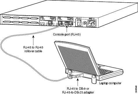
Connecting to the Console Port
To connect a console terminal or a PC running terminal emulation software to the console port on the router, perform the following procedure:
Step 1
For information about console port pinouts, refer to the Cisco Modular Access Router Cable Specifications document available online and on the Documentation CD-ROM.
Note
Step 2
Note
Figure 3-23 Connecting to a Console Terminal
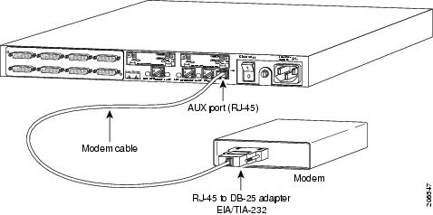
Connecting to the Auxiliary Port
To connect a modem to the auxiliary port on the router, perform the following procedure:
Step 1
For information about auxiliary port pinouts, refer to the Cisco Modular Access Router Cable Specifications document available online and on the Documentation CD-ROM.
Note
Step 2
Figure 3-24 Connecting a Modem to the Auxiliary Port
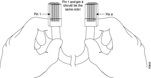
Identifying a Rollover Cable
Use a rollover cable to connect to the asynchronous serial console and auxiliary ports. You can identify a rollover cable by comparing the two modular ends of the cable. Hold the cables side-by-side, with the tab at the back. The wire connected to the pin on the outside of the left plug should be the same color as the wire connected to the pin on the outside of the right plug. (See Figure 3-25.) If your cable came from Cisco, pin 1 will be white on one connector, and pin 8 will be white on the other (a rollover cable reverses pins 1 and 8, 2 and 7, 3 and 6, and 4 and 5).
Figure 3-25 Identifying a Rollover Cable
Powering Up the Router
Warning
Caution
This section covers the following topics:
Checklist for Power Up
You are ready to power up the Cisco router if the following steps are completed:
•
•
•
•
•
Front Panel Indicators
The following indicator LEDs provide power, activity, and status information:
Routers with 1-RU Chassis Height
The following indicator LEDs provide power, activity, and status information:
•
•
–
–
–
•
–
–
Routers with 2-RU Chassis Height
The following indicator LEDs provide power, activity, and status information:
•
•
–
–
–
•
For more detailed information about the LEDs, see Appendix A, "Troubleshooting."
Power-Up Procedure
To power up your Cisco router and verify that it goes through its initialization and self-test, follow this procedure. When the procedure is finished, the Cisco router is ready to configure.
If you encounter problems when you power on the router, see Appendix A, "Troubleshooting." For information about the ROM monitor and the bootstrap program, see Appendix B, "Using the ROM Monitor." For information about the configuration register, see Appendix C, "Configuration Register."
Note
Step 1
Step 2
The following indications appear:
•
•
Depending on your installation, Fast Ethernet (0/0, 0/1) and Network Module (Active, Ready) LEDs might also come on.
If you encounter problems when you power up the router, see Appendix A, "Troubleshooting."
Messages begin to appear in your terminal emulation program window.
Caution
You may see different startup messages:
•
yourname con0 is now availablePress RETURN to get started.If SDM is installed on your router, we recommend using SDM to perform the initial configuration. For configuration procedures using SDM, refer to the quick start guide that shipped with your router.
You can also access the Cisco 2600 series routers quick start guides online at the following URL:
http://www.cisco.com/univercd/cc/td/doc/product/access/acs_mod/cis2600/26xx_qsg/index.htm
•
--- System Configuration Dialog ---At any point you may enter a question mark '?' for help.Use ctrl-c to abort configuration dialog at any prompt.Default settings are in square brackets '[]'.Would you like to enter the initial configuration dialog? [yes/no]:To learn how to use the setup command facility to configure the router, see the "Initial Configuration Using the Setup Command Facility" section. To learn how to use the CLI to configure the router, see the "Initial Configuration Using the CLI (Manual Configuration)" section.
Note
Configuring the Router
You can configure your router by using one of the following tools:
•
•
Cisco Router and Security Device Manager to perform additional configuration. See the "Initial Configuration Using the Setup Command Facility" section.•
Note
Initial Configuration Using SDM
If Cisco Router and Security Device Manager has been installed on your router, the following messages appear at the end of the startup sequence:
yourname con0 is now availablePress RETURN to get started.For configuration procedures using SDM, refer to the quick start guide that shipped with your router.
You can also access the Cisco 2600 series routers quick start guides online at the following URL:
http://www.cisco.com/univercd/cc/td/doc/product/access/acs_mod/cis2600/26xx_qsg/index.htm
Initial Configuration Using the Setup Command Facility
This section shows how to use the setup command facility to configure a hostname for the router, set passwords, and configure an interface for communication with the management network. If you see the following messages at the end of the startup sequence, the setup command facility has been invoked automatically:
--- System Configuration Dialog ---At any point you may enter a question mark '?' for help.Use ctrl-c to abort configuration dialog at any prompt.Default settings are in square brackets '[]'.Would you like to enter the initial configuration dialog? [yes/no]:The setup command facility prompts you for basic information about your router and network, and it creates an initial configuration file.The prompts vary, depending on your router model, the installed interface modules, and the software image. The following example and the user entries (in bold) are shown as examples only.
For a description of the interface numbering, see the "Interface Numbering" section on page 1-9.
Note
Step 1
Would you like to enter the initial configuration dialog? [yes/no]: yesStep 2
At any point you may enter a question mark '?' for help.Use ctrl-c to abort configuration dialog at any prompt.Default settings are in square brackets '[]'.Basic management setup configures only enough connectivityfor management of the system, extended setup will ask youto configure each interface on the systemWould you like to enter basic management setup? [yes/no]: yesStep 3
Configuring global parameters:Enter hostname [Router]: 2600Step 4
The enable secret is a password used to protect access toprivileged EXEC and configuration modes. This password, afterentered, becomes encrypted in the configuration.Enter enable secret: xxxxxxStep 5
The enable password is used when you do not specify anenable secret password, with some older software versions, andsome boot images.Enter enable password: xxxxxxStep 6
The virtual terminal password is used to protectaccess to the router over a network interface.Enter virtual terminal password: xxxxxxStep 7
Configure SNMP Network Management? [yes]:Community string [public]:Step 8
Note
Current interface summaryController Timeslots D-Channel Configurable modes StatusT1 0/0 24 23 pri/channelized Administratively upInterface IP-Address OK? Method Status ProlFastEthernet0/0 unassigned NO unset up upFastEthernet0/1 unassigned NO unset up dowStep 9
Enter interface name used to connect to themanagement network from the above interface summary: fastethernet0/0Step 10
Configuring interface FastEthernet0/0:Use the 100 Base-TX (RJ-45) connector? [yes]: yesOperate in full-duplex mode? [no]: noConfigure IP on this interface? [yes]: yesIP address for this interface: 172.1.2.3Subnet mask for this interface [255.255.0.0] : 255.255.0.0Class B network is 172.1.0.0, 16 subnet bits; mask is /16Step 11
The following configuration command script was created:hostname figenable secret 5 $1$D5P6$PYx41/lQIASK.HcSbfO5q1enable password xxxxxxline vty 0 4password xxxxxxsnmp-server community public!no ip routing!interface FastEthernet0/0no shutdownmedia-type 100BaseXhalf-duplexip address 172.1.2.3 255.255.0.0!interface FastEthernet0/1shutdownno ip address!endStep 12
[0] Go to the IOS command prompt without saving this config.[1] Return back to the setup without saving this config.[2] Save this configuration to nvram and exit.Enter your selection [2]: 2Building configuration...Use the enabled mode 'configure' command to modify this configuration.Press RETURN to get started!Step 13
2600>After you complete the initial configuration tasks, your Cisco router is ready to configure for specific functions. For configuration procedures, refer to the Software Configuration Guide for Cisco 2600 Series, Cisco 3600 Series, and Cisco 3700 Series Routers. or the Cisco IOS software configuration documentation. You can access these documents on Cisco.com and on the Documentation CD-ROM.
Initial Configuration Using the CLI (Manual Configuration)
This section shows how to bring up a command-line interface (CLI) prompt for configuration using the CLI, and it directs you to documentation for the CLI configuration.You can use the CLI if you see the following messages at the end of the startup sequence:
--- System Configuration Dialog ---At any point you may enter a question mark '?' for help.Use ctrl-c to abort configuration dialog at any prompt.Default settings are in square brackets '[]'.Would you like to enter the initial configuration dialog? [yes/no]:
Note
http://www.cisco.com/univercd/cc/td/doc/product/access/acs_mod/cis2600/26xx_qsg/index.htm
Note
Step 1
Would you like to enter the initial configuration dialog? [yes/no]: noStep 2
Would you like to terminate autoinstall? [yes] ReturnSeveral messages are displayed, ending with a line similar to the following:...Copyright (c) 1986-2000 by cisco Systems, Inc.Compiled <date> <time> by <person>Step 3
...flashfs[4]: Initialization complete.Router>Step 4
Router> enableRouter#For configuration using the CLI, refer to the Software Configuration Guide for Cisco 2600 Series, Cisco 3600 Series, and Cisco 3700 Series Routers. or the Cisco IOS software configuration documentation. You can access these documents on Cisco.com and on the Documentation CD-ROM.