Feedback
Table Of Contents
Overview of Cisco 2600 Series Routers
Modules, Interface Cards, and Memory
WAN and LAN Interface Numbering
Overview of Cisco 2600 Series Routers
Cisco 2600 series routers are modular access routers with LAN and WAN connections that can be configured by means of interchangeable modules and WAN interface cards.
This guide discusses the router models listed in Table 1-1.
This chapter includes the following sections:
Hardware Features
Table 1-1 lists the router models described in this guide and summarizes the LAN interfaces supported on each model. These router models are similar in functionality, but differ in the number of interfaces that are supported as well as the system specifications. (See Table 1-6.)
In addition to the interfaces listed in Table 1-1, Cisco 2600 series routers include the following hardware features:
•
Dynamic random-access memory (DRAM) for main memory and shared memory (Cisco 261x and Cisco 262x routers)
•
•
•
•
•
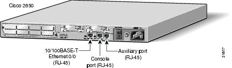
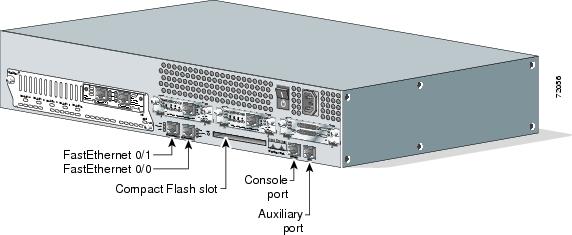
Figure 1-1 and Figure 1-2 show examples of Cisco 2600 series routers.
Note
Note
Figure 1-1 Cisco 2600 Series Router Rear Panel—Example of 1RU Router
Figure 1-2 Cisco 2600 Series Router Rear Panel—Example of 2RU Router
Reading the Front-Panel LEDs
The LEDs indicate the current operating condition of the router. By observing the LEDs, you can note any fault condition that the router is encountering, and then contact your system administrator or customer service, when necessary.
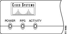
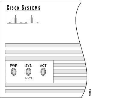
Figure 1-3 and Figure 1-4 show the locations of the LEDs on the front panel of Cisco 2600 series routers. Table 1-3 and Table 1-3 describe these LEDs.
Figure 1-3 Cisco 2600 Series Routers with 1-RU Chassis Height—Front-Panel LEDs
Table 1-2 Cisco 2600 Series Routers with 1-RU Chassis Height—Front-Panel LED Descriptions
POWER
Indicates the router's operating status. Comes on when power is supplied to the router and the router is operational.
RPS
Off—No RPS1 is attached.
On—RPS is attached and operational.
Blinking—RPS is attached, but has a failure.ACTIVITY
Off—In the Cisco IOS software, but no network activity.
Blink (500 ms ON, 500 ms OFF)—In ROMMON, no errors.
Blink (500 ms ON, 500 ms OFF, 2 seconds between codes)—In ROMMON, error detected.
Blink (less than 500 ms)—In the Cisco IOS software, the blink rate reflects the level of activity.
1 RPS = Redundant Power System
Figure 1-4 Cisco 2691—Front-Panel LEDs
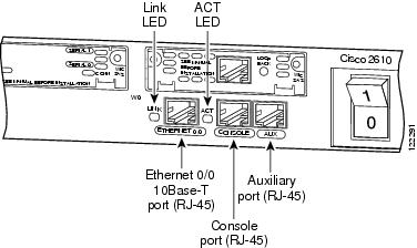
Reading the Rear-Panel LEDs
Figure 1-4 through Figure 1-10 show the location of the Cisco 2600 series rear-panel LEDs. Table 1-4 and Table 1-5 describe these LEDs.
Note
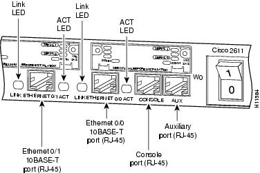
Figure 1-5 Cisco 2611—Rear-Panel LEDs
Figure 1-6 Cisco 2611—Rear-Panel LEDs
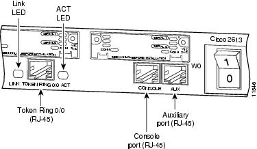
Figure 1-7 Cisco 2613—Rear-Panel LEDs
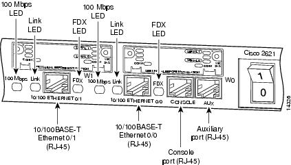
Figure 1-8 Cisco 2621—Rear-Panel LEDs
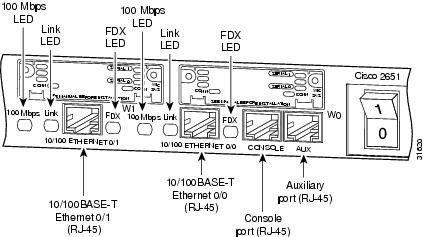
Figure 1-9 Cisco 2651—Rear-Panel LEDs
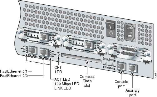
Figure 1-10 Cisco 2691—Rear-Panel LEDs
Modules, Interface Cards, and Memory
The latest information on network modules, WAN interface cards (WICs), voice interface cards (VICs), advanced integration modules (AIMs), and memory is available online and on the documentation CD-ROM.
•
•
•
–
•
–
•
–
Interface Numbering
Each interface (port) on a Cisco 2610, Cisco 2620, and Cisco 2650 series router is identified by number as described in the following sections.
WAN and LAN Interface Numbering
Cisco 2600 series routers contain the following WAN and LAN interface types:
•
•
•
The numbering format is interface-type slot-number/Interface-number. Two examples are:
•
Ethernet 0/0•
Serial 1/2The slot number is 0 for all built-in interfaces and 0 for all WIC interfaces; the slot number is 1 for network module interfaces.
Interface (port) numbers begin at 0 for each interface type, and continue from right to left and (if necessary) from bottom to top.
Figure 1-11 shows a router of 1-RU height with:
•
•
•
•
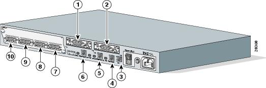
Figure 1-11 Interface Numbering in Chassis with 1-RU Height
Figure 1-12 shows a router of 2-RU height with:
•
•
•
–
–
–
Note
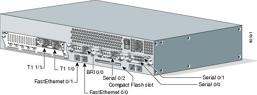
Figure 1-12 Interface Numbering in Cisco 2691 Routers
Voice Interface Numbering
Voice interfaces are numbered as follows:
chassis-slot/voice-module-slot/voice-interface
If a 4-channel voice network module is installed in chassis slot 1, the voice interfaces are:
•
•
•
•
System Specifications
Table 1-6 Cisco 261x, Cisco 262x, and Cisco 265x System Specifications
Dimensions (H x W x D)
1.69 x 17.5 x 11.8 in. (4.3 x 44.5 x 30 cm), one rack unit height
Weight
10.25 lb (4.66 kg)
Input voltage, AC power supply
Current
Frequency
Power dissipation100 to 240 VAC
1.5 A
47 to 63 Hz
75 W (maximum), 260 Btus1 /hrInput voltage, DC power supply
Current
Power dissipation-38 to -75 VDC
2.0 A
75 W (maximum), 260 Btus/hrOperating environment
32 to 104×F (0 to 40×C)
Nonoperating temperature
-40 to 158×F (-40 to 70×C)
Operating humidity
5 to 95 percent, noncondensing
Noise level
38 dBa (minimum)
Regulatory compliance
FCC Class B and Canadian DOC Class A
For more compliance information, refer to the Cisco 2600 Series, Cisco 3600 Series, and Cisco 3700 Series Regulatory Compliance and Safety Information document that accompanied your router.
Safety compliance
UL 60950; CAN/CSA C22.2 No. 60950-00; IEC 60950; AS/NZS 3260; TS001
1 Btus = British thermal units
Table 1-7 Cisco 2691 System Specifications
Dimensions (H x W x D)
3.46 x 17.07 x 11.20 in. (8.78 x 45.36 x 28.45 cm), two rack unit height
Weight
15 lb (6.80 kg)
Input voltage, AC power supply
Current emissions (AC)
Frequency
Line surge (120 VAC)
Line surge (240 VAC)
100 to 120, 120 VAC
200 to 240, 230 VAC
0.93 min. @ 120 VAC 60 Hz (when loaded at 50% or higher
47 to 63 Hz
160 VAC - 1/2 cycle
140 VAC - 5 cycles320 VAC - 1/2 cycle
280 VAC - 5 cyclesPower dissipation
105 W (maximum)
Console and auxiliary ports
RJ-45 connector
Operating humidity
5 to 95%, noncondensing
Operating temperature
32 to 104×F (0 to 40×C)
Nonoperating temperature
-40 to 158×F (-40 to 70×C)
Noise level
45 dBA (maximum)
Regulatory compliance
FCC Part 15 Class A.
For more compliance information, refer to the Cisco 2600 Series, Cisco 3600 Series, and Cisco 3700 Series Regulatory Compliance and Safety Information document that accompanied the router.
Safety compliance
UL 60950; CAN/CSA C22.2 No. 60950-00; IEC 60950; AS/NZS 3260; TS001
Regulatory Compliance
For compliance information, refer to the Cisco 2600 Series, Cisco 3600 Series, and Cisco 3700 Series Regulatory Compliance and Safety Information document that accompanied your router.