-
Cisco 1800 Series Integrated Services Routers (Fixed) Software Configuration Guide
-
Preface
-
Basic Router Configuration
-
Sample Network Deployments
-
Configuring PPP over Ethernet with NAT
-
Configuring PPP over ATM with NAT
-
Configuring a LAN with DHCP and VLANs
-
Configuring a VPN Using Easy VPN and an IPSec Tunnel
-
Configuring VPNs Using an IPSec Tunnel and Generic Routing Encapsulation
-
Configuring a Simple Firewall
-
Configuring a Wireless LAN Connection
-
Sample Configuration
-
Additional Configuration Options
-
Configuring Security Features
-
Configuring Dial Backup and Remote Management
-
Troubleshooting
-
Cisco IOS Software Basic Skills
-
Concepts
-
ROM Monitor
-
Common Port Assignments
-
Index
-
 Feedback
Table Of Contents
Configuring VPNs Using an IPSec Tunnel and Generic Routing Encapsulation
Configure Group Policy Information
Configure IPSec Transforms and Protocols
Configure the IPSec Crypto Method and Parameters
Apply the Crypto Map to the Physical Interface
Configuring VPNs Using an IPSec Tunnel and Generic Routing Encapsulation
The Cisco 1800 series integrated services fixed-configuration routers support the creation of virtual private networks (VPNs).
Cisco routers and other broadband devices provide high-performance connections to the Internet, but many applications also require the security of VPN connections which perform a high level of authentication and which encrypt the data between two particular endpoints.
Two types of VPNs are supported—site-to-site and remote access. Site-to-site VPNs are used to connect branch offices to corporate offices, for example. Remote access VPNs are used by remote clients to log in to a corporate network.
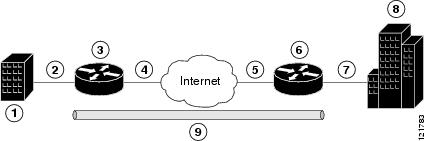
The example in this chapter illustrates the configuration of a site-to-site VPN that uses IPSec and the generic routing encapsulation (GRE) protocol to secure the connection between the branch office and the corporate network. Figure 7-1 shows a typical deployment scenario.
Figure 7-1 Site-to-Site VPN Using an IPSec Tunnel and GRE
GRE Tunnels
GRE tunnels are typically used to establish a VPN between the Cisco router and a remote device that controls access to a private network, such as a corporate network. Traffic forwarded through the GRE tunnel is encapsulated and routed out onto the physical interface of the router. When a GRE interface is used, the Cisco router and the router that controls access to the corporate network can support dynamic IP routing protocols to exchange routing updates over the tunnel, and to enable IP multicast traffic. Supported IP routing protocols include Enhanced Interior Gateway Routing Protocol (EIGRP), Routing Information Protocol (RIP), Intermediate System-to-Intermediate System (IS-IS), Open Shortest Path First (OSPF), and Border Gateway Protocol (BGP).
Note
When IP Security (IPSec) is used with GRE, the access list for encrypting traffic does not list the desired end network and applications, but instead refers to the permitted source and destination of the GRE tunnel in the outbound direction. All packets forwarded to the GRE tunnel are encrypted if no further access control lists (ACLs) are applied to the tunnel interface.
VPNs
VPN configuration information must be configured on both endpoints; for example, on your Cisco router and at the remote user, or on your Cisco router and on another router. You must specify parameters, such as internal IP addresses, internal subnet masks, DHCP server addresses, and Network Address Translation (NAT).
Configuration Tasks
Perform the following tasks to configure this network scenario:
An example showing the results of these configuration tasks is shown in the section "Configuration Example."
Note
Configure a VPN
Perform the following tasks to configure a VPN over an IPSec tunnel:
•
•
•
•
Configure the IKE Policy
Perform these steps to configure the Internet Key Exchange (IKE) policy, beginning in global configuration mode:
Configure Group Policy Information
Perform these steps to configure the group policy, beginning in global configuration mode:
Step 1
crypto isakmp client configuration group {group-name | default}
Example:
Router(config)# crypto isakmp client configuration group rtr-remoteRouter(config-isakmp-group)#Creates an IKE policy group that contains attributes to be downloaded to the remote client.
Also enters Internet Security Association Key Management Protocol (ISAKMP) policy configuration mode.
Step 2
key name
Example:
Router(config-isakmp-group)# key secret-passwordRouter(config-isakmp-group)#Specifies the IKE pre-shared key for the group policy.
Step 3
dns primary-server
Example:
Router(config-isakmp-group)# dns 10.50.10.1Router(config-isakmp-group)#Specifies the primary Domain Name Service (DNS) server for the group.
Note
Step 4
domain name
Example:
Router(config-isakmp-group)# domain company.comRouter(config-isakmp-group)#Specifies group domain membership.
Step 5
exit
Example:
Router(config-isakmp-group)# exitRouter(config)#Exits IKE group policy configuration mode, and enters global configuration mode.
Step 6
ip local pool {default | poolname} [low-ip-address [high-ip-address]]
Example:
Router(config)# ip local pool dynpool 30.30.30.20 30.30.30.30Router(config)#Specifies a local address pool for the group.
For details about this command and additional parameters that can be set, see the Cisco IOS Dial Technologies Command Reference.
Enable Policy Lookup
Perform these steps to enable policy lookup through AAA, beginning in global configuration mode:
Step 1
aaa new-model
Example:
Router(config)# aaa new-modelRouter(config)#Enables the AAA access control model.
Step 2
aaa authentication login {default | list-name} method1 [method2...]
Example:
Router(config)# aaa authentication login rtr-remote localRouter(config)#Specifies AAA authentication of selected users at login, and specifies the method used.
This example uses a local authentication database. You could also use a RADIUS server for this. See the Cisco IOS Security Configuration Guide and the Cisco IOS Security Command Reference for details.
Step 3
aaa authorization {network | exec | commands level | reverse-access | configuration} {default | list-name} [method1 [method2...]]
Example:
Router(config)# aaa authorization network rtr-remote localRouter(config)#Specifies AAA authorization of all network-related service requests, including PPP, and the method used to do so.
This example uses a local authorization database. You could also use a RADIUS server for this. See the Cisco IOS Security Configuration Guide and the Cisco IOS Security Command Reference for details.
Step 4
username name {nopassword | password password | password encryption-type encrypted-password}
Example:
Router(config)# username Cisco password 0 CiscoRouter(config)#Establishes a username-based authentication system.
This example implements a username of Cisco with an encrypted password of Cisco.
Configure IPSec Transforms and Protocols
A transform set represents a certain combination of security protocols and algorithms. During IKE negotiation, the peers agree to use a particular transform set for protecting data flow.
During IKE negotiations, the peers search in multiple transform sets for a transform that is the same at both peers. When such a transform set is found, it is selected and applied to the protected traffic as a part of both peers' configurations.
Perform these steps to specify the IPSec transform set and protocols, beginning in global configuration mode:
Step 1
crypto ipsec transform-set transform-set-name transform1 [transform2] [transform3] [transform4]
Example:
Router(config)# crypto ipsec transform-set vpn1 esp-3des esp-sha-hmacRouter(config)#Defines a transform set—An acceptable combination of IPSec security protocols and algorithms.
See the Cisco IOS Security Command Reference for detail about the valid transforms and combinations.
Step 2
crypto ipsec security-association lifetime {seconds seconds | kilobytes kilobytes}
Example:
Router(config)# crypto ipsec security-association lifetime seconds 86400Router(config)#Specifies global lifetime values used when negotiating IPSec security associations.
See the Cisco IOS Security Command Reference for details.
Note
Configure the IPSec Crypto Method and Parameters
A dynamic crypto map policy processes negotiation requests for new security associations from remote IPSec peers, even if the router does not know all the crypto map parameters (for example, IP address).
Perform these steps to configure the IPSec crypto method, beginning in global configuration mode:
Step 1
crypto dynamic-map dynamic-map-name dynamic-seq-num
Example:
Router(config)# crypto dynamic-map dynmap 1Router(config-crypto-map)#Creates a dynamic crypto map entry, and enters crypto map configuration mode.
See the Cisco IOS Security Command Reference for more detail about this command.
Step 2
set transform-set transform-set-name [transform-set-name2...transform-set-name6]
Example:
Router(config-crypto-map)# set transform-set vpn1Router(config-crypto-map)#Specifies which transform sets can be used with the crypto map entry.
Step 3
reverse-route
Example:
Router(config-crypto-map)# reverse-routeRouter(config-crypto-map)#Creates source proxy information for the crypto map entry.
See the Cisco IOS Security Command Reference for details.
Step 4
exit
Example:
Router(config-crypto-map)# exitRouter(config)#Enters global configuration mode.
Step 5
crypto map map-name seq-num [ipsec-isakmp] [dynamic dynamic-map-name] [discover] [profile profile-name]
Example:
Router(config)# crypto map static-map 1 ipsec-isakmp dynamic dynmapRouter(config)#Creates a crypto map profile.
Apply the Crypto Map to the Physical Interface
The crypto maps must be applied to each interface through which IPSec traffic flows. Applying the crypto map to the physical interface instructs the router to evaluate all the traffic against the security associations database. With the default configurations, the router provides secure connectivity by encrypting the traffic sent between remote sites. However, the public interface still allows the rest of the traffic to pass and provides connectivity to the Internet.
Perform these steps to apply a crypto map to an interface, beginning in global configuration mode:
Step 1
interface type number
Example:
Router(config)# interface fastethernet 0Router(config-if)#Enters interface configuration mode for the interface to which you want to apply the crypto map.
Step 2
crypto map map-name
Example:
Router(config-if)# crypto map static-mapRouter(config-if)#Applies the crypto map to the interface.
See th e Cisco IOS Security Command Reference for more detail about this command.
Step 3
exit
Example:
Router(config-if)# exitRouter(config)#Enters global configuration mode.
Configure a GRE Tunnel
Perform these steps to configure a GRE tunnel, beginning in global configuration mode:
Step 1
interface type number
Example:
Router(config)# interface tunnel 1Router(config-if)#Creates a tunnel interface and enters interface configuration mode.
Step 2
ip address ip-address mask
Example:
Router(config-if)# 10.62.1.193 255.255.255.252Router(config-if)#Assigns an address to the tunnel.
Step 3
tunnel source interface-type number
Example:
Router(config-if)# tunnel source fastethernet 2Router(config-if)#Specifies the source endpoint of the router for the GRE tunnel.
Step 4
tunnel destination default-gateway-ip-address
Example:
Router(config-if)# tunnel destination 192.168.101.1Router(config-if)#Specifies the destination endpoint of the router for the GRE tunnel.
Step 5
crypto map map-name
Example:
Router(config-if)# crypto map static-mapRouter(config-if)#Assigns a crypto map to the tunnel.
Note
Step 6
exit
Example:
Router(config-if)# exitRouter(config)#Exits interface configuration mode, and returns to global configuration mode.
Step 7
ip access-list {standard | extended} access-list-name
Example:
Router(config)# ip access-list extended vpnstatic1Router(config-acl)#Enters ACL configuration mode for the named ACL that is used by the crypto map.
Step 8
permit protocol source source-wildcard destination destination-wildcard
Example:
Router(config-acl)# permit gre host 192.168.100.1 host 192.168.101.1Router(config-acl)#Specifies that only GRE traffic is permitted on the outbound interface.
Step 9
exit
Example:
Router(config-acl)# exitRouter(config)#Returns to global configuration mode.
Configuration Example
The following configuration example shows a portion of the configuration file for a VPN using a GRE tunnel scenario described in the preceding sections.
!aaa new-model!aaa authentication login rtr-remote localaaa authorization network rtr-remote localaaa session-id common!username cisco password 0 cisco!interface tunnel 1ip address 10.62.1.193 255.255.255.252tunnel source fastethernet 2tunnel destination interface 192.168.101.1ip route 20.20.20.0 255.255.255.0 tunnel 1crypto isakmp policy 1encryption 3desauthentication pre-sharegroup 2!crypto isakmp client configuration group rtr-remotekey secret-passworddns 10.50.10.1 10.60.10.1domain company.compool dynpool!crypto ipsec transform-set vpn1 esp-3des esp-sha-hmac!crypto ipsec security-association lifetime seconds 86400!crypto dynamic-map dynmap 1set transform-set vpn1reverse-route!crypto map static-map 1 ipsec-isakmp dynamic dynmapcrypto map dynmap isakmp authorization list rtr-remotecrypto map dynmap client configuration address respond!crypto isakmp policy 1 ! defines the key association and authentication for ipsec tunnel.hash md5authentication pre-sharecrypto isakmp key cisco123 address 200.1.1.1!!crypto ipsec transform-set set1 esp-3des esp-md5-hmac ! defines encryption and transformset for the ipsec tunnel.!crypto map to_corporate 1 ipsec-isakmp ! associates all crypto values and peering addressfor the ipsec tunnel.set peer 200.1.1.1set transform-set set1match address 105!!!interface vlan 1 ! VLAN 1 is the internal home networkip address 10.1.1.1 255.255.255.0ip nat insideip inspect firewall in ! inspection examines outbound trafficcrypto map static-mapno cdp enable!interface fastethernet 0 ! FE0 is the outside or internet exposed interfaceip address 210.110.101.21 255.255.255.0ip access-group 103 in ! acl 103 permits ipsec traffic from the corp. router as well asdenies internet initiated traffic inbound.ip nat outsideno cdp enablecrypto map to_corporate ! applies the ipsec tunnel to the outside interface.!ip nat inside source list 102 interface Ethernet1 overload ! utilize nat overload in orderto make best use of the single address provided by the isp.ip classlessip route 0.0.0.0 0.0.0.0 210.110.101.1no ip http server!!! acl 102 associated addresses used for nat.access-list 102 permit ip 10.1.1.0 0.0.0.255 any! acl 103 defines traffic allowed from the peer for the ipsec tunnel.access-list 103 permit udp host 200.1.1.1 any eq isakmpaccess-list 103 permit udp host 200.1.1.1 eq isakmp anyaccess-list 103 permit esp host 200.1.1.1 anyaccess-list 103 permit icmp any any ! allow icmp for debugging but should be disabled dueto security implications.access-list 103 deny ip any any ! prevents internet initiated traffic inbound.! acl 105 matches addresses for the ipsec tunnel to/from the corporate network.access-list 105 permit ip 10.1.1.0 0.0.0.255 192.168.0.0 0.0.255.255no cdp run