-
Cisco 1800 Series Integrated Services Routers (Fixed) Software Configuration Guide
-
Preface
-
Basic Router Configuration
-
Sample Network Deployments
-
Configuring PPP over Ethernet with NAT
-
Configuring PPP over ATM with NAT
-
Configuring a LAN with DHCP and VLANs
-
Configuring a VPN Using Easy VPN and an IPSec Tunnel
-
Configuring VPNs Using an IPSec Tunnel and Generic Routing Encapsulation
-
Configuring a Simple Firewall
-
Configuring a Wireless LAN Connection
-
Sample Configuration
-
Additional Configuration Options
-
Configuring Security Features
-
Configuring Dial Backup and Remote Management
-
Troubleshooting
-
Cisco IOS Software Basic Skills
-
Concepts
-
ROM Monitor
-
Common Port Assignments
-
Index
-
 Feedback
Table Of Contents
Configuring a LAN with DHCP and VLANs
Verify Your DHCP Configuration
Verify Your VLAN Configuration
Maximum Switched Virtual Interfaces (SVIs)
Separate Voice and Data Subnets
Configuring a LAN with DHCP and VLANs
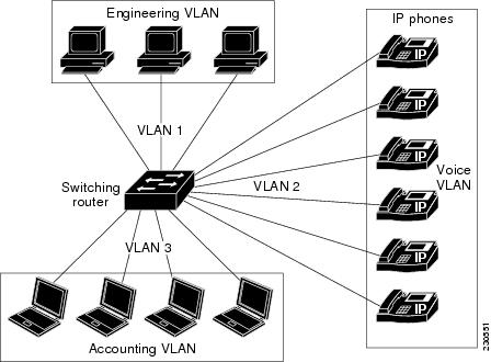
The Cisco 1800 series integrated services fixed-configuration routers support clients on both physical LANs and virtual LANs (VLANs). The routers can use the Dynamic Host Configuration Protocol (DHCP) to enable automatic assignment of IP configurations for nodes on these networks. Other interfaces and configurations of the VLANs are described in the "Switch Port Configurations" section.
Fast Ethernet LAN (with multiple networked devices)
Router and DHCP server—Cisco 1800 series integrated services router—connected to the Internet
VLAN 1
VLAN 2
DHCP
DHCP, which is described in RFC 2131, uses a client/server model for address allocation. As an administrator, you can configure your Cisco 1800 integrated services fixed-configuration router to act as a DHCP server, providing IP address assignment and other TCP/IP-oriented configuration information to your workstations. DHCP frees you from having to manually assign an IP address to each client.
When you configure a DHCP server, you must configure the server properties, policies, and DHCP options.
Note
Whenever you change server properties, you must reload the server with the configuration data from the Network Registrar database.
VLANs
The Cisco 1800 series integrated services routers (fixed) support eight Fast Ethernet ports on which you can configure VLANs. See the "Switch Port Configurations" section for a description of the interfaces and features that can be configured on the switch ports and a link to a document containing the configuration procedures.
VLANs enable networks to be segmented and formed into logical groups of users, regardless of the user's physical location or LAN connection.
Configuration Tasks
Perform the following tasks to configure this network scenario:
Note
Configure DHCP
Perform these steps to configure your router for DHCP operation, beginning in global configuration mode:
Configuration Example
The following configuration example shows a portion of the configuration file for the DCHP configuration described in this chapter.
ip dhcp excluded-address 192.168.9.0!ip dhcp pool dpool1import allnetwork 10.10.0.0 255.255.255.0default-router 10.10.10.10dns-server 192.168.35.2domain-name cisco.com!ip domain name smallbiz.comip name-server 192.168.11.12Verify Your DHCP Configuration
Use the following commands to view your DHCP configuration.
•
•
•
Router# show ip dhcp importAddress Pool Name: dpool1Router# show ip dhcp poolPool dpool1 :Utilization mark (high/low) : 100 / 0Subnet size (first/next) : 0 / 0Total addresses : 254Leased addresses : 0Pending event : none1 subnet is currently in the pool :Current index IP address range Leased addresses10.10.0.1 10.10.0.1 - 10.10.0.254 0Router# show ip dhcp server statisticsMemory usage 15419Address pools 1Database agents 0Automatic bindings 0Manual bindings 0Expired bindings 0Malformed messages 0Secure arp entries 0Message ReceivedBOOTREQUEST 0DHCPDISCOVER 0DHCPREQUEST 0DHCPDECLINE 0DHCPRELEASE 0DHCPINFORM 0Message SentBOOTREPLY 0DHCPOFFER 0DHCPACK 0DHCPNAK 0Router#Configure VLANs
Perform these steps to configure VLANs on your router, beginning in global configuration mode:
Step 1
vlan ?
Example:
Router# config tRouter(config)#vlan ?WORD ISL VLAN IDs 1-4094accounting VLAN accounting configurationifdescr VLAN subinterface ifDescrRouter(config)#vlanEnters VLAN configuration mode.
Step 2
ISL VLAN ID
Example:
Router(config)#vlan 2Router(config-vlan)#Adds VLANs, with identifiers ranging from
1- 4094.For details about this command and additional parameters that can be set, see the Cisco IOS Switching Services Command Reference.
Step 3
exit
Example:
Router(config-vlan)#exitRouter(config)#Updates the VLAN database, propagates it throughout the administrative domain, and returns to global configuration mode.
Verify Your VLAN Configuration
Use the following commands to view your VLAN configuration.
•
•
Router# vlan databaseRouter(vlan)# showVLAN ISL Id: 1Name: defaultMedia Type: EthernetVLAN 802.10 Id: 100001State: OperationalMTU: 1500Translational Bridged VLAN: 1002Translational Bridged VLAN: 1003VLAN ISL Id: 1002Name: fddi-defaultMedia Type: FDDIVLAN 802.10 Id: 101002State: OperationalMTU: 1500Bridge Type: SRBTranslational Bridged VLAN: 1Translational Bridged VLAN: 1003VLAN ISL Id: 1003Name: token-ring-defaultMedia Type: Token RingVLAN 802.10 Id: 101003State: OperationalMTU: 1500Bridge Type: SRBRing Number: 0Bridge Number: 1Parent VLAN: 1005Maximum ARE Hop Count: 7Maximum STE Hop Count: 7Backup CRF Mode: DisabledTranslational Bridged VLAN: 1Translational Bridged VLAN: 1002VLAN ISL Id: 1004Name: fddinet-defaultMedia Type: FDDI NetVLAN 802.10 Id: 101004State: OperationalMTU: 1500Bridge Type: SRBBridge Number: 1STP Type: IBMVLAN ISL Id: 1005Name: trnet-defaultMedia Type: Token Ring NetVLAN 802.10 Id: 101005State: OperationalMTU: 1500Bridge Type: SRBBridge Number: 1STP Type: IBMRouter# show vlan-switchVLAN Name Status Ports---- -------------------------------- --------- -------------------------------1 default active Fa0, Fa1, Fa2, Fa31002 fddi-default active1003 token-ring-default active1004 fddinet-default active1005 trnet-default activeVLAN Type SAID MTU Parent RingNo BridgeNo Stp BrdgMode Trans1 Trans2---- ----- ---------- ----- ------ ------ -------- ---- -------- ------ ------1 enet 100001 1500 - - - - - 1002 10031002 fddi 101002 1500 - - - - - 1 10031003 tr 101003 1500 1005 0 - - srb 1 10021004 fdnet 101004 1500 - - 1 ibm - 0 01005 trnet 101005 1500 - - 1 ibm - 0 0Router#Switch Port Configurations
The 8 high speed Ethernet ports on the Cisco 1800 (fixed) integrated router supports 8 VLANs per port. To configure and verify VLANs on the switch ports see the the "Configure VLANs" section and the "Verify Your VLAN Configuration" section.
Figure 5-1 VLAN Configuration on the Cisco 1800 (Fixed) Router Showing Three VLAN Segments
Other procedures for configuring the switch ports, including configuration examples and information on the features and interfaces are in the Cisco HWIC-4ESW and HWIC-9ESW EtherSwitch Interface Cards document on Cisco.com. See this document to configure the switch ports. The configuration procedures described in this document are listed below.
•
•
•
•
•
•
•
•
•
•
•
•
•
This section briefly describes the features and interfaces that can be configured on the VLANs assigned to the switch ports and any differences between the configurations for the HWIC-4ESW and HWIC-9ESW and the configuration of the switch ports.
VLAN Trunking Protocol (VTP)
VLAN Trunking Protocol(VTP) supports three types of VTP modes - server, client and transparent modes. In VTP server mode, you create, modify and delete VLANs and specify other configuration parameters such as the VTP version for the entire VTP domain. VTP clients behave the same way as VTP servers, but you cannot create, change or delete VLANs on a VTP client. A VTP transparent switch does not advertise its' VLAN configuration, and does not synchronize its VLAN configuration based on received advertisements.
802.1x Authentication
The switch port determines whether a client is granted access to the network. In the default setting, the port is in the unauthorized state. While in this state, the port disallows all ingress and egress traffic except for 802.1x packets. When a client has successfully authenticated, the port changes to the authorized state, allowing all traffic for the client to flow normally.
If a client that does not support 802.1x is connected to an unauthorized 802.1x port, the switch requests the client's identity. In this situation, the client does not respond to the request, the port remains in the unauthorized state, and the client is not granted access to the network.
The 802.1x protocol supports authentication and full authentication, authorization, and accounting [AAA] and RADIUS modes with port VLAN ID (PVID) and voice VLAN ID (VVID); and with VLAN assignment with guest VLAN single and multi-host support on the Cisco 1800 (fixed) Configuration Series.
Note
Layer 2 Interfaces
The integrated switch ports support Layer 2 switching across Ethernet ports based on Cisco IOS Catalyst Software. They support simultaneous, parallel connections between Layer 2 Ethernet segments. Switched connections between Ethernet segments last only for the duration of the packet. Different connections can be made for different segments for the next packet. You can configure a range of Layer 2 interfaces, define a range macro, set the interface speed, set the duplex mode, and add a description for the interface.
MAC Table Manipulation
The MAC table is configured to provide port security. The switch ports use the MAC address tables to forward traffic between the ports. All MAC addresses in the address table are associated with one or more ports. The MAC tables include the following types of addresses:
•
•
•
The Cisco 1800 (Fixed) Configuration Series supports 100 secure and static MAC addresses. General MAC addresses are supported for 50 users.
Maximum Switched Virtual Interfaces (SVIs)
A switch virtual interface (SVI) represents a VLAN of switch ports as one interface to the routing or bridging function in the router. Only one SVI can be associated with a VLAN; it is necessary to configure an SVI for a VLAN only when you wish to route between VLANs, when you wish to configure fallback-bridge nonroutable protocols between VLANs, or when you wish to provide IP host connectivity. Eight SVI interfaces are supported on each port of the fixed router
Switched Port Analyzer (SPAN)
You can configure SPAN sessions using parameters that specify the type of network traffic to monitor. SPAN sessions allow you to monitor traffic in one or more interfaces and allow you to send ingress traffic, egress traffic or both to one destination interface.
You can enable spanning tree on a per-VLAN basis and configure various spanning tree features. All frames have 802.1q tags.
IP Multicast Switching
Multicast switching is Layer 3 switching. To configure Multicast switching, the maximum number of configured VLANs must be less than or equal to 242. The maximum number of multicast groups is equal to to the maximum number of VLANs.
You can configure your router to enable multi-cast switching globally, enable IP Protocol Independent Multicast (PIM) on a Layer 3 interface, and verify the Multicast Layer 3 switching information.
Note
Per-Port Storm Control
You can use these per-port storm control techniques to block the forwarding of unnecessary, flooded traffic.
Fallback Bridging
With Fallback Bridging, the switch bridges together two or more VLANs or routed ports, essentially connecting multiple VLANs within one bridge domain.
To configure Fallback Bridging for a set of SVIs, the SVIs must be assigned to bridge groups. All bridges in the same group belong to the same bridge domain. Each SVI can be assigned to only one bridge group.
Separate Voice and Data Subnets
For ease of network administration and increased scalability, network managers can configure the switch ports to support Cisco IP phones such that the voice and data traffic reside on separate subnets.
IGMP Snooping
By default, IGMP Snooping is globally enabled on the switch ports. When globally enabled or disabled, it is also enabled or disabled on all VLAN interfaces. It can be enabled and disabled on a per-VLAN basis.
Note