-
Cisco Prime Performance Manager User Guide, 1.4
-
Preface
-
Prime Performance Manager Overview
-
Managing Gateways and Units Using the Command Line Interface
-
Managing the Web Interface
-
Integrating Prime Performance Manager with Prime Central
-
Discovering Network Devices
-
Managing Users
-
Managing Reports and Dashboards
-
Managing Devices
-
Managing Network Alarms and Events
-
Managing Thresholds
-
Displaying System Properties, Statuses, Messages, and Logs
-
Managing Gateways and Units
-
Configuring Prime Performance Manager for Firewalls
-
Backing Up and Restoring Prime Performance Manager
-
Prime Performance Manager and IPv6
-
Commands Reference
-
Predefined Thresholds
-
Glossary
-
Index
-
 Feedback
Table Of Contents
Configuring Prime Performance Manager for Firewalls
Configuring Gateways and Units for Firewalls
Configuring Web Client and Gateway Communication
Configuring Gateway and Unit Communication
Configuring Unit and Device Communication
Configuring Prime Performance Manager for Firewalls
The following topics tell you how to configure Prime Performance Manager for firewalls:
•
Configuring Gateways and Units for Firewalls
Gateway-to-Unit Connectivity
Prime Performance Manager runs on standard IP-connected networks and has the flexibility to adapt to different network environments including firewalls and Secure Sockets Layer (SSL) connectivity. Prime Performance Manager can run in each of these environments individually, or in any combination of networking environments.
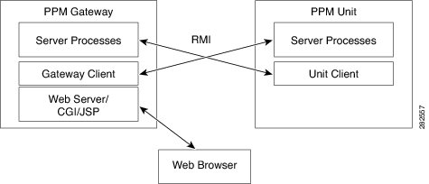
Figure 13-1 shows the communication elements between the Prime Performance Manager gateway and units. Communication elements include:
•
•
Figure 13-1 Prime Performance Manager Communication
RMI is a Java-based technology that allows one Java application to communicate with another Java application (usually residing on different hosts) using remote method invocation. RMI manages method parameters and return values using Java object serialization. RMI uses TCP as the default communication mechanism.
The following RMI components run on Prime Performance Manager gateways and units:
•
•
•
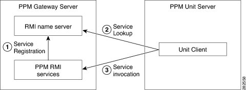
Figure 13-2 RMI Components
When the Prime Performance Manager gateway starts, the RMI services register with the RMI name server. These registered RMI services have one single published IP address.
When the Prime Performance Manager unit starts, it establishes a TCP connection to the RMI name server and performs a service lookup. The RMI name server returns the published IP address for the Prime Performance Manager RMI services. The unit then establishes another TCP connection to the published IP address of Prime Performance Manager RMI services for unit client and server communication.
Configuring Gateways and Units for Firewalls
Configuring Prime Performance Manager for firewalls includes communication through firewalls between:
•
•
•
Configurations for each are provided in the following topics:
•
•
•
Configuring Web Client and Gateway Communication
If a gateway and unit are installed on the same server and you only want to enable communication from web clients to the gateway, open the firewall WEB_PORT port. No additional changes are needed. By default, WEB_PORT is 4440. To change it to a different port, you can use the ppm jspport command. See ppm jspport, for more information.
Configuring Gateway and Unit Communication
To enable the Prime Performance Manager gateway to communicate with units through a firewall, provision the firewall to allow Prime Performance Manager packets to pass through it. Ports used by Prime Performance Manager are configured in the System.properties file. System.properties is located in /opt/CSCOppm-gw/properties or /opt/CSCOppm-unit/properties. If you installed Prime Performance Manager in a different directory, the file resides in that directory.
Table 13-1 lists the Prime Performance Manager ports and firewall requirements.
Table 13-1 Prime Performance Manager Ports
RMIREGISTRY_PORT
The port on which the RMI naming server listens. You must specify a port number; 0 is not allowed.
DATASERVER_PORT
The port on which the data service listens. If you specify 0, Prime Performance Manager uses a random available port, 1024 and above. Prime Performance Manager maintains the chosen port until the next server restart. 45751 and 55751 are good alternate ports for gateways and units respectively.
LOGINSERVER_PORT
The port on which the log in service listens. If you specify 0, Prime Performance Manager uses a random available port, 1024 and above. Prime Performance Manager maintains the chosen port until the next server restart. 45752 and 55752 are good alternate ports for gateways and units respectively.
WEB_PORT
The port on which the Prime Performance Manager gateway listens. You must specify a port number; 0 is not allowed. To change it to a different port, you can use the ppm webport command. See ppm jspport, for more information.
CLIENT_PORT
The port on which the Prime Performance Manager server listens for RMI callbacks (unsolicited notifications):
•
•
•
Because a gateway server can connect to multiple units, specify a range if more than one unit is defined in the deployment. Because a unit connects to only one gateway, you only need to specify a single port.
To provision the firewall for gateway and unit communications:
Step 1
Step 2
Step 3
If you installed Prime Performance Manager in the default directory, System.properties is located in the /opt/CSCOppm-gw/properties or /opt/CSCOppm-unit/properties directory.
If you installed Prime Performance Manager in a different location, specify the path where you installed Prime Performance Manager in place of the default (/opt) path.
Step 4
Caution
Step 5
Gateway:
RMIREGISTRY_PORT = 45742DATASERVER_PORT = 45751LOGINSERVER_PORT = 45752CLIENT_PORT = 33459-33479WEB_PORT = 4440JSP_PORT = 4440Unit:
RMIREGISTRY_PORT = 55742DATASERVER_PORT = 45751LOGINSERVER_PORT = 45752CLIENT_PORT = 33459Step 6
On Cisco devices, you can use extended access lists to allow the chosen TCP port numbers to pass between the appropriate interface(s). Assuming a single device separates the Prime Performance Manager gateway and unit servers, you can use the following extended access list:
Unit interface:
Interface FastEthernet 1/1ip address 192.168.1.100 255.255.255.0ip access-group unit-to-gateway inGateway interface:
interface FastEthernet 2/1ip address 192.168.2.100 255.255.255.0ip access-group gateway-to-unit inThese entries allow data to flow between the gateway and unit that initiated the session. Without these entries, units cannot access the gateway server.
Here is an access list entry to allow the unit and web browser connections to the gateway:
ip access-list extended unit-to-gateway10 permit tcp any established20 permit tcp 192.168.1.0 0.0.0.255 host 192.168.2.2 eq 4574230 permit tcp 192.168.1.0 0.0.0.255 host 192.168.2.2 eq 4575140 permit tcp 192.168.1.0 0.0.0.255 host 192.168.2.2 eq 4575250 permit tcp 192.168.1.0 0.0.0.255 host 192.168.2.2 eq 3345960 permit tcp 192.168.1.0 0.0.0.255 host 192.168.2.2 eq 4440Here is an access list to allow gateway connections to the unit:
ip access list extended gateway-to-unit20 permit tcp 192.168.1.0 0.0.0.255 host 192.168.2.2 eq 5574230 permit tcp 192.168.1.0 0.0.0.255 host 192.168.2.2 eq 5575140 permit tcp 192.168.1.0 0.0.0.255 host 192.168.2.2 eq 5575250 permit tcp 192.168.1.0 0.0.0.255 host 192.168.2.2 eq 33459Step 7
#cd /opt/CSCOppm-gw/bin/ppm restartThe gateway and collocated unit processes restart using the new ports.
Step 8
#cd /opt/CSCOppm-unit/bin/ppm restartBoth access list examples allow established TCP connections. When a unit or gateway establishes a TCP connection to the other end, it uses a fixed destination port. However, the source port from the initiating party is random. The established keyword allows a returning TCP packet to go back to the random initiating source port.
Configuring Unit and Device Communication
For units to communicate to devices through a firewall, SNMP Port 161 must be open. If you use reports that require SSH or Telnet, such as Y.1731 or EVC reports, the SSH or Telnet ports must be open between the units and devices as specified in the Telnet/SSH tab under Administration. The default port for Telnet is 23 and the default port for SSH is 22. The SNMP Trap port 162 does not need to be opened between devices and the units since PPM does not process SNMP traps from devices.