Table Of Contents
Icon and Button Reference
Icons
Network Element Icons
Business Element Icons
Logical Inventory Icons
Physical Inventory Icons
Links
Link Icons
Link Colors
Link Characteristics
Severity Icons
Buttons
Prime Network Vision Buttons
Table Buttons
Link Filtering Buttons
Prime Network Events Buttons
Ticket Properties Buttons
Report Manager Buttons
Badges
VNE Communication State Badges
VNE Investigation State Badges
Network Element Technology-Related Badges
Alarm and Ticket Badges
Icon and Button Reference
The following topics identify the buttons, icons, and badges used in Cisco Prime Network Vision (Prime Network Vision) and Cisco Prime Network Events (Prime Network Events):
• Icons
Icons
•Links
•Severity Icons
•Buttons
•Badges
Icons
The following topics describe the icons used in Prime Network Vision:
•Network Element Icons
•Business Element Icons
•Logical Inventory Icons
•Physical Inventory Icons
Network Element Icons
Table A-1 Prime Network Vision Network Element Icons
Icon
|
Network Element
|
|
Access pseudowire
Router
|
|
ATM switch
|
|
Basic rate access (BRA)
|
|
Cisco 7600 series router
|
|
Cisco ASR 1000 series router
|
|
Cisco ASR 5000 series router
|
|
Cisco ASR 9000 series router
|
|
Cisco CRS series router
|
|
Cisco IOS XR 12000 series router
|
|
Cisco MWR 3941
|
|
Cisco Nexus 1000 series
|
|
Cisco Unified Computing System (UCS) 6100 series
|
|
Cloud
|
|
Digital subscriber line access multiplexer (DSLAM)
|
|
Ethernet switch
|
|
Generic SNMP device
|
|
Ghost, or unknown device
|
|
ICMP device
|
|
Lock, or security violation; viewable by a user with a higher permission level
|
|
Missing icon, displayed in either of the following situations:
•A device has been deleted via Prime Network Administration, but remains in the map.
•A unique icon for an element (physical or logical) does not exist.
|
|
Sun Netra server
|
|
PC
|
|
Printer
|
|
Service control switch
|
|
WiFi element
|
Related Topics
•Badges
•Prime Network Vision Buttons
•Logical Inventory Icons
Business Element Icons
Table A-2 Prime Network Vision Business Element Icons
Icon
|
Business Element
|
|
Aggregation or root node
|
|
Backup pseudowire edge
|
|
Business IP interface
|
|
Connection termination point (TP)
Ethernet flow point (EFP)
MToP service
|
|
Customer
|
|
EFP cross-connect
|
|
Ethernet service
|
|
Ethernet virtual connection (EVC)
|
|
Label-Switched Path (LSP) end point
|
|
LSP mid point
|
|
Network LSP
|
|
Network pseudowire
|
|
Network TP tunnel
|
|
Network VLAN
|
|
Protected LSP
|
|
Pseudowire edge
|
|
Pseudowire switching entity
|
|
Site
|
|
Subnet
|
|
Switching entity
|
|
TP tunnel end point
|
|
Virtual router
|
|
VPLS forward
|
|
VPLS instance
|
|
VPN
|
|
Working LSP
|
Logical Inventory Icons
Table A-3 describes the icons used in logical inventory.
Table A-3 Logical Inventory Icons
Icon
|
Logical Inventory Item
|
|
Access Lists
ATM Traffic Profiles
Bidirectional Forwarding Detection (BFD)
Cisco Discovery Protocol (CDP)
Clock
Ethernet LMI
Frame Relay Traffic Profiles
IP SLA
|
Link Layer Discovery Protocol (LLDP)
Modular OS
Operating System
Operations, Administration, and Maintenance (OAM)
Resilient Ethernet Protocol (REP)
Session Border Controller
Spanning Tree Protocol
Tunnel Traffic Descriptors
|
|
Access Gateway
ARP Entity
Bridges
Ethernet Link Aggregation
GRE Tunnels
ICCP Redundancy container
IMA Groups
Local Switching
LSEs
MLPPP
|
MPBGPs
Multiple Spanning Tree protocol (MST) instance
OSPF Processes
Pseudowires
Routing Entities
Traffic Engineering Tunnels
VC Switching Entities
VRFs
VSIs
|
|
Bridge
|
|
Connectivity Fault Management (CFM) Maintenance Association
|
|
CFM Maintenance Domain
|
|
Connectivity Fault Management
|
|
Context, for devices that support multiple virtual contexts
|
|
Cross-VRF
|
|
Encapsulation
|
|
ICCP Redundancy group
|
|
Inverse Multiplexing over ATM (IMA) group
|
|
Label switching
|
|
Layer 2 Tunnel Protocol (TP) peer
|
|
Logical inventory
|
|
Virtual Switch Interface (VSI)
|
|
VLAN Trunk Protocol (VTP)
|
Related Topics
•Network Element Icons
•Prime Network Vision Buttons
•Physical Inventory Icons
Physical Inventory Icons
Table A-4 describes the icons used in physical inventory.
Table A-4 Physical Inventory Icons
Icon
|
Device
|
|
Chassis
|
|
Shelf
|
|
Slot/Subslot
|
|
Port/Logical Port
|
|
Unmanaged Port
|
Related Topics
•Network Element Icons
•Prime Network Vision Buttons
•Logical Inventory Icons
Links
The following sections describe link icons and characteristics:
•Link Icons
•Link Colors
•Link Characteristics
Link Icons
Table A-5 identifies the available link types and their representation in Prime Network Vision.
Table A-5 Prime Network Vision Link Icons
Icon
|
Description
|
Icon
|
Description
|
|
Asynchronous Transfer Mode
|
|
Unknown
|
|
Bidirectional Forwarding Detection
|
|
Physical layer
|
|
Border Gateway Protocol
|
|
Private Network-to-Network Interface
|
|
Business link
|
|
Point-to-Point Protocol
|
|
Ethernet
|
|
Pseudowire
|
|
Frame Relay
|
|
Serial
|
|
Generic Routing Encapsulation
|
|
MPLS TE Tunnel
|
|
Internal
|
|
MPLS TP Tunnel
|
|
IP
|
|
VLAN
|
|
Link aggregation group
|
|
IPv6 VPN over IPv4-MPLS
|
|
Multilink Point-to-Point Protocol
|
|
VPN
|
|
MPLS
|
Link Colors
Table A-6 Link Colors and Severity
Color
|
Severity
|
Description
|
|
Critical
|
Critical alarm is on the link.
|
|
Major
|
Major alarm is on the link.
|
|
Minor
|
Minor alarm is on the link.
|
|
Normal
|
Link is operating normally.
|
|
Selected
|
Link is selected.
|
Link Characteristics
Table A-7 Link Characteristics
Example
|
Description
|
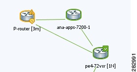
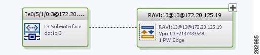
Solid Line vs. Dashed Line
|
|
Solid line—Physical, topological, or service link, such as a link between two devices.
|
|
Dashed line—Association or business link between such elements as EVCs, VPLS service instances, or VPN components.
|
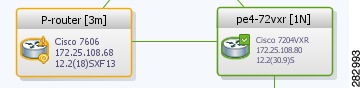
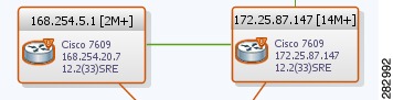
Link Widths
|
|
Normal—Contains links of the same group. Available groups are:
•Business
•GRE
•MPLS-TP
•Pseudowire
•VLAN
•All others
|
|
Wide—Aggregated links that contain links of different groups.
When viewing a map at a low zoom level, aggregated links cannot be distinguished in the GUI.
|
|
Tunnel—The center color represents the severity of any alarms on the link.
|
Arrowhead vs. No Arrowhead
|
|
No arrowhead—Bidirectional link.
|
|
Arrowhead Unidirectional link, with the flow in the direction of the arrowhead.
|
Related Topics
•Severity Icons
•Network Element Icons
•Prime Network Vision Buttons
Severity Icons
Table A-8 identifies the severity icons used in Prime Network Events and Prime Network Vision.
The icons and colors are used as follows:
•The icons are used to indicate the severity of alarms in Prime Network Events and tickets in the Prime Network Vision ticket pane.
•The icons are used as badges in Prime Network Vision maps to indicate the highest severity alarm that is not acknowledged for the associated network element.
•The colors are used with network elements in Prime Network Vision to indicate the severity of the highest uncleared ticket on the element.
•The colors are used with links in Prime Network Vision to indicate the severity of the alarm on the link. For more information, see Link Colors.
Table A-8 Severity Indicators
Icon
|
Color
|
Severity
|
|
Red
|
Critical
|
|
Orange
|
Major
|
|
Yellow
|
Minor
|
|
Light Blue
|
Warning
|
|
Green
|
Cleared, Normal, or OK
|
|
Medium Blue
|
Information
|
|
Dark Blue
|
Indeterminate
|
Related Topics
•Prime Network Vision Buttons
•Ticket Properties Buttons
•Badges
Buttons
The following topics describe the buttons used in Prime Network Vision:
•Prime Network Vision Buttons
•Table Buttons
•Link Filtering Buttons
•Prime Network Events Buttons
•Ticket Properties Buttons
•Report Manager Buttons
Prime Network Vision Buttons
Table A-9 Prime Network Vision Buttons
Button
|
Function
|
Map Options
|
|
Creates a new map in the database.
|
|
Opens a map saved in the database using the Open dialog box.
|
|
Adds a network element to the map or to the subnetwork selected in the navigation pane and displayed in the content pane.
|
|
Saves the current map (the background and the location of devices) to the database.
|
Viewing Options
|
|
Displays the map view in the Prime Network Vision content pane (the button toggles when selected or deselected).
|
|
Displays the list view in the Prime Network Vision content pane (the button toggles when selected or deselected).
|
|
Displays the links view in the Prime Network Vision content pane (the button toggles when selected or deselected).
|
Overlay Tools
|
|
Chooses and displays an overlay of a specific type on top of the elements displayed in the content pane in the map view.
When an overlay is selected, all the elements and links that are part of the overlay are colored, and those that are not part of the overlay are dimmed.
|
|
Displays or hides a previously defined overlay of a specific type on top of the elements displayed in the content pane in map view.
|
|
Refreshes the overlay.
|
Navigation Tools
|
|
Moves up a level in the navigation pane and map pane to enable you to view different information.
|
|
Opens the Link Filter dialog box, enabling you to display or hide different types of links in the map and links views.
If a link filter is applied to the map, the Link Filter Applied button is displayed instead.
|
|
Indicates a link filter is currently applied to the map and opens the Link Filter dialog box so you can remove or modify the existing link filter.
If no link filter is applied to the map, the Link Filter button is displayed instead.
|
|
Opens a window displaying an overview of the network.
|
Search Tools
|
|
Finds the previous instance of the search string entered in the Find in Map dialog box.
|
|
Opens the Find in Map dialog box, enabling you to find a device or aggregation in the map by its name or IP address.
|
|
Finds the next instance of the search string entered in the Find in Map dialog box.
|
|
Opens the Find Business Tag dialog box, enabling you to find and detach a business tag according to a name, key, or type.
|
Map Zoom and Layout Tools
|
|
Defines the way in which the NES are arranged in the Prime Network Vision map view: circular, hierarchical, orthogonal, or symmetric.
|
|
Fits the entire subnetwork or map in the map pane.
|
|
Activates the normal selection mode.
|
|
Activates the zoom selection mode, which enables you to select an area in the map pane to zoom in on by clicking and dragging.
|
|
Activates the pan mode, which enables you to move around in the map pane by clicking and dragging.
|
|
Displayed if Prime Network Activation is installed with Prime Network Vision.
Opens the Activation dialog box.
|
|
Displayed if Prime Network Activation is installed with Prime Network Vision.
Opens the Activation List dialog box.
|
Print Preview Options
|
|
Opens the Printer Setup dialog box so you can specify your print settings.
|
|
Opens the Print dialog box so you can print the displayed network or map to the required printer.
|
|
Zooms in on the network or map.
|
|
Zooms out of the network or map.
|
|
Displays the entire network or map in the Print Preview window.
|
Related Topics
•Network Element Icons
•Table Buttons
•Logical Inventory Icons
Table Buttons
Table A-10 Table Buttons
Icon
|
Name
|
Description
|
|
Find
|
Searches the current table for the string you enter.
|
|
Export to CSV
|
Exports the information displayed in the list view. Either the selected rows are exported, or, when nothing is selected, the entire table is exported.
|
|
Sort Table Values
|
Sorts the information displayed in the list view (for example, according to element category).
|
|
Filter
|
Filters the information displayed in the table by the criteria you specify.
|
|
Clear Filter
|
Clears the existing filter.
|
|
Show All Rows
|
Displays all table rows that meet the current filtering criteria.
|
|
Show Only Selected Rows
|
Displays only the rows that you select.
|
Related Topics
•Link Filtering Buttons
•Prime Network Vision Buttons
•Physical Inventory Icons
Link Filtering Buttons
Table A-11 Link Filtering Buttons
Button
|
Name
|
Description
|
|
All Links
|
Displays the complete list of links for the selected context (map or aggregation). In other words, the list is not filtered and all the links are displayed, including external links.
|
|
External Links
|
Displays links with only one side of the link in this context (map or aggregation) and the other side either not in the map or outside the selected context.
|
|
Flat Links
|
Displays the links currently visible on the map for the selected context (map or aggregation), excluding any thumbnails.
|
|
Deep Links
|
Displays the links for the current aggregation where both endpoints are within the currently selected context.
|
Related Topics
•Prime Network Vision Buttons
•Prime Network Events Buttons
•Physical Inventory Icons
Prime Network Events Buttons
Table A-12 Prime Network Events Buttons
Button
|
Function
|
|
Displays the previous page of events in the Prime Network Events window.
|
|
Displays the next page of events in the Prime Network Events window.
|
|
Refreshes the events displayed in the log by querying the database. If a filter is active, the refresh is done according to the filter. The log returns to the beginning of the list, displaying the events in ascending or descending order depending on the order of the current list. Descending order means that the last event is displayed first.
|
|
Displays the Prime Network Events Filter dialog box, which enables you to define a filter for the events displayed in the Prime Network Events log.
|
|
Toggles automatic refresh of event data on and off. You define the refresh-time period (in seconds) in the Prime Network Events Options dialog box. The default is 60 seconds. If a filter is active, the refresh is done according to the filter.
|
|
Displays the properties of the selected event or ticket in the Properties pane.
|
Related Topics
•Severity Icons
•Ticket Properties Buttons
•Alarm and Ticket Badges
Ticket Properties Buttons
Table A-13 Ticket Properties Window Buttons
Icon
|
Description
|
|
Refreshes the information displayed in the Ticket Properties dialog box.
|
|
Acknowledges that the ticket is being handled. The status of the ticket is displayed as true in the ticket pane and in the Ticket Properties dialog box.
If a ticket was acknowledged, and some events were correlated to it afterward, then the ticket is considered to have not been acknowledged.
This button is enabled only if the ticket is not acknowledged.
|
|
Requests the relevant Prime Network system to remove the faulty network element from the Prime Network Vision networking inventory. In addition, it sets the ticket to Cleared severity or status (the icon is displayed in green) and automatically changes the acknowledged status of the ticket to true.
This button is enabled only if the severity of the alarm is higher than Cleared or Normal.
|
|
Saves the notes for the selected ticket.
This button is enabled only when text is entered in the Notes field of the Notes tab.
|
Related Topics
•Severity Icons
•Prime Network Events Buttons
•Table Buttons
Report Manager Buttons
Table A-14 Report Manager Buttons
Icon
|
Name
|
Description
|
|
Define Report of This Type
|
Enables you to define a report of this type that is suited specifically to your environment.
|
|
Delete
|
Deletes one or more folders that you created.
|
|
Delete Report
|
Deletes the selected report.
|
|
Move
|
Moves one or more folders or reports that you created.
|
|
New Folder
|
Creates a new folder
|
|
Rename
|
Renames a folder that you created.
|
|
Run
|
Generates the selected report
|
|
View
|
Displays the selected report in HTML format.
|
Related Topics
•Icons
•Severity Icons
•Badges
Badges
Badges are small icons that appear with other network elements, such as element icons or links.
The following topics describe the badges used by Prime Network Vision and Prime Network Events:
•VNE Communication State Badges
•VNE Investigation State Badges
•Network Element Technology-Related Badges
VNE Communication State Badges
Table A-15 VNE Communication State Badges
Badge
|
State Name
|
Description
|
None
|
Agent Not Loaded
|
The VNE is not responding to the gateway because it was stopped, or it was just created. This communication state is the equivalent of the Defined Not Started investigation state.
|
|
VNE/Agent Unreachable
|
The VNE is not responding to the gateway. This can happen if the unit or AVM is overutilized, the connection between the gateway and unit or AVM was lost, or the VNE is not responding in a timely fashion. (A VNE in this state does not mean the device is down; it might still be processing network traffic.)
|
None
|
Connecting
|
The VNE is starting and the initial connection has not yet been made to the device. This is a momentary state. Because the investigation state decorator (the hourglass) will already be displayed, a special GUI decorator is not required.
|
|
Device Partially Reachable
|
The element is not fully reachable because at least one protocol is not operational.
|
|
Device Unreachable
|
The connection between the VNE and the device id down because all of the protocols are down (though the device might be sending traps or syslogs).
|
None
|
Tracking Disabled
|
The reachability detection process is not enabled for any of the protocols used by the VNE. The VNE will not perform reachability tests nor will Prime Network generate reachability-related events. In some cases this is desirable; for example, tracking for Cloud VNEs should be disabled because Cloud VNEs represent unmanaged network segments.
|
VNE Investigation State Badges
Table A-16 VNE Investigation State Badges
Badge
|
State Name
|
Description
|
None
|
Defined Not Started
|
A new VNE was created (and is starting); or an existing VNE was stopped. In this state, the VNE is managed and is validating support for the device type. (This investigation state is the equivalent of the Agent Not Loaded communication state.)
A VNE remains in this state until it is started (or restarted) by a user.
|
|
Unsupported
|
The device type is either not supported by Prime Network or is misconfigured (it is using the wrong scheme, or is using reduced polling but the device does not support it).
To extend Prime Network functionality so that it recognizes unsupported devices, use the VNE Customization Builder. See the Cisco Prime Network 3.8 Customization User Guide.
|
|
Discovering
|
The VNE is building the model of the device (the device type was found and is supported by Prime Network). A VNE remains in this state until all device commands are successfully executed at least once, or until there is a discovery timeout.
|
None
|
Operational
|
The VNE has a stable model of the device. Modeling may not be fully complete, but there is enough information to monitor the device and make its data available to other applications, such as activation scripts. A VNE remains in this state unless it is stopped or moved to the maintenance state, or there are device errors.
|
|
Currently Unsynchronized
|
The VNE model is inconsistent with the device. This can be due to a variety of reasons; for a list of these reasons along with troubleshooting tips, see the topic on troubleshooting VNE investigation state issues in the Cisco Prime Network 3.8 Administrator Guide.
|
|
|
Maintenance
|
VNE polling was suspended because it was manually moved to this state (by right-clicking the VNE and choosing Actions > Maintenance). The VNE remains in this state until it is manually restarted. A VNE in the maintenance state has the following characteristics:
•Does not poll the device, but handles syslogs and traps.
•Maintains the status of any existing links.
•Does not fail on VNE reachability requests.
•Handles events for correlation flow issues. It does not initiate new service alarms, but does receive events from adjacent VNEs, such as in the case of a Link Down alarm.
The VNE is moved to the Stopped state if: it is VNE is moved, the parent AVM is moved or restarted, the parent unit switches to a standby unit, or the gateway is restarted.
|
|
Partially Discovered
|
The VNE model is inconsistent with the device because a required device command failed, even after repeated retries. A common cause of this state is that the device contains an unsupported module. To extend Prime Network functionality so that it recognizes unsupported modules, use the VNE Customization Builder. See the Cisco Prime Network 3.8 Customization User Guide.
|
|
Shutting Down
|
The VNE has been stopped or deleted by the user, and the VNE is terminating its connection to the device.
|
None
|
Stopped
|
The VNE process has terminated; it will immediately move to Defined Not Started.
|
Network Element Technology-Related Badges
Table A-17 Network Element Technology-Related Badges
Icon
|
Description
|
|
Access gateway
|
|
Blocking
|
|
Clock service
|
|
Associated LSP is in lockout state
|
|
Multiple links
|
|
Reconciliation
|
|
REP blocking primary
|
|
REP primary
|
|
Redundancy service
|
|
STP root
|
Related Topics
•Severity Icons
•Network Element Icons
•Prime Network Vision Buttons
Alarm and Ticket Badges
See Severity Icons for information about the icons used for alarm and ticket badges.
Related Topics
•Severity Icons
•Link Colors

 Feedback