Cisco Prime Network User Guide, 3.8
Viewing Ethernet Operations, Administration, and Maintenance Tool Properties

Table Of Contents

Viewing Ethernet Operations, Administration, and Maintenance Tool Properties

User Roles Required to View Ethernet OAM Tool Properties

Ethernet OAM Overview

Viewing Connectivity Fault Management Properties

Viewing Ethernet LMI Properties

Viewing Link OAM Properties


Viewing Ethernet Operations, Administration, and Maintenance Tool Properties


The following topics describe how you can use Cisco Prime Network Vision (Prime Network Vision) to monitor Ethernet operations, administration, and maintenance (OAM) tools:

User Roles Required to View Ethernet OAM Tool Properties

Ethernet OAM Overview

Viewing Connectivity Fault Management Properties

Viewing Ethernet LMI Properties

Viewing Link OAM Properties

User Roles Required to View Ethernet OAM Tool Properties

This topic identifies the roles that are required to view Ethernet OAM tool properties. Prime Network determines whether you are authorized to perform a task as follows:

For GUI-based tasks (tasks that do not affect elements), authorization is based on the default permission that is assigned to your user account.

For element-based tasks (tasks that do affect elements), authorization is based on the default permission that is assigned to your account. That is, whether the element is in one of your assigned scopes and whether you meet the minimum security level for that scope.

For more information on user authorization, see the Cisco Prime Network 3.8 Administrator Guide.

The following tables identify the tasks that you can perform:

Table 15-1 identifies the tasks that you can perform if a selected element is not in one of your assigned scopes.

Table 15-2 identifies the tasks that you can perform if a selected element is in one of your assigned scopes.

By default, users with the Administrator role have access to all managed elements. To change the Administrator user scope, see the topic on device scopes in the Cisco Prime Network 3.8 Administrator Guide.

Table 15-1 Default Permission/Security Level Required for Viewing Ethernet OAM Tool Properties - Element Not in User's Scope 

Task
Viewer
Operator
OperatorPlus
Configurator
Administrator

View CFM properties

X

View Ethernet LMI properties

X

View Link OAM properties

X


Table 15-2 Default Permission/Security Level Required for Viewing Ethernet OAM Tool Properties - Element in User's Scope 

Task
Viewer
Operator
OperatorPlus
Configurator
Administrator

View CFM properties

X

X

X

X

X

View Ethernet LMI properties

X

X

X

X

X

View Link OAM properties

X

X

X

X

X


Related Topics

User Roles Required to View Ethernet OAM Tool Properties

Viewing Connectivity Fault Management Properties

Viewing Ethernet LMI Properties

Viewing Link OAM Properties

Ethernet OAM Overview

Prime Network Vision supports three, interrelated OAM components, including:

Connectivity Fault Management—Connectivity Fault Management (CFM) is an end-to-end per-service-instance (per VLAN) Ethernet layer OAM protocol that includes connectivity monitoring, fault verification, and fault isolation. CFM allows you to manage individual customer service instances. Ethernet Virtual Connections (EVCs) are the services that are sold to customers and are designated by service VLAN tags. CFM operates on a per-service-VLAN (or per-EVC) basis. It lets you know when an EVC fails and provides tools to isolate the failure.

Ethernet Local Management Interface—Ethernet Local Management Interface (Ethernet LMI) operates between the customer edge (CE) and the user-facing provider edge (U-PE) devices. Ethernet LMI allows you to automatically provision CEs based on EVCs and bandwidth profiles.

Link OAM—Link OAM allows you to monitor and troubleshoot a single Ethernet link. It is an optional sublayer implemented in the Data Link Layer between the Logical Link Control (LLC) and MAC sublayers of the Open Systems Interconnect (OSI) model. You can monitor a link for critical events and, if needed, put a remote device into loopback mode for link testing. Link OAM also discovers unidirectional links, which are created when one transmission direction fails.

Related Topics

User Roles Required to View Ethernet OAM Tool Properties

Viewing Connectivity Fault Management Properties

Viewing Ethernet LMI Properties

Viewing Link OAM Properties

Viewing Connectivity Fault Management Properties

CFM provides capabilities for detecting, verifying, and isolating connectivity failures in networks with bridges operated by multiple independent organizations, each with restricted management access to each other's equipment. CFM allows you to discover and verify end-to-end, Carrier Ethernet PE-to-PE or CE-to-CE paths through bridges and LANs.

CFM consists of maintenance domains. Maintenance domains are administrative regions used to manage and administer specific network segments. Maintenance domains are organized in a hierarchy. The administrator assigns a maintenance level to the domain from 0 (lowest level) to 7 (highest level); the maintenance level determines the domain's position within the CFM hierarchy.

CFM maintenance domain boundaries are indicated by maintenance points. A maintenance point is an interface point that participates within a CFM maintenance domain. Maintenance point types include:

Maintenance Endpoints—Maintenance endpoints (MEPs) are active CFM elements residing at the edge of a domain. MEPs can be inward or outward facing. They periodically transmit continuity check messages and expect to periodically receive similar messages from other MEPs within a domain. If requested, MEPs can also transmit traceroute and loopback messages. MEPs are responsible for keeping CFM messages within the boundaries of a maintenance domain.

Maintenance Intermediate Points—Maintenance intermediate points (MIPs) are passive elements that catalog information received from MEPs and other MIPs. MIPs only respond to specific CFM messages such as traceroute and loopback, and they forward those messages within the maintenance domain.


Note Prime Network Vision does not display information for CFM maintenance endpoints or maintenance intermediate points for Cisco Viking devices if errors exist in their configurations. An error in the configuration is indicated by an exclamation point (!) in the CLI output.

For example, if you enter the command show ethernet cfm local maintenance-points, a configuration error is indicated as follows:

cfm_d100/2        cfm_s100        Te0/2/0/3.100        Up MEP 2100 eb:7a:53!


To view CFM properties:


Step 1 In Prime Network Vision, double-click the required device for CFM.

Step 2 In the inventory window, choose Logical Inventory > CFM.

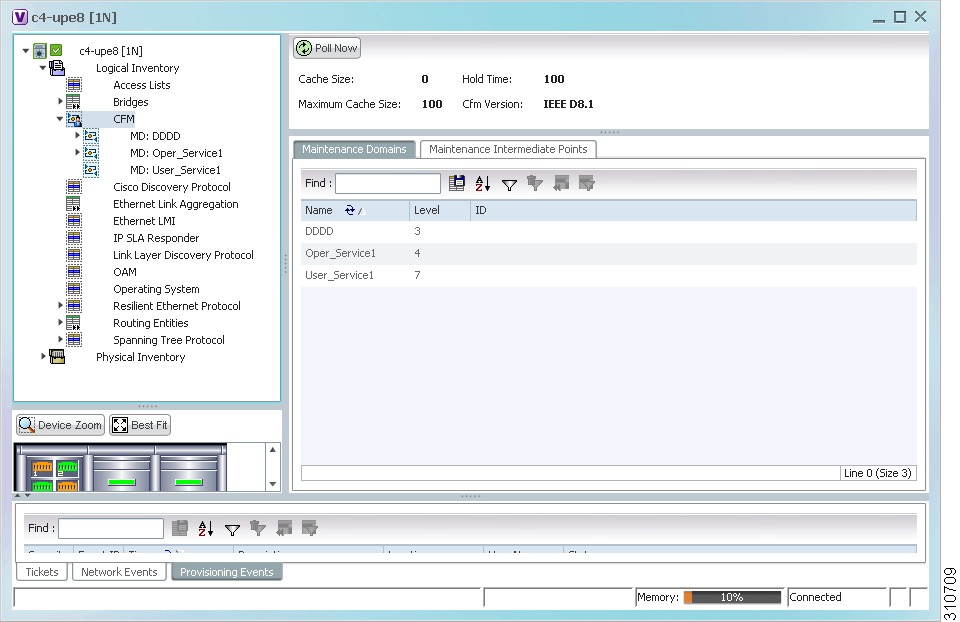
Figure 15-1 shows an example of CFM in logical inventory.

Figure 15-1 CFM in Logical Inventory

Table 15-3 describes the information displayed for CFM.

Table 15-3 CFM Properties 

Field
Description

Cache Size

CFM traceroute cache size in number of lines.

Hold Time

Configured hold time (in minutes) that is used to indicate to the receiver the validity of traceroute and loopback messages transmitted by the device. The default value is 2.5 times the transmit interval.

Maximum Cache Size

Maximum CFM traceroute cache size in number of lines.

CFM Version

CFM version, such as IEEE D8.1.

Maintenance Domains Table

Name

Domain name.

Level

Unique level the domain is managed on. Values range from 0 to 7.

ID

Optional domain identifier.


Step 3 Click the Maintenance Intermediate Points tab to view MIP information. See Figure 15-2.

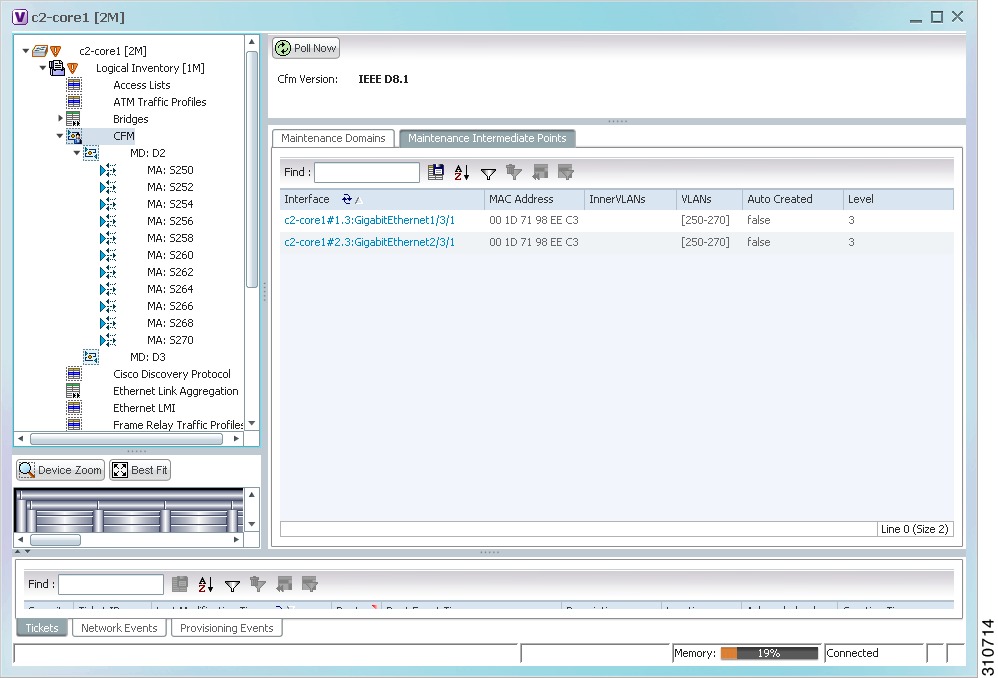
Figure 15-2 CFM Maintenance Intermediate Points Tab

Table 15-4 describes the information that is displayed in the Maintenance Intermediate Points table.

Table 15-4 CFM Maintenance Intermediate Point Properties 

Field
Description

Interface

Interface configured as a MIP, hyperlinked to its entry in physical inventory.

MAC Address

MAC address of the interface.

Inner VLANs

Inner VLAN identifiers.

VLANs

VLANs associated with the interface.

Auto Created

Whether or not the MIP was automatically created: True or False.

Level

Unique level the domain is managed on. Values range from 0 to 7.


Step 4 To view the details of a specific maintenance domain, do one of the following:

Choose Logical Inventory > CFM > domain.

Double-click the required entry in the Maintenance Domains table.

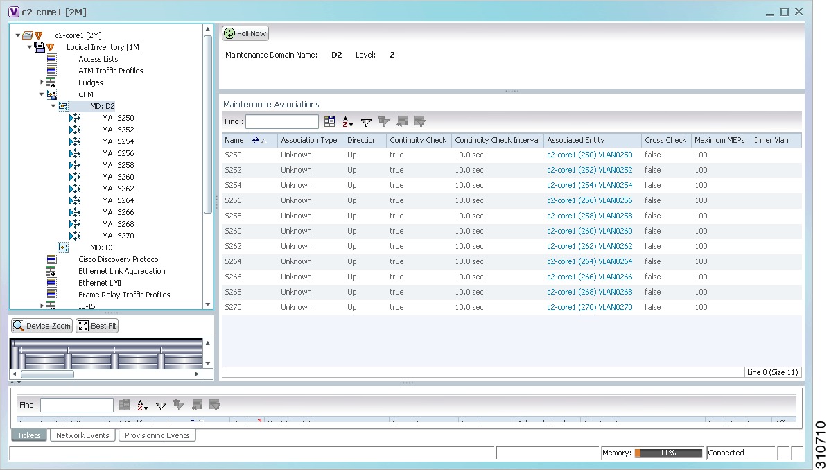
Figure 15-3 shows an example of the information displayed for the maintenance domain.

Figure 15-3 CFM Maintenance Domain Properties

Table 15-5 describes the information that is displayed for CFM maintenance domains.

Table 15-5 CFM Maintenance Domain Properties 

Field
Description

Maintenance Domain Name

Name of the domain.

Level

Level at which the domain is managed: 0-7.

ID

Optional maintenance domain identifier.

Maintenance Associations Table

Name

Name of the maintenance association.

Association Type

Maintenance association type.

Direction

Direction of the maintenance association: Up or Down.

Continuity Check

Whether or not the continuity check is enabled: True or False.

Continuity Check Interval

Interval (in seconds) for checking continuity.

Associated Entity

Bridge, port, or pseudowire that the maintenance association uses for CFM. Click the hyperlinked entry to view the item in inventory.

Cross Check

Whether or not cross checking is enabled: True or False.

Maximum MEPs

Maximum number of maintenance endpoints (MEPs) that can be configured on the maintenance association.

Inner VLAN

Inner VLAN identifier.


Step 5 To view the properties for a maintenance association's endpoints, do one of the following:

Choose Logical Inventory > CFM > domain > association.

In the Maintenance Associations table, double-click the required association.

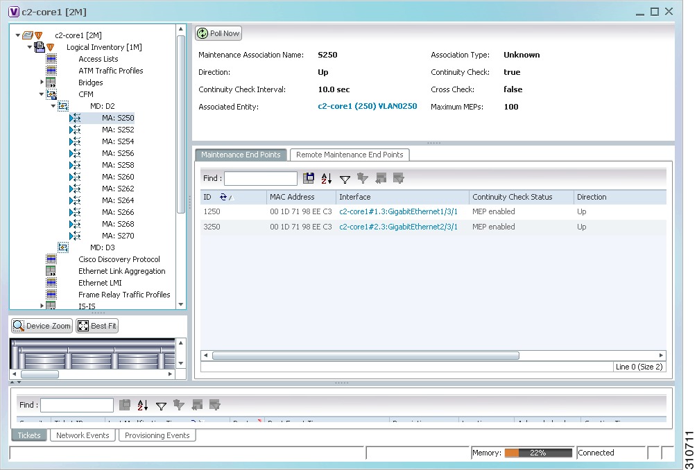
Figure 15-4 shows the information displayed for the maintenance association endpoints.

Figure 15-4 CFM Maintenance Association - Endpoint Properties

Table 15-6 describes the information that is displayed for CFM maintenance associations and MIPs.
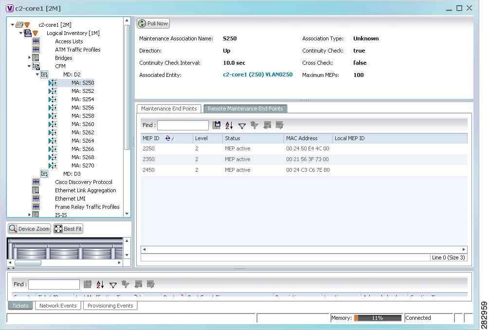
Table 15-6 CFM Maintenance Association Properties 

Field
Description

Maintenance Association Name

Name of the maintenance association.

Association Type

Maintenance association type, such as Bridge Domain.

Direction

Direction of the maintenance association: Up or Down.

Continuity Check

Whether or not the continuity check is enabled: True or False.

Continuity Check Interval

Interval (in seconds) for checking continuity.

Cross Check

Whether or not cross checking is enabled: True or False.

Associated Entity

Bridge that the maintenance association uses for CFM. Click the hyperlinked entry to view the bridge in logical inventory.

Maximum MEPs

Maximum number of MEPs that can be configured on the maintenance association.

Inner VLANs

Inner VLAN identifiers.

Maintenance End Points Table

ID

Local identifier for the MEP.

MAC Address

MAC address that identifies the MEP.

Interface

Interface on which the MEP is configured, hyperlinked to the respective EFP, VSI or interface in inventory.

Continuity Check Status

CFM continuity check status: MEP Active, MEP Inactive, MEP Enabled, MEP Disabled, or Unknown.

Direction

Direction of traffic on which the MEP is defined: Up, Down, or Unknown.


Step 6 Click the Remote Maintenance End Points tab to view the information displayed for remote MEPs. See Figure 15-5.

Figure 15-5 Remote Maintenance End Points Table

Table 15-7 describes the information presented for remote MEPs.

Table 15-7 CFM Remote Maintenance End Points Table 

Field
Description

MEP ID

Remote MEP identifier.

Level

Level at which the remote MEP is managed: 0-7.

Status

Status of the remote MEP, such as MEP Active.

MAC Address

MAC address of the remote MEP.

Local MEP ID

Numeric identifier assigned to the local MEP. Values range from 1 to 8191.

Note If the remote MEP is in Up mode, the remote MEP is not associated to the local MEP. As a result, the Local MEP ID column is empty.


Related Topics

Ethernet OAM Overview

Viewing Ethernet LMI Properties

Viewing Link OAM Properties

Viewing Ethernet LMI Properties

Ethernet Local Management Interface (LMI) is a protocol that operates between the customer edge (CE) network element and the provider edge (PE) network element.

Ethernet LMI:

Runs only on the PE-CE User Network Interface (UNI) link.

Notifies the CE of connectivity status and configuration parameters of Ethernet services available on the CE port.

Ethernet LMI interoperates with CFM, another OAM protocol that runs within the provider network, to collect OAM status. CFM runs at the provider maintenance level with inward-facing MEPs at the UNI. Using the OAM Ethernet infrastructure, Ethernet LMI works with CFM to provide end-to-end status of Ethernet virtual connections (EVCs) across CFM domains.

To view Ethernet LMI properties:


Step 1 In Prime Network Vision, double-click the device configured for Ethernet LMI.

Step 2 In the inventory window, choose Logical Inventory > Ethernet LMI.

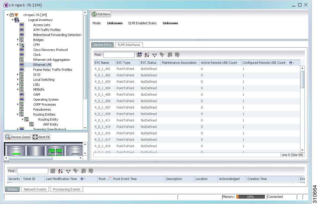
Figure 15-6 shows an example of Ethernet LMI properties in logical inventory.

Figure 15-6 Ethernet LMI in Logical Inventory

Table 15-8 describes the information displayed for Ethernet LMI.

Table 15-8 Ethernet LMI Properties in Logical Inventory 

Field
Description

Globally Enabled

Whether or not Ethernet LMI is enabled globally: True or False.

Mode

Ethernet LMI mode: CE or PE.

Device EVCs Tab

EVC Name

Name of the EVC.

EVC Type

Type of EVC: Point-to-point or Multipoint.

EVC Status

EVC status: Active, Inactive, Not Defined, or Partially Active.

Maintenance Association

Hyperlinked entry to the maintenance association in CFM in logical inventory. For more information about maintenance associations, see Table 15-6.

Active Remote UNI Count

Number of active remote UNIs.

Configured Remote UNI Count

Number of configured remote UNIs.

ELMI Interfaces Tab

Interface Name

Hyperlinked entry to the interface in physical inventory. For more information, see Step 4 in this procedure.

T391

Frequency at which the customer equipment sends status inquiries. The range is 5-30 seconds, with a default of 10 seconds.

T392

Frequency at which the metro Ethernet network verifies that status enquiries have been received. The range is 5-30 seconds, with a default of 15 seconds. A value of 0 (zero) indicates the timer is disabled.

N391

Frequency at which the customer equipment polls the status of the UNI and all EVCs. The range is 1-65000 seconds, with a default of 360 seconds.

N393

Error count for the metro Ethernet network. The range is 1-10, with a default of 4.
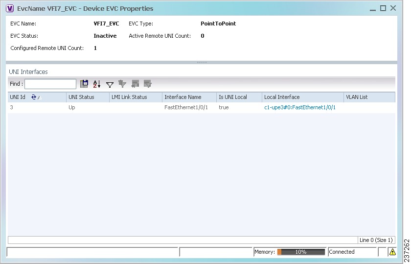

Step 3 To view device EVC properties, double-click an EVC name in the Device EVCs tab.

The Device EVC Properties window is displayed as shown in Figure 15-7.

Figure 15-7 Device EVC Properties Window

Table 15-9 describes the information displayed in the Device EVC Properties window.

Table 15-9 Device EVC Properties in Logical Inventory 

Field
Description

EVC Name

Name of the EVC.

EVC Type

Type of EVC: Point-to-point or Multipoint.

EVC Status

EVC status: Active, Inactive, Not Defined, or Partially Active.

Maintenance Association

Hyperlinked entry to the maintenance association in CFM in logical inventory. For more information about maintenance associations, see Table 15-6.

Active Remote UNI Count

Number of active remote UNIs.

Configured Remote UNI Count

Number of configured remote UNIs.

UNI Interfaces Table

UNI Id

UNI identifier.

UNI Status

Status of the UNI: Up or Down.

LMI Link Status

Status of the LMI link: Up or Down.

Interface Name

Interface on which UNI is configured.

Is UNI Local

Whether or not UNI is local: True or False.

Local Interface

Hyperlinked entry to the interface in physical inventory.

VLAN List

Name of the VLAN associated with the UNI interface.


Step 4 To view properties for an Ethernet LMI interface in physical interface, click the required interface name in the ELMI Interfaces table.

Table 15-10 describes the information displayed in the UNI Properties area in physical inventory.

Table 15-10 Ethernet LMI UNI Properties in Physical Inventory 

Field
Description

Service Multiplexing Enabled

Whether or not the interface is configured for UNI multiplexing: True or False.

Bundling Enabled

Whether or not the interface is configured for UNI bundling: True or False.

UNI Id

UNI identifier.

Bundling Type

Type of bundling applied: All-to-One or None.

This field appears only when a bundling type is set.


Related Topics

Ethernet OAM Overview

Viewing Connectivity Fault Management Properties

Viewing Link OAM Properties

Viewing Link OAM Properties

Link OAM is an optional sublayer implemented in the OSI Data Link Layer between the Logical Link Control and MAC sublayers.

The Link OAM frames, OAM Protocol Data Units (OAMPDUs), cannot propagate beyond a single hop within an Ethernet network. Link OAM processes include:

Discovery—Discovery is the first Link OAM process. During discovery, Link OAM identifies the devices at each end of the link and learns their OAM capabilities.

Link monitoring—Link OAM link monitoring includes:

Monitoring links and issuing notifications when error thresholds are exceeded or faults occur.

Collecting statistics on the number of frame errors (or percent of frames that have errors) and the number of coding symbol errors.

Remote MIB Variable Retrieval—Provides 802.3ah MIB polling and response (but not writing).

Remote Failure indication—Informs peers when a received path goes down. Because link connectivity faults caused by slowly deteriorating quality are difficult to detect, Link OAM communicates such failure conditions to its peer using OAMPDU flags. The failure conditions that can be communicated are a loss of signal in one direction on the link, an unrecoverable error (such as a power failure), or some other critical event.

Remote Loopback—Puts the peer device in (near-end) intrusive loopback mode using the OAMPDU loopback control. Statistics can be collected during the link testing. In loopback mode, every frame received is transmitted back unchanged on the same port (except for OAMPDUs, which are needed to maintain the OAM session). Loopback mode helps ensure the quality of links during installation or troubleshooting. Loopback mode can be configured so that the service provider device can put the customer device into loopback mode, but the customer device cannot put the service provider device in loopback mode.

Prime Network Vision supports topology discovery based on Link OAM information and enables you to view Link OAM properties.

To view Link OAM properties:


Step 1 In Prime Network Vision, double-click the device configured for Link OAM.

Step 2 In the inventory window, choose Logical Inventory > OAM.

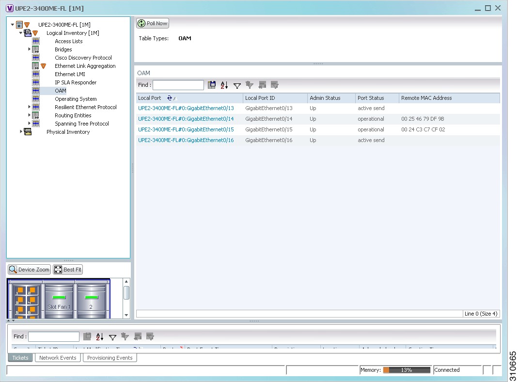
Figure 15-8 shows an example of Link OAM properties in logical inventory.

Figure 15-8 Link OAM Properties in Logical Inventory

Table 15-11 describes the information displayed for Link OAM.

Table 15-11 Link OAM Properties in Logical Inventory 

Field
Description

Table Types

Type of table. In this case, it is OAM.

OAM Table

Local Port

Name of the OAM-supported interface, hyperlinked to the location in physical inventory.

Local Port ID

Local port identifier, such as FastEthernet1/0/9.

Admin Status

Administrative status of the interface.

Port Status

Status of the port.

Remote MAC Address

Remote client MAC address.


Step 3 To view detailed information about an entry in the table, double-click the required entry.

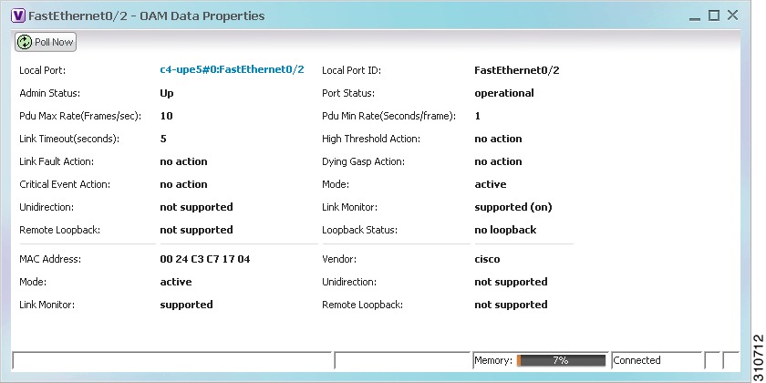
The Link OAM Data Properties window is displayed as shown in Figure 15-9.

Figure 15-9 Link OAM Data Properties Window

Table 15-12 describes the information that is displayed in the Link OAM Data Properties window.
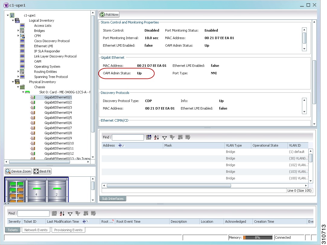
Table 15-12 Link OAM Data Properties Window 

Field
Description
Local Interface

Local Port

Name of the OAM-supported interface, hyperlinked to the location in physical inventory.

Local Port ID

Local port identifier.

Admin Status

Administrative status of the interface: Up or Down.

Port Status

Status of the port, such as Operational.

PDU Max Rate (Frames/sec)

Maximum transmission rate measured by the number of OAM PDUs per second; for example, 10 packets per second.

PDU Min Rate (Seconds/frame)

Minimum transmission rated measured by the number of seconds required for one OAM PDU; for example, 1 packet per 2 seconds.

Link Timeout

Number of seconds of inactivity on a link before the link is dropped.

High Threshold Action

Action that occurs when the high threshold for an error is exceeded.

Link Fault Action

Action that occurs when the signal is lost.

Dying Gasp Action

Action that occurs when an unrecoverable condition is encountered.

Critical Event Action

Action that occurs when an unspecified vendor-specific critical event occurs.

Mode

Mode of the interface: Active or Passive.

Unidirection

Status of unidirectional Ethernet on the local interface: Supported or Not supported.

Link Monitor

Status of link monitoring on the local interface: Supported or Not supported.

Remote Loopback

Status of remote loopback on the local interface: Supported or Not supported.

Loopback Status

Status of loopback on the local interface: Supported or No loopback.

Remote Client

MAC Address

MAC address for the remote client.

Vendor

Vendor of the remote client.

Mode

Mode of the remote client: Active or Passive.

Unidirection

Status of unidirectional Ethernet on the remote client interface: Supported or Not supported.

Link Monitor

Status of link monitoring on the remote client interface: Supported or Not supported.

Remote Loopback

Status of loopback on the remote client interface: Supported or Not supported.


Step 4 To view Link OAM status in physical inventory, choose Physical Inventory > chassis > slot > interface.

The Link OAM administrative status is displayed as shown in Figure 15-10.

Figure 15-10 Link OAM Administrative Status in Physical Inventory


Related Topics

Ethernet OAM Overview

Viewing Connectivity Fault Management Properties

Viewing Ethernet LMI Properties