-
Cisco Active Network Abstraction Fault Management User Guide, 3.6
-
Cisco ANA 3.6 Fault Management User Guide - PDF of Entire Book
-
Fault Management Overview
-
Fault Detection and Isolation
-
Cisco ANA Event Correlation and Suppression
-
Advanced Correlation Scenarios
-
Correlation Over Unmanaged Segments
-
Event and Alarm Configuration Parameters
-
Impact Analysis
-
Supported Service Alarms
-
Supported Traps and Syslogs
-
Event and Alarm Correlation Flow
-
 Feedback
Table Of Contents
Correlation Over Unmanaged Segments
Types of Unmanaged Networks Supported
Fault Correlation Across the Frame Relay or ATM or Ethernet Cloud
Correlation Over Unmanaged Segments
This chapter describes how Cisco ANA performs correlation decisions over unmanaged segments, namely, clouds.
•
Cloud VNE—Describes managing more than one network segment that interconnects with others, over another network segment which is not managed.
•
Cloud VNE
In some scenarios Cisco ANA is required to manage more than one network segment that interconnects with others over another network segment which is not managed. In such setups, faults on one device might be correlated to faults on another device that is located on the other side of the unmanaged segment of the network, or to unknown problems in the unmanaged segment itself.
A virtual cloud is used for representing unmanaged network segments. It represents the unmanaged segment of the network as a single device that the two managed segments of the network are connected to, and has that device simulate the workings of the unmanaged segment.
Virtual clouds support specific network setups. The types of unmanaged networks that are supported are:
•
•
•
Types of Unmanaged Networks Supported
This section describes the types of unmanaged networks that are supported when a VNE simulates an unmanaged segment of a network.
Note
Fault Correlation Across the Frame Relay or ATM or Ethernet Cloud
When a Layer 3 or Layer 2 event (for example, reachability problem, neighbor change, Frame Relay DLCI down, ATM PVC down) occurs, it triggers a flow along the physical and logical path modeled on the VNEs. This is done in order to correlate to the actual root cause of this fault. If the flow passes over a cloud along the path flow, it marks it as a potential root cause for the fault. If there is no other root cause found on the managed devices, then the cloud becomes the root cause. A ticket is then issued and the original event correlates to it.
Cloud Problem Alarm
For some events, when there is no root cause found, a special cloud problem alarm is created. These events are then correlated to the alarm. The cloud problem alarm has a major severity, and is automatically cleared after a delay.
Note
BGP neighbor down syslog
OSPF neighbor loss syslog
EIGRP router query to neighbors timeouted syslog
ipx 3 bad igrp sap syslog
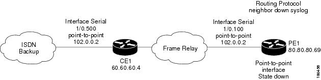
Cloud Correlation Example
In this example, two devices that have OSPF configured are connected through a cloud. A malfunction occurs inside the unmanaged network that causes the OPSF neighbor down alarm to be generated. In this case the OSPF neighbor down alarm is correlated to the cloud problem.
Figure 5-1 Cloud Correlation Example
On the PE1 device, the OSPF neighbor down alarm was received, and no root cause was detected in any of the managed devices. A disconnected link inside the unmanaged network caused the OSPF neighbor down alarm. The following alarms are generated and correlated:
•
–