-
Cisco Active Network Abstraction Fault Management User Guide, 3.6
-
Cisco ANA 3.6 Fault Management User Guide - PDF of Entire Book
-
Fault Management Overview
-
Fault Detection and Isolation
-
Cisco ANA Event Correlation and Suppression
-
Advanced Correlation Scenarios
-
Correlation Over Unmanaged Segments
-
Event and Alarm Configuration Parameters
-
Impact Analysis
-
Supported Service Alarms
-
Supported Traps and Syslogs
-
Event and Alarm Correlation Flow
-
 Feedback
Table Of Contents
Advanced Correlation Scenarios
IP Interface Failure Scenarios
IP Interface Status Down Alarm
Correlation of Syslogs and Traps
Ethernet, Fast Ethernet, Giga Ethernet Examples
ip interface status down Parameters
All ip interfaces down Parameters
Multi Route Correlation Example 1
Multi Route Correlation Example 2
Multi Route Correlation Example 3
Multi Route Correlation Example 4
Generic Routing Encapsulation (GRE) Tunnel Down/Up
GRE Tunnel Down Correlation Example 1
GRE Tunnel Down Correlation Example 2
Advanced Correlation Scenarios
This chapter describes the specific alarms which use advanced correlation logic on top of the root cause analysis flow:
•
Device Unreachable Alarm—Describes the device unreachable alarm, its correlation and provides various examples.
•
•
•
•
•
Device Unreachable Alarm
Connectivity Test
Connectivity tests are used to verify connectivity between the VNEs and managed network elements. The connectivity is tested using each protocol the VNE uses to poll the device. The supported protocols for connectivity tests are SNMP, Telnet and ICMP.
A device unreachable alarm will be issued if one or more of the connectivity test fails, that is, the device does not respond on this protocol. The alarm will be cleared when all the protocol connectivity test are passed successfully.
Note
Device Fault Identification
When a network element stops responding to queries from the management system, one of two things has happened:
•
•
Cisco ANA implements an algorithm that uses additional data to heuristically resolve the ambiguity and declare the root cause correctly. Refer to the following examples:
Device Unreachable Example 1
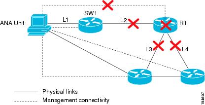
In this example, the router (R1) goes down. As a result the links, L2, L3, and L4 go down in addition to the R1 session.
Figure 4-1 Device Unreachable Example 1
In this case the system will provide the following report:
•
•
–
–
–
Device Unreachable Example 2
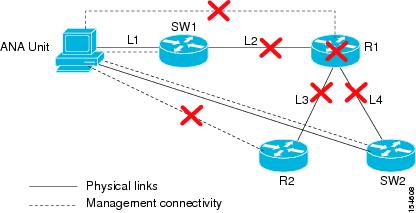
In this example, the router (R1) goes down. As a result the links, L2, L3, and L4 go down as well as the R1 session. The router R2, accessed by the link L3 is also unreachable.
Note
Figure 4-2 Device Unreachable Example 2
Note
In this case the system will provide the following report:
•
•
–
–
–
IP Interface Failure Scenarios
This section includes:
•
•
IP Interface Status Down Alarm
Alarms related to subinterfaces, for example, line-down trap, line-down syslog, and so on, are reported on IP interfaces configured above the relevant subinterface. This means that in the system, subinterfaces are represented by the IP interfaces configured above them. All events sourcing from subinterfaces without a configured IP are reported on the underlying Layer 1.
An "ip interface status down" alarm is generated when the status of the IP interfaces (whether it is over an interface or a subinterface) changes from up to down or any other non-operational state. All events sourced from the subinterfaces correlate to this alarm. In addition an "All ip interfaces down" alarm is generated when all the IP interfaces above a physical port change state to down.
The alarm's description includes the full name of the IP interface, for example Serial0.2 (including the identifier for the subinterface if it is a subinterface) and the source of the alarm source points to the IP interface (and not to Layer1).
All syslogs and traps indicating changes in subinterfaces (above which an IP is configured) correlate to the "ip interface status down" alarm (if this alarm was supposed to be issued). The source of these events is the IP interface. Syslogs and traps that indicate problems in Layer1 (that do not have a subinterface qualifier in their description) are sourced to Layer1.
Note
For example:
•
•
For events that occur on subinterfaces:
•
•
•
In case the main interface goes down, all related subinterfaces' traps and syslogs are correlated as child tickets to the main interface parent ticket.
The following technologies are supported:
•
•
•
•
•
Correlation of Syslogs and Traps
When receiving a trap or syslog for the subinterface level, immediate polling of the status of the relevant IP interface occurs and a polled parent event (for example, ip interface status down) is created. The trap or syslog is correlated to this alarm.
Where there is a multipoint setup and only some circuits under an IP interface go down, and this does not cause the state of the IP interface to change to down, then no "ip interface status down" alarm is created. All the circuit down syslogs correlate by flow to the possible root cause, for example, Device unreachable on a customer edge (CE) device.
All IP Interfaces Down Alarm
•
•
•
Note
The All ip interfaces down alarm is sourced to the Layer1 component. All alarms from "the other side", for example, device unreachable correlate to the All ip interfaces down alarm.
IP Interface Failure Examples
Note
If this is not the case, as in some Ethernet networks, and there is no change to the state of the IP interface, all the events on the subinterfaces that are capable of correlation flow will try to correlate to other possible root causes, including "cloud problem".
Interface Example 1
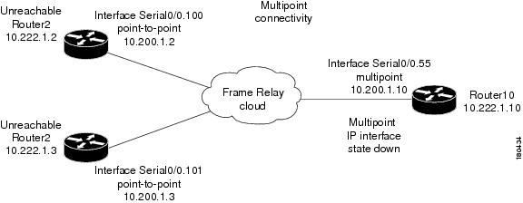
In this example there is multipoint connectivity between a PE and number of CEs through an unmanaged Frame Relay network. All the CEs (Router2 and Router3) have logical connectivity to the PE through a multipoint subinterface on the PE (Router10). The keep alive option is enabled for all circuits. A link is disconnected inside the unmanaged network that causes all the CEs to become unreachable.
Figure 4-3 Interface Example 1
The following failures are identified in the network:
•
•
The following correlation information is provided:
•
•
Interface Example 2
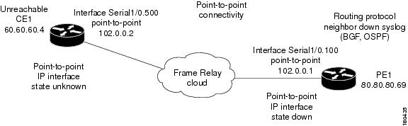
In this example there is point-to-point connectivity between a PE and a CE through an unmanaged Frame Relay network. CE1 became unreachable, and the status of the IP interface on the other side (on the PE1) changed state to down. The "keep alive" option is enabled. The interface is shut down between the unmanaged network and CE1.
Figure 4-4 Interface Example 2
The following failures are identified in the network:
•
•
The following correlation information is provided:
•
–
–
Interface Example 3
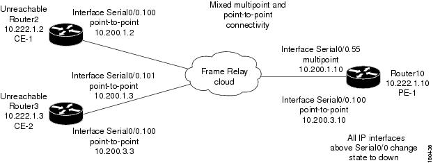
In this example there is a failure of multiple IP interfaces above the same physical port (mixed point-to-point and multipoint Frame Relay connectivity). CE1 (Router2) has a point-to-point connection to PE1 (Router10). CE1 and CE2 (Router3) have multipoint connections to PE1. The IP interfaces on PE1 that are connected to CE1, and CE2 are all configured above Serial0/0. The "keep alive" option is enabled. A link is disconnected inside the unmanaged network that has caused all the CEs to become unreachable.
Figure 4-5 Interface Example 3
The following failures are identified in the network:
•
•
The following correlation information is provided:
•
–
–
–
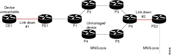
Interface Example 4
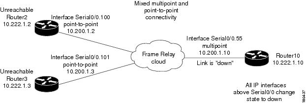
In this example there is a link down. In a situation where a link down occurs, whether it involves a cloud or not, the link failure is considered to be the most probable root cause for any other failures. In this example, a link is disconnected between the unmanaged network and the PE.
Figure 4-6 Interface Example 4
The following failures are identified in the network:
•
•
•
•
The following correlation information is provided:
•
•
•
•
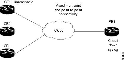
Interface Example 5
In this example on the PE1 device that has multipoint connectivity, one of the circuits under the IP interface has gone down and the CE1 device which is connected to it has become unreachable. The status of the IP interface has not changed and other circuits are still operational.
Figure 4-7 General Interface Example
The following failures are identified in the network:
•
•
The following correlation information is provided:
•
–
ATM Examples
Similar examples involving ATM technology have the same result, assuming that a failure in an unmanaged network causes the status of the IP interface to change to down (ILMI is enabled).
Ethernet, Fast Ethernet, Giga Ethernet Examples
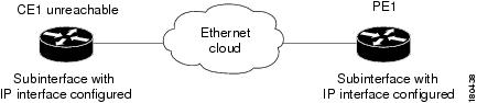
Interface Example 6
In this example there is an unreachable CE due to a failure in the unmanaged network.
Figure 4-8 Interface Example 6
The following failures are identified in the network:
•
•
The following correlation information is provided:
•
•
Interface Example 7
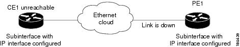
In this example there is a link down on the PE that results in the CE becoming unreachable.
Figure 4-9 Interface Example 7
The following failures are identified in the network:
•
•
•
The following correlation information is provided:
•
–
–
–
Interface Registry Parameters
ip interface status down Parameters
The following ip interface status down parameters can be controlled through the registry:
•
•
•
•
•
•
Note
All ip interfaces down Parameters
The following All ip interfaces down parameters can be controlled through the registry:
•
•
•
•
•
•
•
Note
Multi Route Correlation
The correlation mechanism supports multi route scenarios, thereby eliminating false correlation, and guaranteeing that the correct root cause alarm is reported.
The correlation mechanism ensures that if multi-route segments exist then all the alarms found on a certain path (after eliminating invalid paths) are collected into an alarm set. These alarm sets are input into a multi route filtering algorithm which eliminates irrelevant alarms from these sets, and outputs the potentially root cause alarms. The root-cause alarm is determined from this group.
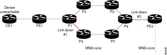
Multi Route Correlation Example 1
In this example, a link went down in the multi route segment between P1 and P4, and another link went down in the single route segment between P6 and PE2. As a result, CE1 lost connectivity to its management port, and became unreachable.
Figure 4-10 Multi Route Correlation Example 1
In this case the system will provide the following report:
•
Note
Multi Route Correlation Example 2
In this example, there are traffic engineering routes (RSVP) from router CE2, so that CE2 can reach P1 through only three possible paths, namely:
•
•
•
Several links went down, and as a result, router CE2 became unreachable.
Figure 4-11 Multi Route Correlation Example 2
In this case the system will provide the following report:
•
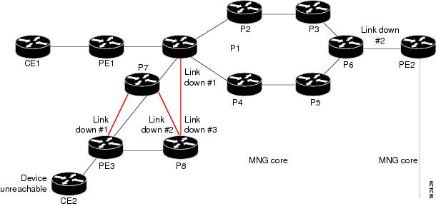
Multi Route Correlation Example 3
In this example, two paths exists from CE1 to PE2. Several links went down and as a result router CE1 became unreachable. In addition, router P4 is an unmanaged device.
Figure 4-12 Multi Route Correlation Example 3
In this case the system will provide the following report:
•
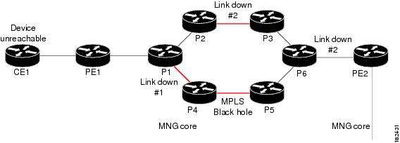
Multi Route Correlation Example 4
In this example, two paths exists from CE1 to PE2. Several links went down, and there is a MPLS black hole in the multi route segment. As a result router CE1 became unreachable.
Figure 4-13 Multi Route Correlation Example 4
In this case the system will provide the following report:
•
Generic Routing Encapsulation (GRE) Tunnel Down/Up
Generic Routing Encapsulation (GRE) is a tunneling protocol that encapsulates a variety of network layer packets inside IP tunneling packets, creating a virtual point-to-point link to devices at remote points over an IP network. It is used on the Internet to secure virtual private networks (VPNs). GRE encapsulates the entire original packet with a standard IP header and GRE header before the IPsec process. GRE can carry multicast and broadcast traffic, making it possible to configure a routing protocol for virtual GRE tunnels. The routing protocol detects loss of connectivity and reroutes packets to the backup GRE tunnel, thus providing high resiliency.
GRE is stateless, which means that the tunnel endpoints do not monitor the state or availability of other tunnel endpoints. This feature helps service providers support IP tunnels for clients, who don't know the service provider's internal tunneling architecture. It gives clients the flexibility of reconfiguring their IP architectures without worrying about connectivity.
GRE Tunnel Down/Up Alarm
When a GRE tunnel link exists, if the status of the IP interface of the GRE tunnel edge changes to down, a GRE Tunnel Down alarm is created. The IP Interface Down alarms of both sides of the link will correlate to the GRE Tunnel Down alarm. The GRE Tunnel Down alarm will initiate an IP based flow toward the GRE destination. If an alarm is found during the flow, it will correlate to it.
Note
When a failure occurs, the GRE tunnel link is marked orange. When the IP interface comes back up, a fixing alarm is sent, and the link is marked green. The GRE Tunnel Down alarm is cleared by a corresponding GRE Tunnel Up alarm. It will also be cleared when the GRE link is discovered again.
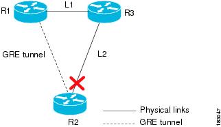
GRE Tunnel Down Correlation Example 1
The following provides an example of a GRE Tunnel Down correlation for a single GRE tunnel.
In this example:
•
•
•
Figure 4-14 GRE Tunnel Down Example 1 (Single GRE Tunnel)
When a Link Down occurs on L2, a Link Down alarm appears. A GRE Tunnel Down alarm is issued as the IP interfaces of the tunnel edge devices go down. The IP Interface Status Down alarms will correlate to the GRE Tunnel Down alarm. The GRE tunnel down will correlate to the Link Down alarm.
The system provides the following report:
•
•
GRE tunnel down Router1:tunnel <-> Router 2:tunnel
–
–
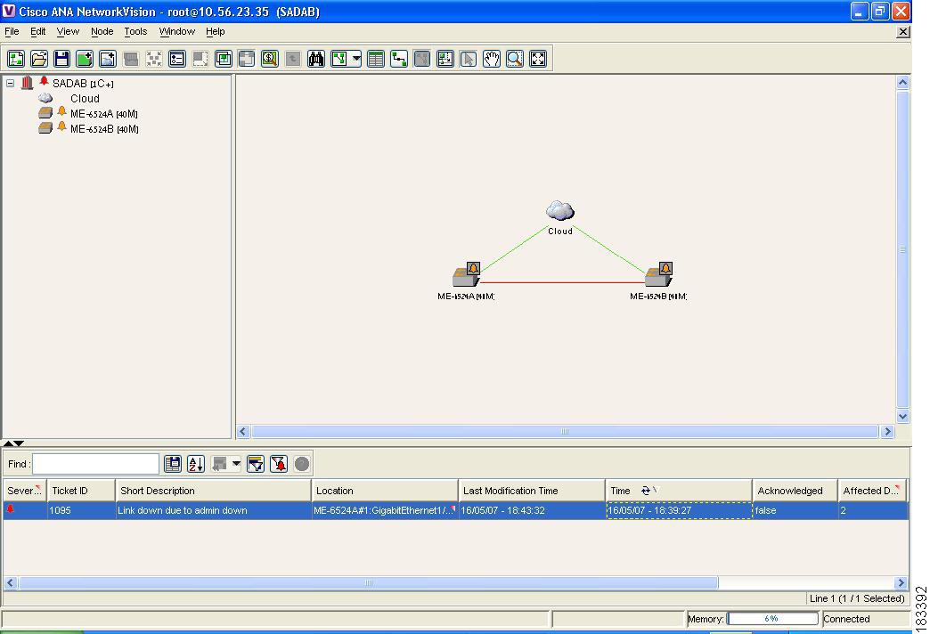
GRE Tunnel Down Correlation Example 2
This example provides a real world scenario, whereby multiple GRE tunnels cross through a physical link. When this link is shut down by an administrator, many alarms are generated. All the alarms are correlated to the root cause ticket "Link down due to admin down", as illustrated in Figure 4-15.
Figure 4-15 GRE Tunnel Down Example 2 (Multiple GRE Tunnels)
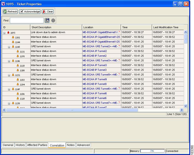
Figure 4-16 shows the Correlation tab of the Ticket Properties dialog box, which displays all the alarms that are correlated to the ticket, including the correlation for each GRE tunnel and its interface status.
Figure 4-16 Alarms Correlation to GRE Tunnel Down Ticket
As illustrated, the system provides the following report:
•
•
GRE tunnel down ME-6524AGRE:Tunnel2 <-> ME-6524B GRE:Tunnel2
–
–
GRE tunnel down ME-6524AGRE:Tunnel3 <-> ME-6524B GRE:Tunnel3
–
–
etc.
BGP Process Down Alarm
The BGP process down alarm is issued when the BGP process is shut down on a device. If a BGP process is shutdown on a device, the BGP neighbor down events will correlate to it as well as all the device unreachable alarms from the CE devices that lost connectivity to the VRF due to the BGP process down on the route reflector. The syslogs that the device issues expedite the status check of the BGP process and BGP neighbors.
MPLS Interface Removed Alarm
The MPLS interface removed alarm is issued when a MPLS IP interface is removed and there is no MPLS TE tunnel on the same interface. In addition, this may lead to two black holes on either side and MPLS black hole found alarms may be issued. The black holes will send a flood message to the PEs and check for any broken LSPs, and broken LSP discovered alarms may be issued. The MPLS black hole found and broken LSP discovered alarms are correlated to the MPLS interface removed alarm. The syslogs that the device issues expedite the status check of the label switching table and MPLS status.