-
Performance Routing Configuration Guide, Cisco IOS XE Release 3S
-
Configuring Basic Performance Routing
-
Performance Routing Border Router Only Functionality
-
Understanding Performance Routing
-
Configuring Advanced Performance Routing
-
BGP Inbound Optimization Using Performance Routing
-
Configuring Performance Routing Cost Policies
-
PfR Data Export v1.0 NetFlow v9 Format
-
Using Performance Routing to Control EIGRP Routes with mGRE DMVPN Hub-and-Spoke Support
-
Performance Routing Link Groups
-
Performance Routing with NAT
-
Performance Routing with NBAR CCE Application Recognition
-
Performance Routing - Protocol Independent Route Optimization (PIRO)
-
PfR RSVP Control
-
PfR Scaling Improvement for Application Traffic Class
-
PfR Simplification Phase 1
-
PfR SNMP MIB v1.0 (Read Only)
-
PfR SNMP Traps v1.0
-
Static Application Mapping Using Performance Routing
-
PfR Target Discovery v1.0
-
PfR Bandwidth Visibility Distribution for xDSL Access
-
Performance Routing Traceroute Reporting
-
PfR Voice Traffic Optimization Using Active Probes
-
 Feedback
Contents
- PfR Voice Traffic Optimization Using Active Probes
- Finding Feature Information
- Prerequisites for PfR Voice Traffic Optimization Using Active Probes
- Information About PfR Voice Traffic Optimization Using Active Probes
- Voice Quality on IP Networks
- Probes Used by PfR
- PfR Voice Traffic Optimization Using Active Probes
- PfR Voice Performance Metrics
- PfR Active Probe Forced Target Assignment
- How to Configure PfR Voice Traffic Optimization Using Active Probes
- Identifying Traffic for PfR Using a Prefix List
- Identifying Voice Traffic to Optimize Using an Access List
- Configuring PfR Voice Probes with a Target Assignment
- Configuration Examples for PfR Voice Traffic Optimization Using Active Probes
- Example Optimizing Only Voice Traffic Using Active Probes
- Example Optimizing Traffic (Including Voice Traffic) Using Active Probes
- Additional References
- Feature Information for PfR Voice Traffic Optimization Using Active Probes
PfR Voice Traffic Optimization Using Active Probes
This module documents a Performance Routing (PfR) solution that supports outbound optimization of voice traffic based on the voice metrics, jitter and Mean Opinion Score (MOS). Jitter and MOS are important quantitative quality metrics for voice traffic and these voice metrics are measured using PfR active probes.
PfR provides automatic route optimization and load distribution for multiple connections between networks. PfR is an integrated Cisco IOS solution that allows you to monitor IP traffic flows and then define policies and rules based on prefix performance, link load distribution, link bandwidth monetary cost, and traffic type. PfR provides active and passive monitoring systems, dynamic failure detection, and automatic path correction. Deploying PfR enables intelligent load distribution and optimal route selection in an enterprise network.
- Finding Feature Information
- Prerequisites for PfR Voice Traffic Optimization Using Active Probes
- Information About PfR Voice Traffic Optimization Using Active Probes
- How to Configure PfR Voice Traffic Optimization Using Active Probes
- Configuration Examples for PfR Voice Traffic Optimization Using Active Probes
- Additional References
- Feature Information for PfR Voice Traffic Optimization Using Active Probes
Finding Feature Information
Your software release may not support all the features documented in this module. For the latest feature information and caveats, see the release notes for your platform and software release. To find information about the features documented in this module, and to see a list of the releases in which each feature is supported, see the Feature Information Table at the end of this document.
Use Cisco Feature Navigator to find information about platform support and Cisco software image support. To access Cisco Feature Navigator, go to www.cisco.com/go/cfn. An account on Cisco.com is not required.
Prerequisites for PfR Voice Traffic Optimization Using Active Probes
Before implementing PfR optimization for voice traffic, you need to understand an overview of how PfR works and how to set up PfR network components. See the Understanding Performance Routing, Configuring Basic Performance Routing, and Configuring Advanced Performance Routing modules for more details.
Information About PfR Voice Traffic Optimization Using Active Probes
- Voice Quality on IP Networks
- Probes Used by PfR
- PfR Voice Traffic Optimization Using Active Probes
- PfR Voice Performance Metrics
- PfR Active Probe Forced Target Assignment
Voice Quality on IP Networks
Voice packets traveling through an IP network are no different from data packets. In the plain old telephone system (POTS), voice traffic travels over circuit-switched networks with predetermined paths and each phone call is given a dedicated connection for the duration of the call. Voice traffic using POTS has no resource contention issues, but voice traffic over an IP network has to contend with factors such as delay, jitter, and packet loss, which can affect the quality of the phone call.
Delay
Delay (also referred as latency) for voice packets is defined as the delay between when the packet was sent from the source device and when it arrived at a destination device. Delay can be measured as one-way delay or round-trip delay. The largest contributor to latency is caused by network transmission delay. Round-trip delay affects the dynamics of conversation and is used in Mean Opinion Score (MOS) calculations. One-way delay is used for diagnosing network problems. A caller may notice a delay of 200 milliseconds and try to speak just as the other person is replying because of packet delay. The telephone industry standard specified in ITU-T G.114 recommends the maximum desired one-way delay be no more than 150 milliseconds. Beyond a one-way delay of 150 milliseconds, voice quality is affected. With a round-trip delay of 300 milliseconds or more, users may experience annoying talk-over effects.
Jitter
Jitter means interpacket delay variance. When multiple packets are sent consecutively from source to destination, for example, 10 ms apart, and if the network is behaving ideally, the destination should be receiving them 10 ms apart. But if there are delays in the network (like queuing, arriving through alternate routes, and so on) the arrival delay between packets might be greater than or less than 10 ms. Using this example, a positive jitter value indicates that the packets arrived more than 10 ms apart. If the packets arrive 12 ms apart, then positive jitter is 2 ms; if the packets arrive 8 ms apart, then negative jitter is 2 ms. For delay-sensitive networks like VoIP, positive jitter values are undesirable, and a jitter value of 0 is ideal.
Packet Loss
Packet loss can occur due an interface failing, a packet being routed to the wrong destination, or congestion in the network. Packet loss for voice traffic leads to the degradation of service in which a caller hears the voice sound with breaks. Although average packet loss is low, voice quality may be affected by a short series of lost packets.
Mean Opinion Score (MOS)
With all the factors affecting voice quality, many people ask how voice quality can be measured. Standards bodies like the ITU have derived two important recommendations: P.800 (MOS) and P.861 (Perceptual Speech Quality Measurement [PSQM]). P.800 is concerned with defining a method to derive a Mean Opinion Score of voice quality. MOS scores range between 1 representing the worst voice quality, and 5 representing the best voice quality. A MOS of 4 is considered “toll-quality” voice.
Probes Used by PfR
PfR uses some of the IP SLA probes to help gather the data PfR requires to make its decisions.
Cisco IOS IP SLAs
Cisco IOS IP SLAs are an embedded feature set in Cisco IOS software and they allow you to analyze IP service levels for IP applications and services, to increase productivity, to lower operational costs, and to reduce occurrences of network congestion or outages. IP SLAs use active traffic monitoring--the generation of traffic in a continuous, reliable, and predictable manner--for measuring network performance. The accuracy of measured data is enhanced by enabling the IP SLAs Responder, available in Cisco routers, on the destination device. For more details about IP SLAs, see the Cisco IOS IP SLAs Configuration Guide .
Active Probe Types Used by PfR
The following types of active probes can be configured:
ICMP Echo--A ping is sent to the target address. PfR uses ICMP Echo probes, by default, when an active probe is automatically generated. Configuring an ICMP echo probe does not require knowledgeable cooperation from the target device. However, repeated probing could trigger an Intrusion Detection System (IDS) alarm in the target network. If an IDS is configured in a target network that is not under your control, we recommend that you notify the administrator of this target network.
Jitter--A jitter probe is sent to the target address. A target port number must be specified. A remote responder must be enabled on the target device, regardless of the configured port number.
TCP Connection--A TCP connection probe is sent to the target address. A target port number must be specified. A remote responder must be enabled if TCP messages are configured to use a port number other than TCP port number 23, which is well-known.
UDP Echo--A UDP echo probe is sent to the target address. A target port number must be specified. A remote responder must be enabled on the target device, regardless of which port number is configured.
Probe Frequency
The frequency of an active probe used by PfR is set by default to 60 seconds, but the frequency can be increased for each policy by configuring a lower time-interval between two probes. Increased probe frequency can reduce the response time and provide a better approximation of the MOS-low count percentage.
PfR Voice Traffic Optimization Using Active Probes
Configuring PfR to optimize voice traffic using active probes involves several decisions and subsequent branching tasks. The first step is to identify the traffic to be optimized and decide whether to use a prefix list or an access list. Use a prefix list to identify all traffic, including voice traffic, with a specific set of destination prefixes. Use an access list to identify only voice traffic with a specific destination prefix and carried over a specific protocol.
The second step in optimizing voice traffic is to configure active probing using the active-probe or set active-probe command to specify the type of active probe to be used. PfR also provides the ability to set a forced target assignment for the active probe.
The final step in optimizing voice traffic is to configure a PfR policy to set the performance metrics that you want PfR to apply to the identified traffic.
PfR Voice Performance Metrics
PfR voice traffic optimization provides support for outbound optimization of voice traffic on the basis of the voice performance metrics, delay, packet loss, jitter, and MOS. Delay, packet loss, jitter and MOS are important quantitative quality metrics for voice traffic, and these voice metrics are measured using PfR active probes. The IP SLA jitter probe is integrated with PfR to measure jitter (source to destination) and the MOS score in addition to measuring delay and packet loss. The jitter probe requires a responder on the remote side just like the UDP Echo probe. Integration of the IP SLA jitter probe type in PfR enhances the ability of PfR to optimize voice traffic. PfR policies can be configured to set the threshold and priority values for the voice performance metrics: delay, packet loss, jitter, and MOS.
Configuring a PfR policy to measure jitter involves configuring only the threshold value and not relative changes (used by other PfR features) because for voice traffic, relative jitter changes have no meaning. For example, jitter changes from 5 milliseconds to 25 milliseconds are just as bad in terms of voice quality as jitter changes from 15 milliseconds to 25 milliseconds. If the short-term average (measuring the last 5 probes) jitter is higher than the jitter threshold, the prefix is considered out-of-policy due to jitter. PfR then probes all exits, and the exit with the least jitter is selected as the best exit.
MOS policy works in a different way. There is no meaning to average MOS values, but there is meaning to the number of times that the MOS value is below the MOS threshold. For example, if the MOS threshold is set to 3.85 and if 3 out of 10 MOS measurements are below the 3.85 MOS threshold, the MOS-low-count is 30 percent. In the output of the show commands the field, ActPMOS, shows the number of actively monitored MOS packets with a percentage below threshold. If some of the MOS measurements are only slightly below the threshold, with percentage rounding, an ActPMOS value of zero may be displayed. When PfR runs a policy configured to measure MOS, both the MOS threshold value and the MOS-low-count percentage are considered. A prefix is considered out-of-policy if the short term (average over the last 5 probes) MOS-low-count percentage is greater than the configured MOS-low-count percentage. PfR then probes all exits, and the exit with the highest MOS value is selected as the best exit.
PfR Active Probe Forced Target Assignment
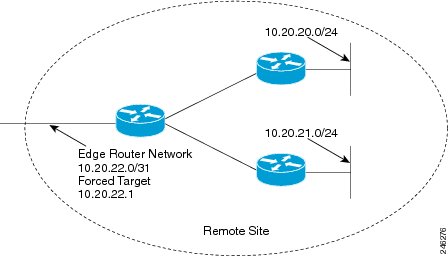
In earlier releases of the OER technology, the PfR active probe target is assigned to the longest matched prefix. There are some scenarios where you may want to use a target that does not match the destination prefix. The example in the figure below explains a scenario in which configuring a PfR forced target assignment is more appropriate than using the longest match prefix.
In the figure above we want to probe IP address 10.20.22.1 (at the edge of the network) for either network 10.20.21.0/24 or 10.20.22.0/24. Jitter is less likely to be introduced within the network so probing the edge of the network gives a measurement that is close to probing the final destination.
Forced target assignment allows you to assign a target to a group of prefixes or an application, even if they are not the longest match prefixes. Assigning a target can determine the true delay to the edge of a network rather than delay to an end host.
How to Configure PfR Voice Traffic Optimization Using Active Probes
Perform one of the first two optional tasks, depending on whether you want to use a prefix list or an access list to identify the traffic to be optimized. The third task can be used with traffic identified using an access list, and it also demonstrates how to use a forced target assignment. For an example configuration that can be used with traffic identified using a prefix list, see the “Example: Optimizing Traffic (Including Voice Traffic) Using Active Probes” section.
- Identifying Traffic for PfR Using a Prefix List
- Identifying Voice Traffic to Optimize Using an Access List
- Configuring PfR Voice Probes with a Target Assignment
Identifying Traffic for PfR Using a Prefix List
SUMMARY STEPSBefore traffic can be measured using PfR, it must be identified. Perform this task to use a prefix list to identify the traffic that PfR will probe.
1. enable
2. configure terminal
3. ip prefix-list list-name [seq seq-value] {deny network/length| permit network/length}
4. exit
DETAILED STEPSIdentifying Voice Traffic to Optimize Using an Access List
SUMMARY STEPSBefore voice traffic can be measured, it must be identified. Perform this task to use an access list to identify the voice traffic.
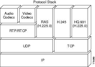
Voice traffic uses a variety of protocols and streams on the underlying IP network. The figure below is a representation of the protocol options available for carrying voice traffic over IP. Most signaling traffic for voice is carried over TCP. Most voice calls are carried over User Datagram Protocol (UDP) and Real-Time Transport Protocol (RTP). You can configure your voice devices to use a specific range of destination port numbers over UDP to carry voice call traffic.
1. enable
2. configure terminal
3. ip access-list {standard | extended} access-list-name
4. [sequence-number] permit udp source source-wildcard [operator [port]] destination destination-wildcard [operator [port]] [precedence precedence] [tos tos] [ttl operator value] [log] [time-range time-range-name] [fragments]
5. exit
DETAILED STEPSConfiguring PfR Voice Probes with a Target Assignment
After identifying the traffic (in this example, voice traffic identified using an access list) to be optimized, perform this task to configure the PfR jitter probes and assign the results of the jitter probes to optimize the identified traffic. In this task, the PfR active voice probes are assigned a forced target for PfR instead of the usual longest match assigned target. Before configuring the PfR jitter probe on the source device, the IP SLAs Responder must be enabled on the target device (the operational target). The IP SLAs Responder is available only on Cisco IOS software-based devices. Start this task at the network device that runs the IP SLAs Responder.
NoteThe device that runs the IP SLAs Responder does not have to be configured for PfR.
NotePolicies applied in a PfR map do not override global policy configurations.
Before You BeginSUMMARY STEPSBefore configuring this task, perform the Identifying Voice Traffic to Optimize Using an Access List task.
1. enable
2. configure terminal
3. ip sla monitor responder
4. exit
5. Move to the network device that is the PfR master controller.
6. enable
7. configure terminal
8. pfr-map map-name sequence-number
9. match ip address {access-list access-list-name| prefix-list prefix-list-name}
10. set active-probe probe-type ip-address [target-port number] [codec codec-name]
11. set probe frequency seconds
12. set jitter threshold maximum
13. set mos {threshold minimum percent percent}
14. set resolve {cost priority value | delay priority value variance percentage | jitter priority value variance percentage | loss priority value variance percentage | mos priority value variance percentage | range priority value | utilization priority value variance percentage}
15. set resolve mos priority value variance percentage
16. set delay {relative percentage | threshold maximum}
17. exit
18. pfr master
19. policy-rules map-name
20. end
21. show pfr master active-probes [appl| forced]
22. show pfr master policy {sequence-number|policy-name | default}
DETAILED STEPSExamples
This example shows output from the show pfr master active-probes forced command. The output is filtered to display only connection and status information about the active probes generated for voice traffic configured with a forced target assignment.
Router# show pfr master active-probes forced
OER Master Controller active-probes
Border   = Border Router running this Probe
Policy   = Forced target is configure under this policy
Type     = Probe Type
Target   = Target Address
TPort    = Target Port
N - Not applicable
The following Forced Probes are running:
Border          State    Policy             Type     Target          TPort
10.20.20.2     ACTIVE    40                 jitter   10.20.22.1      3050
10.20.21.3     ACTIVE    40                 jitter   10.20.22.4      3050
Configuration Examples for PfR Voice Traffic Optimization Using Active Probes
- Example Optimizing Only Voice Traffic Using Active Probes
- Example Optimizing Traffic (Including Voice Traffic) Using Active Probes
Example Optimizing Only Voice Traffic Using Active Probes
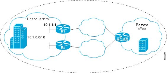
The figure below shows that voice traffic originating at the remote office and terminating at the headquarters has to be optimized to select the best path out of the remote office network. Degradation in voice (traffic) quality is less likely to be introduced within the network, so probing the edge of the network gives a measurement that is close to probing the final destination.
This configuration optimizes voice traffic to use the best performance path, whereas all other traffic destined to the same network--10.1.0.0/16--will follow the best path as indicated by a traditional routing protocol, for example BGP, that is configured on the device. As part of this optimization, PfR will use policy based routing (PBR) to set the best exit link for voice traffic within a device.
The following configuration is performed on the edge router R1 in the figure above in the headquarters network to enable the IP SLAs Responder.
enable
configure terminal
 ip sla responder
 exit
The following configuration is performed on the edge router MC/BR (which is both a PfR master controller and border router) in the figure above in the remote office network to optimize voice traffic using active probes.
enable
configure terminal
ip access-list extended Voice_Traffic
 10 permit udp any 10.1.0.0 0.0.255.255 range 16384 32767
 exit
pfr-map Voice_MAP 10
 match ip address access-list Voice_Traffic
 set active-probe jitter 10.1.1.1 target-port 1025 codec g711alaw
 set delay threshold 300
 set mos threshold 3.76 percent 30
 set jitter threshold 15
 set loss relative 5
 resolve mos priority 1
 resolve jitter priority 2
 resolve delay priority 3
 resolve loss priority 4
Example Optimizing Traffic (Including Voice Traffic) Using Active Probes
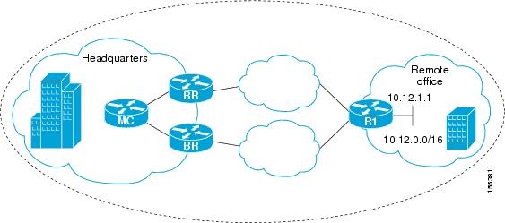
The figure below shows that traffic originating in the headquarters network and destined for the remote office network has to be optimized based on voice traffic metrics. Voice traffic is one of the most important traffic classes that travel from the headquarters to the remote office network, so the voice traffic must be prioritized to be optimized. Degradation in voice packet quality is less likely to be introduced within the network, so probing the edge of the network gives a measurement that is close to probing the final destination.
This configuration optimizes all traffic, including voice traffic, destined for the 10.12.0.0/16 network. The PfR optimization is based on the measurement of voice performance metrics with thresholding values using active probes. As part of the optimization, PfR will introduce a BGP or a static route into the headquarters network. For more details about BGP and static route optimization, see the “Understanding Performance Routing” module.
The following configuration is performed on router R1 in the figure above in the remote office network to enable the IP SLAs Responder.
enable
configure terminal
 ip sla responder
 exit
The following configuration is performed on one of the BR routers in the figure above in the headquarters network to optimize all traffic (including voice traffic) using active probes.
enable
configure terminal
 ip prefix-list All_Traffic_Prefix permit 10.12.0.0/16
 pfr-map Traffic_MAP 10
 match ip address prefix-list All_Traffic_Prefix
 set active-probe jitter 10.12.1.1 target-port 1025 codec g711alaw
! port 1025 for the target probe is an example.
 set delay threshold 300
 set mos threshold 3.76 percent 30
 set jitter threshold 15
 set loss relative 5
 resolve mos priority 1
 resolve jitter priority 2
 resolve delay priority 3
 resolve loss priority 4
Additional References
Related Documents
Related Topic
Document Title
Cisco IOS commands
Cisco IOS PfR commands: complete command syntax, command mode, command history, defaults, usage guidelines, and examples
Basic PfR configuration for Cisco IOS XE releases
“Configuring Basic Performance Routing” module
Information about configuration for the border router only functionality for Cisco IOS XE Releases 3.1 and 3.2
“Performance Routing Border Router Only Functionality” module
Concepts required to understand the Performance Routing operational phases for Cisco IOS XE releases
“Understanding Performance Routing” module
Advanced PfR configuration for Cisco IOS XE releases
“Configuring Advanced Performance Routing” module
IP SLAs overview
“Cisco IOS IP SLAs Overview” module
PfR home page with links to PfR-related content on our DocWiki collaborative environment
MIBs
Technical Assistance
Description
Link
The Cisco Support and Documentation website provides online resources to download documentation, software, and tools. Use these resources to install and configure the software and to troubleshoot and resolve technical issues with Cisco products and technologies. Access to most tools on the Cisco Support and Documentation website requires a Cisco.com user ID and password.
Feature Information for PfR Voice Traffic Optimization Using Active Probes
The following table provides release information about the feature or features described in this module. This table lists only the software release that introduced support for a given feature in a given software release train. Unless noted otherwise, subsequent releases of that software release train also support that feature.
Use Cisco Feature Navigator to find information about platform support and Cisco software image support. To access Cisco Feature Navigator, go to www.cisco.com/go/cfn. An account on Cisco.com is not required.
Table 1 Feature Information for PfR Voice Traffic Optimization Using Active Probes Feature Name
Releases
Feature Information
PfR Voice Traffic Optimization
Cisco IOS XE Release 3.3S
The PfR Voice Traffic Optimization feature provides support for outbound optimization of voice traffic based on the voice metrics, jitter and Mean Opinion Score (MOS). Jitter and MOS are important quantitative quality metrics for voice traffic and these voice metrics are measured using PfR active probes.
The following commands were introduced or modified by this feature: active-probe (PfR), jitter (PfR), mos (PfR), resolve (PfR), set active-probe (PfR), set jitter (PfR), set mos (PfR), set probe (PfR), set resolve (PfR), show pfr master active-probes, show pfr master policy, and show pfr master prefix.