-
Performance Routing Configuration Guide, Cisco IOS XE Release 3S
-
Configuring Basic Performance Routing
-
Performance Routing Border Router Only Functionality
-
Understanding Performance Routing
-
Configuring Advanced Performance Routing
-
BGP Inbound Optimization Using Performance Routing
-
Configuring Performance Routing Cost Policies
-
PfR Data Export v1.0 NetFlow v9 Format
-
Using Performance Routing to Control EIGRP Routes with mGRE DMVPN Hub-and-Spoke Support
-
Performance Routing Link Groups
-
Performance Routing with NAT
-
Performance Routing with NBAR CCE Application Recognition
-
Performance Routing - Protocol Independent Route Optimization (PIRO)
-
PfR RSVP Control
-
PfR Scaling Improvement for Application Traffic Class
-
PfR Simplification Phase 1
-
PfR SNMP MIB v1.0 (Read Only)
-
PfR SNMP Traps v1.0
-
Static Application Mapping Using Performance Routing
-
PfR Target Discovery v1.0
-
PfR Bandwidth Visibility Distribution for xDSL Access
-
Performance Routing Traceroute Reporting
-
PfR Voice Traffic Optimization Using Active Probes
-
 Feedback
Contents
- Performance Routing Link Groups
- Finding Feature Information
- Information About Performance Routing Link Groups
- Performance Routing Link Grouping
- How to Configure Performance Routing Link Groups
- Implementing Performance Routing Link Groups
- Configuration Examples for Performance Routing Link Groups
- Example Implementing Performance Routing Link Groups
- Additional References
- Feature Information for Performance Routing Link Groups
Performance Routing Link Groups
The Performance Routing - Link Groups feature introduced the ability to define a group of exit links as a preferred set of links, or a fallback set of links for Performance Routing (PfR) to use when optimizing traffic classes specified in a PfR policy.
- Finding Feature Information
- Information About Performance Routing Link Groups
- How to Configure Performance Routing Link Groups
- Configuration Examples for Performance Routing Link Groups
- Additional References
- Feature Information for Performance Routing Link Groups
Finding Feature Information
Your software release may not support all the features documented in this module. For the latest feature information and caveats, see the release notes for your platform and software release. To find information about the features documented in this module, and to see a list of the releases in which each feature is supported, see the Feature Information Table at the end of this document.
Use Cisco Feature Navigator to find information about platform support and Cisco software image support. To access Cisco Feature Navigator, go to www.cisco.com/go/cfn. An account on Cisco.com is not required.
Information About Performance Routing Link Groups
Performance Routing Link Grouping
The Performance Routing Link Groups feature introduced the ability to define a group of exit links as a preferred set of links, or a fallback set of links for PfR to use when optimizing traffic classes specified in an PfR policy. PfR currently selects the best link for a traffic class based on the preferences specified in a policy and the traffic class performance—using parameters such as reachability, delay, loss, jitter or MOS—on a path out of the specified link. Bandwidth utilization, cost, and the range of links can also be considered in selecting the best link. Link grouping introduces a method of specifying preferred links for one or more traffic classes in an PfR policy so that the traffic classes are routed through the best link from a list of preferred links, referred to as the primary link group. A fallback link group can also be specified in case there are no links in the primary group that satisfy the specified policy and performance requirements. If no primary group links are available, the traffic classes are routed through the best link from the fallback group. To identify the best exit, PfR probes links from both the primary and fallback groups.
Primary and fallback link groups can be configured at the master controller and are identified using a unique name. Link groups provide a method of grouping links such as high bandwidth links to be used, for example, by video traffic, by configuring an PfR policy to specify that the best link is to be selected from the link group that consists of only high bandwidth links. The traffic classes specified in a policy can be configured with only one primary link group and one fallback link group. The priority of a link group can vary between policies, a link group might be a primary link group for one policy, and a fallback link group for another policy.
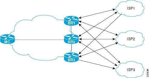
See the figure below for an example of how to implement link grouping. Three link groups, ISP1, ISP2, and ISP3 represent different Internet Service Providers (ISPs) and all three ISPs have links to interfaces on the three border routers shown in the figure below. ISP1 links are the most expensive links, but they have the best Service Level Agreement (SLA) guarantees. ISP3 links are best effort links, and these links are the cheapest links. ISP2 links are not as good as the ISP1 links, but the ISP2 links are more reliable than the ISP3 links. The cost of the ISP2 links is higher than the ISP3 links, but lower than ISP1 links. In this situation, each ISP is created as a link group and associated with an interface on each border router shown in the figure below.
Assuming four types of traffic class, video, voice, FTP, and data, each traffic class can be routed through a border router interface belonging to an appropriate link group. Video and voice traffic classes need the best links so the ISP1 link group is configured as the primary link group, with ISP2 as the fallback group. FTP traffic needs reliable links but the cost might be a factor so ISP2 is assigned as the primary group, and ISP3 is the fallback link group. Note that although ISP1 provides the most reliable links, it may be too expensive for file transfer traffic. For data traffic, ISP3 is a good choice as a primary link group, with ISP2 as the fallback group.
NoteIf you are configuring link grouping, configure the no max-range-utilization command because using a link utilization range is not compatible with using a preferred or fallback set of exit links configured for link grouping. With CSCtr33991, this requirement is removed and PfR can perform load balancing within a PfR link group.
Spillover
Performance routing link groups can be used to support spillover. Spillover is when there are two paths through the network--traffic engineering (TE) tunnels, for example--to the same provider edge (PE) router, but the tunnels take different paths across the network and the traffic is sent through one tunnel until it reaches a traffic load threshold when it spills over to the second tunnel. Using PfR link groups one tunnel is created as a primary link group and the second tunnel is the fallback link group. When the first tunnel goes out of policy, PfR switches to the fallback tunnel link group, which provides the spillover capacity until the traffic load on the first tunnel drops below the threshold. The tunnels must be established before the PfR link groups are configured.
How to Configure Performance Routing Link Groups
Implementing Performance Routing Link Groups
SUMMARY STEPSPerform this task on a master controller to set up some performance routing link groups by identifying an exit link on a border router as a member of a link group, and to create a PfR map to specify link groups for traffic classes defined in a PfR policy. In this task, a link group is set up for video traffic and a set of high bandwidth exit links are identified as members of the video link group which is identified as a primary link group. A fallback link group is also specified.
A PfR policy is created using an PfR map where the primary and fall link groups are specified for traffic classes matching the PfR map criteria. PfR probes both the primary and fallback group links and selects the best link in the primary link group for the traffic class specified in this task. If none of the primary links are within policy, PfR selects the bast link from the fallback group. For more details about link groups, see the “Performance Routing Link Grouping” section.
NoteIf you are configuring link grouping, configure the no max-range-utilization command because using a link utilization range is not compatible with using a preferred or fallback set of exit links configured for link grouping. With CSCtr33991, this requirement is removed and PfR can perform load balancing within a PfR link group.
1. enable
2. configure terminal
3. pfr master
4. border ip-address [key-chain key-chain-name]
5. interface type number external
6. link-group link-group-name [link-group-name [link-group-name]]
7. exit
8. Repeat Step 5 through Step 7 with appropriate changes to set up link groups for all the external interface.
9. interface type number internal
10. exit
11. ip access-list {standard | extended} access-list-name
12. [sequence-number] permit udp source source-wildcard [operator [port]] destination destination-wildcard [operator [port]] [dscp dscp-value]
13. Repeat Step 12 for more access list entries, as required.
14. exit
15. pfr-map map-name sequence-number
16. match traffic-class access-list access-list-name
17. set link-group link-group-name [fallback link-group-name]
18. end
19. show pfr master link-group [link-group-name]
DETAILED STEPSExample
The example output from the show pfr master link-group command displays information about performance routing link groups configured using PfR. In this example, the VIDEO link group is shown with other configured link groups.
Router# show pfr master link-group

link group video
  Border           Interface       Exit id
  192.168.1.2      Gi0/0/0         1
 link group voice
  Border           Interface       Exit id
  192.168.1.2      Gi0/0/0         1
  192.168.1.2      Gi0/0/1         2
  192.168.3.2      Gi0/0/3         4
 link group data
  Border           Interface       Exit id
  192.168.3.2      Gi0/0/2         3
Configuration Examples for Performance Routing Link Groups
Example Implementing Performance Routing Link Groups
The following example shows how to implement link groups. In this example, a PfR map named VIDEO_MAP is created to configure PfR to define a traffic class that matches an access list named ACCESS_VIDEO. The traffic class is configured to use a link group named VIDEO as the primary link group, and a fallback group named VOICE. The VIDEO link group may be a set of high bandwidth links that are preferred for video traffic.
enable
configure terminal
border 10.1.4.1
 interface GigabitEthernet 0/0/0 external
  link-group VIDEO
  exit
 interface GigabitEthernet 0/0/2 external
  link-group VOICE
  exit
 interface GigabitEthernet 0/0/1 internal
 exit
ip access-list extended ACCESS_VIDEO
 permit tcp any 10.1.1.0 0.0.0.255 eq 500
 permit tcp any 172.17.1.0 0.0.255.255 eq 500
 permit tcp any 172.17.1.0 0.0.255.255 range 700 750
 permit tcp 192.168.1.1 0.0.0.0 10.1.2.0 0.0.0.255 eq 800 any any dscp ef
 exit
pfr-map VIDEO_MAP 10
 match traffic-class access-list ACCESS_VIDEO
 set link-group VIDEO fallback VOICE
 end
Additional References
Related Documents
Related Topic
Document Title
Cisco IOS commands
Cisco IOS PfR commands: complete command syntax, command mode, command history, defaults, usage guidelines, and examples
Basic PfR configuration for Cisco IOS XE releases
“Configuring Basic Performance Routing” module
Information about configuration for the border router only functionality for Cisco IOS XE Releases 3.1 and 3.2
“Performance Routing Border Router Only Functionality” module
Concepts required to understand the Performance Routing operational phases for Cisco IOS XE releases
“Understanding Performance Routing” module
Advanced PfR configuration for Cisco IOS XE releases
“Configuring Advanced Performance Routing” module
IP SLAs overview
“Cisco IOS IP SLAs Overview” module
PfR home page with links to PfR-related content on our DocWiki collaborative environment
MIBs
Technical Assistance
Description
Link
The Cisco Support and Documentation website provides online resources to download documentation, software, and tools. Use these resources to install and configure the software and to troubleshoot and resolve technical issues with Cisco products and technologies. Access to most tools on the Cisco Support and Documentation website requires a Cisco.com user ID and password.
Feature Information for Performance Routing Link Groups
The following table provides release information about the feature or features described in this module. This table lists only the software release that introduced support for a given feature in a given software release train. Unless noted otherwise, subsequent releases of that software release train also support that feature.
Use Cisco Feature Navigator to find information about platform support and Cisco software image support. To access Cisco Feature Navigator, go to www.cisco.com/go/cfn. An account on Cisco.com is not required.
Table 1 Feature Information for Performance Routing Link Groups Feature Name
Releases
Feature Information
Performance Routing - Link Groups
Cisco IOS XE Release 3.3S
The Performance Routing - Link Groups feature introduces the ability to define a group of exit links as a preferred set of links, or a fallback set of links for PfR to use when optimizing traffic classes specified in a PfR policy.
The following commands were introduced or modified by this feature: link-group (PfR), set link-group (PfR), and show pfr master link-group.