-
Performance Routing Configuration Guide, Cisco IOS XE Release 3S
-
Configuring Basic Performance Routing
-
Performance Routing Border Router Only Functionality
-
Understanding Performance Routing
-
Configuring Advanced Performance Routing
-
BGP Inbound Optimization Using Performance Routing
-
Configuring Performance Routing Cost Policies
-
PfR Data Export v1.0 NetFlow v9 Format
-
Using Performance Routing to Control EIGRP Routes with mGRE DMVPN Hub-and-Spoke Support
-
Performance Routing Link Groups
-
Performance Routing with NAT
-
Performance Routing with NBAR CCE Application Recognition
-
Performance Routing - Protocol Independent Route Optimization (PIRO)
-
PfR RSVP Control
-
PfR Scaling Improvement for Application Traffic Class
-
PfR Simplification Phase 1
-
PfR SNMP MIB v1.0 (Read Only)
-
PfR SNMP Traps v1.0
-
Static Application Mapping Using Performance Routing
-
PfR Target Discovery v1.0
-
PfR Bandwidth Visibility Distribution for xDSL Access
-
Performance Routing Traceroute Reporting
-
PfR Voice Traffic Optimization Using Active Probes
-
 Feedback
Contents
- PfR Bandwidth Visibility Distribution for xDSL Access
- Finding Feature Information
- Restrictions for PfR Bandwidth Visibility
- Information About PfR Bandwidth Visibility
- ADSL Definition
- PfR Bandwidth Visibility Challenges
- PfR Bandwidth Visibility Resolution
- How to Configure PfR Bandwidth Visibility
- Configuring PfR Target Discovery and MC Peering for a Hub Site in Multihop Networks
- Configuring PfR Target Discovery and MC Peering for a Branch Office in Multihop Networks
- Enabling Bandwidth Resolution
- Overwriting Dynamically Discovered Receive and Transmit Bandwidth Limits
- Configuration Examples for PfR Bandwidth Visibility
- Example: Configuring PfR Bandwidth Resolution
- Additional References
- Feature Information for PfR Bandwidth Visibility
PfR Bandwidth Visibility Distribution for xDSL Access
In a network where the hub and spoke devices are connected via a multipoint tunnel, the hub site does not know about bandwidth limitations at the spoke devices. Without the updated information about bandwidth limitations, Performance Routing (PfR) cannot optimize the application traffic. Usually the spoke device connection to the Internet service provider (ISP) is a DSL connection, which can experience periodic bandwidth changes. PfR bandwidth visibility is a PfR enhancement that provides accurate maximum bandwidth information to peering PfR elements so that accurate policies can be applied automatically.
- Finding Feature Information
- Restrictions for PfR Bandwidth Visibility
- Information About PfR Bandwidth Visibility
- How to Configure PfR Bandwidth Visibility
- Configuration Examples for PfR Bandwidth Visibility
- Additional References
- Feature Information for PfR Bandwidth Visibility
Finding Feature Information
Your software release may not support all the features documented in this module. For the latest feature information and caveats, see the release notes for your platform and software release. To find information about the features documented in this module, and to see a list of the releases in which each feature is supported, see the Feature Information Table at the end of this document.
Use Cisco Feature Navigator to find information about platform support and Cisco software image support. To access Cisco Feature Navigator, go to www.cisco.com/go/cfn. An account on Cisco.com is not required.
Restrictions for PfR Bandwidth Visibility
- PfR bandwidth resolution is not supported with PfR active mode because there is no throughput data for traffic-classes.
- PfR does not support spoke-to-spoke tunneling. Disable spoke-to-spoke dynamic tunnels by configuring the ip nhrp server-only command under interface configuration mode as part of the Next Hop Resolution Protocol (NHRP) configuration.
Information About PfR Bandwidth Visibility
ADSL Definition
Digital Subscriber Line (DSL) technology is a modem technology that uses existing twisted pair telephone lines to transport high-bandwidth data, such as multimedia and video, to service subscribers. The term xDSL covers a number of similar yet competing forms of DSL, including Asymmetric DSL (ADSL/ADSL2), Symmetric DSL (SDSL), High Speed DSL (HDSL), Rate Adaptive (RADSL), and Very High Bit Data Rate DSL (VDSL) for delivering up to 52 Mbps downstream.
With Asymmetric DSL, unlike the less common Symmetric DSL, the bandwidth is greater for downloading data than for uploading data.
At the customer end of the connection, a DSL modem converts data from the digital signals used by computers into a voltage signal of a suitable frequency range, which is then applied to the phone line. At the exchange end, a Digital Subscriber Line Access Multiplexer (DSLAM) terminates the DSL circuits and aggregates them, where they are handed off to other networking transports. In the case of ADSL, the voice component is also separated at this step, either by a filter integrated in the DSLAM or by specialized filtering equipment installed before it.
PfR Bandwidth Visibility Challenges
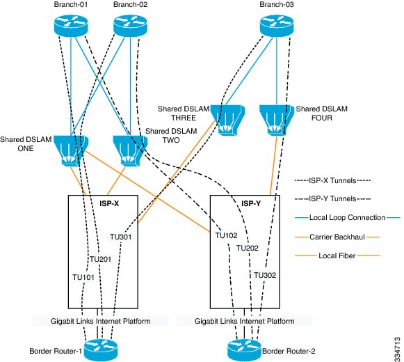
In a network where the hub and spoke devices are connected via a multi-point tunnel, the hub site does not know about bandwidth limitations at the spoke devices. Without the updated information about bandwidth limitations, Performance Routing (PfR) cannot optimize the application traffic. Usually the spoke device connection to the Internet Service Provider (ISP) is a DSL connection, which can experience periodic bandwidth changes. For an example of such a network, see the network diagram below.
PfR can redirect application traffic from one DMVPN/MGRE tunnel to another if the hub-spoke link utilization crosses a configured threshold, but PfR has no visibility into how congested a particular spoke is. There is a need for a mechanism that can discover updated receive (Rx) and transmit (Tx) limits at the spoke side and propagate the limit information to the hub, where the limit information can be used by PfR to effectively manage the application traffic.
Scenarios Creating ADSL Bandwidth Visibility Challenges
There are three main ADSL scenarios which can cause PfR bandwidth visibility challenges:
- ADSL retrain—Automatic or manual intervention can force the DSLAM into line reconditioning and retraining in which the bandwidth allocation for the line changes. The interventions can occur without notice. For an upwards retrain, the impact on the branch is minimal. For a downwards retrain, the branch can lose bandwidth, a common issue in congested exchanges. The ability to monitor and assess when to move the traffic through another tunnel is key to maintaining a smooth retraining.
- ADSL congestion—During congested periods, traffic can be held up. Under these circumstances it is imperative that the branch traffic be allowed to take the best possible path—and be distributed as well as possible over all links.
- ADSL intermittent faults—There are occasions (sometimes quite frequent) when there are intermittent faults that cause minor outages. The investigation of these issues normally takes several working days (no SLA). Significant numbers of these intermittent faults manifest themselves as drops at the higher usage of the “allocated” bandwidth. The ability must exist to effectively change the usage profile of any single tunnel to rebalance the traffic loadings until the ISP has repaired the issue.
PfR Bandwidth Visibility Resolution
Bandwidth visibility is a Performance Routing (PfR) enhancement that provides accurate maximum bandwidth information to peering PfR elements so that accurate policies can be applied automatically. In a network where bandwidth visibility is an issue, there are typically hub and spoke devices connected via a multi-point tunnel, and the hub site does not know about bandwidth limitations at the spoke devices. Without the updated information about bandwidth limitations, PfR cannot optimize the application traffic. Currently the bandwidth limitations are updated manually, but this is not a scalable solution.
PfR bandwidth visibility leverages the existing PfR target discovery feature. The existing SAF-based peering infrastructure can be used to propagate the bandwidth information, as well as target information, from a spoke device to the hub device. On the hub, the PfR master controller builds a database of peers and tracks their maximum receive and transmit bandwidth information. The border routers track the total amount of bandwidth transmitted to a given peer network and report it back to the master controller. If the total amount of bandwidth transmitted to a given peer at any time exceeds certain percentage of the receiving capacity of that peer, PfR can reroute that application traffic to an alternate link, avoiding congestion at the spoke device.
NotePfR does not support spoke-to-spoke tunneling. Disable spoke-to-spoke dynamic tunnels by configuring the ip nhrp server-only command under interface configuration mode as part of the Next Hop Resolution Protocol (NHRP) configuration.
To enable PfR bandwidth resolution, PfR target discovery must be configured on all devices on which PfR bandwidth-resolution is to be enabled. PfR bandwidth resolution is then enabled on all master controller devices. Both dynamic and static target discovery is supported by PfR bandwidth resolution. After bandwidth resolution is enabled, receive and transmit bandwidth limits are dynamically discovered and propagated using PfR target discovery. A mechanism is available to allow an overwrite of the dynamically discovered limits.
NotePfR bandwidth resolution is not supported with PfR active mode because there is no throughput data for traffic-classes.
How to Configure PfR Bandwidth Visibility
Configuring PfR Target Discovery and MC Peering for a Hub Site in Multihop Networks
SUMMARY STEPSPerform this task to configure PfR master controller (MC) peering at the master controller at the headend of the network, usually a hub site master controller. The master controller must be a device with routing capability. This task assumes a multihop type of network where the network cloud between the hub site and the branch sites is not under the control of the customer or is not SAF-enabled. In this design, the hub site MC will be a Service Advertisement Facility (SAF) forwarder hub with which the branch MC SAF forwarders peer to exchange advertisements. The hub site MC will accept peering requests from branch MCs with the same SAF domain ID and MD5 authentication.
NoteIn this task, dynamic PfR target discovery is enabled. This method is desirable when SAF is already enabled in the network for other applications or there is existing neighbor adjacency between MCs and SAF. For example, in a DMVPN WAN, if the PfR MCs coexist on the DMVPN tunnel devices, they also have SAF adjacency and do not require static peering.
NotePfR does not support spoke-to-spoke tunneling. Disable spoke-to-spoke dynamic tunnels by configuring the ip nhrp server-only command under interface configuration mode as part of the Next Hop Resolution Protocol (NHRP) configuration.
1. enable
2. configure terminal
3. pfr master
4. target-discovery
5. mc-peer [head-end | peer-address] [loopback interface-number] [description text] [domain domain-id]
6. end
DETAILED STEPSConfiguring PfR Target Discovery and MC Peering for a Branch Office in Multihop Networks
Perform this task to configure PfR MC peering using static mode for PfR target discovery at a branch office that is acting as a spoke router. In this example, the IP address of the PfR master controller hub device at a head office (headend) of the network is configured as a loopback interface to allow MC peering. This task assumes a multihop type of network where the network cloud between the hub site and the branch offices is not under the control of the customer.
NotePfR does not support spoke-to-spoke tunneling. Disable spoke-to-spoke dynamic tunnels by configuring the ip nhrp server-only command under interface configuration mode as part of the Next Hop Resolution Protocol (NHRP) configuration.
Before You BeginSUMMARY STEPSPfR master controller (MC) peering must be configured on a device with routing capability located at the hub site (headend) of the network.
1. enable
2. configure terminal
3. pfr master
4. mc-peer [peer-address loopback interface-number] [description text] [domain domain-id]
5. target-discovery
6. end
DETAILED STEPSEnabling Bandwidth Resolution
This task is performed on all PfR master controllers in every hub and spoke in the participating site.
Before You BeginSUMMARY STEPS
NotePfR target discovery must be configured before enabling bandwidth resolution. Both dynamic and static target discovery is supported by PfR bandwidth resolution. PfR bandwidth resolution is not supported with PfR active mode because there is no throughput data for traffic-classes.
NotePfR does not support spoke-to-spoke tunneling. Disable spoke-to-spoke dynamic tunnels by configuring the ip nhrp server-only command under interface configuration mode as part of the Next Hop Resolution Protocol (NHRP) configuration.
1. enable
2. configure terminal
3. pfr master
4. bandwidth-resolution
DETAILED STEPSOverwriting Dynamically Discovered Receive and Transmit Bandwidth Limits
SUMMARY STEPSPerform this task at a PfR master controller to manually specify the maximum receive (Rx) and transmit (Tx) limits for a PfR external interface. When bandwidth-resolution is enabled, receive and transmit bandwidth limits are dynamically discovered and propagated using PfR target discovery. Use this task to overwrite the dynamically discovered limits using PfR bandwidth resolution.
After an external interface has been configured for a border router, PfR automatically monitors the utilization of external links on a border router every 20 seconds. The utilization is reported back to the master controller and, if the utilization exceeds the specified limit, PfR selects another exit link for traffic classes on that link. Only absolute values, in kilobits per second (kbps), can be specified to overwrite the dynamically discovered bandwidth limits.
1. enable
2. configure terminal
3. pfr master
4. border ip-address [key-chain key-chain-name]
5. interface type number external
6. maximum utilization receive absolute kbps
7. max-xmit-utilization absolute kbps
8. end
DETAILED STEPSConfiguration Examples for PfR Bandwidth Visibility
Example: Configuring PfR Bandwidth Resolution
NotePfR target discovery must be configured before bandwidth resolution is enabled. Both dynamic and static target discovery is supported by PfR bandwidth resolution.
The following configuration can be used in multihop networks where the network cloud between the head office and branch offices or remote sites is not controlled by the customer or is not SAF-enabled. Configuration examples are shown for three master controllers, one at the head office and two at branch offices. PfR bandwidth resolution is enabled on all PfR master controller (MC) devices. Output for the show pfr master bandwidth-resolution command is shown for all three sites.
NoteIn the following examples, the hub and spoke device hostnames were configured as “Router-hub,” “Router-spoke1,” or “Router-spoke2,” but the device can be any device with routing capability that supports PfR.
Hub MC Bandwidth Resolution Configuration
The hub device has routing capability and is in the head office. In this example, PfR bandwidth resolution is enabled on the master controller.
Router-hub> enable
Router-hub# configure terminal
Enter configuration commands, one per line.  End with CNTL/Z.
Router-hub(config)# pfr master
Router-hub(config-pfr-mc)# bandwidth-resolution
Router-hub(config-pfr-mc)# end
Spoke1 MC Bandwidth Resolution Configuration
The spoke1 device has routing capability and is in a branch (spoke) office. In this example, PfR bandwidth resolution is enabled on the master controller at the branch office.
Router-spoke1> enable
Router-spoke1# configure terminal
Enter configuration commands, one per line.  End with CNTL/Z.
Router-spoke1(config)# pfr master
Router-spoke1(config-pfr-mc)# bandwidth-resolution
Router-spoke1(config-pfr-mc)# end
Spoke2 MC Bandwidth Resolution Configuration
The spoke2 device has routing capability and is in a second branch (spoke) office. In this example, PfR bandwidth resolution is enabled on the master controller at the second branch office.
Router-spoke2> enable
Router-spoke2# configure terminal
Enter configuration commands, one per line.  End with CNTL/Z.
Router-spoke2(config)# pfr master
Router-spoke2(config-pfr-mc)# bandwidth-resolution
Router-spoke2(config-pfr-mc)# end
Example Output for PfR Bandwidth Resolution
The following output is from the master controller for the hub device after PfR bandwidth resolution is enabled:
Router-hub# show pfr master bandwidth-resolution all

Border Router: 10.20.20.2           External Interface: Tu10
MC-peer address  Overlay address   Rx BW [kbps]   Tx BW [kbps]  Tx Load [kbps]
172.17.51.1      10.110.110.2      1000           900           0
172.20.61.1      10.110.110.3      1000           900           35

Border Router: 10.20.20.3           External Interface: Tu20
MC-peer address  Overlay address   Rx BW [kbps]   Tx BW [kbps]  Tx Load [kbps]
172.17.51.1      10.90.90.2        1000           900           18
172.20.61.1      10.90.90.3        803            903
The following output is from the master controller for the hub device after PfR bandwidth resolution is enabled and displays the output for the master controller peer at IP address 172.20.61.1:
Router-hub# show pfr master bandwidth-resolution 172.20.61.1

PfR Bandwidth Resolution Database
MC-peer: 172.20.61.1
Border Router  External Interface  Overlay Address  Rx BW [kbps] Tx BW [kbps] Tx Load [kbps]
10.20.20.2     Tu10                10.110.110.3     1000         900          35
10.20.20.3     Tu20                10.90.90.3       803          903          0
Additional References
Related Documents
Related Topic
Document Title
Cisco IOS commands
Cisco IOS PfR commands: complete command syntax, command mode, command history, defaults, usage guidelines, and examples
Basic PfR configuration for Cisco IOS XE releases
“Configuring Basic Performance Routing” module
Information about configuration for the border router only functionality for Cisco IOS XE Releases 3.1 and 3.2
“Performance Routing Border Router Only Functionality” module
Concepts required to understand the Performance Routing operational phases for Cisco IOS XE releases
“Understanding Performance Routing” module
Advanced PfR configuration for Cisco IOS XE releases
“Configuring Advanced Performance Routing” module
IP SLAs overview
“Cisco IOS IP SLAs Overview” module
PfR home page with links to PfR-related content on our DocWiki collaborative environment
MIBs
Technical Assistance
Description
Link
The Cisco Support and Documentation website provides online resources to download documentation, software, and tools. Use these resources to install and configure the software and to troubleshoot and resolve technical issues with Cisco products and technologies. Access to most tools on the Cisco Support and Documentation website requires a Cisco.com user ID and password.
Feature Information for PfR Bandwidth Visibility
The following table provides release information about the feature or features described in this module. This table lists only the software release that introduced support for a given feature in a given software release train. Unless noted otherwise, subsequent releases of that software release train also support that feature.
Use Cisco Feature Navigator to find information about platform support and Cisco software image support. To access Cisco Feature Navigator, go to www.cisco.com/go/cfn. An account on Cisco.com is not required.
Table 1 Feature Information for PfR Bandwidth Visibility Feature Name
Releases
Feature Information
PfR Bandwidth Visibility Distribution for xDSL Access
15.3(1)T
Cisco IOS XE Release 3.8S
PfR bandwidth visibility is a PfR enhancement that provides accurate maximum bandwidth information to peering PfR elements so that policies can be applied automatically.
The following commands were introduced or modified: bandwidth-resolution, debug pfr border bandwidth-resolution, debug pfr master bandwidth-resolution, show pfr master bandwidth-resolution.