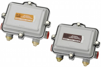
The Cisco® Multimedia Line Equalizer/Reverse Conditioner (LEQ/RC), shown in Figure 1, improves network performance on both the forward and reverse paths in a coaxial transmission system.
In the forward path, the fixed forward equalizer offsets undesirable down-tilt associated with cumulative cable and passive losses, allowing tap port RF levels to be maintained within desired design limits, even at taps located near the ends of lines.
In the reverse path, plug-in attenuation allows RF levels to be conditioned for optimal performance of critical reverse path services. By selectively adding reverse attenuation at Cisco Multimedia LEQ/RC locations, the range of RF levels transmitted from closed-loop customer premises equipment in a given service area can be narrowed considerably.
With greater percentages of devices, such as high-speed data and telephony modems, transmitting in the upper end of their RF transmit ranges, improvements in carrier-to-ingress and carrier-to-noise performance can be realized.
Figure 1. Cisco Multimedia Line Equalizer/Reverse Conditioner
Features
• Fixed 9 dB or 11 dB forward equalizers
• Plug-in attenuator location for reverse-path optimization
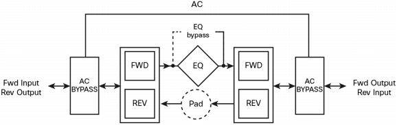
• Connection beam non-interruptible AC and RF bypass (Figure 2) that optimizes network availability during maintenance periods
• Equalizer in and out bypass, which allows reverse conditioning deployment network locations where forward equalization is not desired
• 15A current passing capability, which allows placement in all portions of the network
• 6 kV surge protection
• Circuit contained in faceplate, compatible with existing Cisco line equalizer products
• Rugged, polymer-coated housing that provides reliable performance in the most challenging environments; additional labels provided in packaging mark the tap containing a DC/EQ module
Figure 2. Block Diagram
Product Specifications
Tables 1 through 7 provide product specifications.
Table 1. Insertion Loss
Insertion Loss
Frequency
Bypass Mode
Equalization Mode
9 dB
11 dB
Typical
Maximum
Typical
Maximum
Typical
Maximum
5 MHz
-0.5 dB
-1.0 dB
-0.5 dB
-1.0 dB
-0.5 dB
-1.0 dB
10 MHz
-0.4 dB
-1.0 dB
-0.4 dB
-1.0 dB
-0.4 dB
-1.0 dB
40 MHz
-0.7 dB
-1.0 dB
-0.7 dB
-1.0 dB
-0.7 dB
-1.0 dB
50 MHz
-0.9 dB
-1.0 dB
-0.9 dB
-1.0 dB
-0.9 dB
-1.0 dB
65 MHz
-1.0 dB
-1.3 dB
-1.0 dB
-1.3 dB
-1.0 dB
-1.3 dB
86 MHz
-1.1 dB
-1.3 dB
-8.9 dB
-9.6 dB
-10.8 dB
-11.6 dB
450 MHz
-0.9 dB
-1.3 dB
-5.5 dB
-5.8 dB
-5.9 dB
-6.7 dB
550 MHz
-1.0 dB
-1.4 dB
-4.5 dB
-5.1 dB
-4.8 dB
-5.8 dB
650 MHz
-1.0 dB
-1.7 dB
-3.7 dB
-4.5 dB
-4.0 dB
-5.0 dB
750 MHz
-1.1 dB
-1.8 dB
-3.1 dB
-3.9 dB
-3.3 dB
-4.3 dB
870 MHz
-1.4 dB
-2.0 dB
-2.3 dB
-3.2 dB
-2.7 dB
-3.5 dB
1000 MHz
-1.9 dB
-2.2 dB
-2.2 dB
-2.7 dB
-2.3 dB
-2.7 dB
Table 2. Return Loss
Return Loss
Frequency
Bypass Mode
Equalization Mode
9 dB
11 dB
Typical
Minimum
Typical
Minimum
Typical
Minimum
5 to 10 MHz
-16 dB
-15.5 dB
16 dB
-15.5 dB
-16 dB
-15.5 dB
11 to 65 MHz
-18 dB
-16 dB
17 dB
-16 dB
-17 dB
-16 dB
86 to1000 MHz
-18 dB
-16 dB
17 dB
-16 dB
-17 dB
-16 dB
Table 3. Flatness
Flatness
Frequency
Bypass Mode
Equalization Mode
9 dB
11 dB
Typical
Maximum
Typical
Maximum
Typical
Maximum
5 to 65 MHz
0.65 dB
0.65 dB
0.65 dB
0.65 dB
0.65 dB
0.65 dB
86 to 1000 MHz
0.75 dB
0.75 dB
0.75 dB
0.75 dB
0.75 dB
0.75 dB
Table 4. Group Delay
Group Delay
Frequency
Typical
Maximum
Forward
91.25 to 94.83 MHz
15 ns
20 ns
97.25 to 100.83 MHz
7 ns
10 ns
Reverse
5.0 to 6.5 MHz
40 ns
40 ns
6.5 to 8.0 MHz
20 ns
30 ns
8.0 to 9.5 MHz
9 ns
15 ns
60.5 to 62.0 MHz
9 ns
15 ns
62.0 to 63.5 MHz
8 ns
20 ns
63.5 to 65 MHz
17 ns
30 ns
Table 5. Power Passing
Power Passing
Frequency
Bypass Mode
Equalization Mode
9 dB
11 dB
-
15A
15A
15A
Table 6. Hum Modulation
Hum Modulation
Frequency
Bypass Mode
Equalization Mode
9 dB
11 dB
5 to 10 MHz
-60 dBc @12A
-60 dBc @12A
-60 dBc @12A
11 to 1000 MHz
-60 dBc @12A
-60 dBc @12A
-60 dBc @12A
Table 7. Safety and Compliance
Safety and Compliance
Items
Specs
EMC
FCC Part 76, Subpart K, FCC Part 15, Subpart B, Class B
1. Chrominance and luminance at 3.58 MHz above the video carrier
2. Propagation delay in 2 MHz bandwidth
3. Unless otherwise noted, all the specifications in Table 1 through Table 7 reflect typical station performance at stated reference levels in the recommended operating configurations. Specifications are based on measurements made in accordance with SCTE/ANSI standards (where applicable), using standard frequency assignments.
Ordering Information
To place an order, visit the Cisco Ordering Home Page and refer to Table 8 and Table 9, which list the part numbers for the Cisco Multimedia LEQ/RC.
Table 8. Ordering Information
Description
Part Number
Cisco Multimedia LEQ/RC, 65/86 MHz split, 9 dB Forward EQ
4042859
Cisco Multimedia LEQ/RC, 65/86 MHz split, 11 dB Forward EQ
4042860
Table 9. Plug-In Attenuators
Value
Part Number
Value
Part Number
Value
Part Number
0 dB
574475
6 dB
574481
12 dB
574487
1 dB
574476
7 dB
574482
13 dB
574488
2 dB
574477
8 dB
574483
14 dB
574489
3 dB
574478
9 dB
574484
15 dB
574490
4 dB
574479
10 dB
574485
75 ohm
574496
5 dB
574480
11 dB
574486
For More Information
Cisco Multimedia Line Equalizer/Reverse Conditioner products include some of the industry's most complete range of high-performance components. For additional information, please go to: http://www.cisco.com/en/US/products/ps9101/index.html.