The Cisco® Compact Electronic Gain Control (EGC) Amplifier Model 93250-93251 combines powerful performance with ease of use to meet operators' growing demands for advanced products. It provides advanced features to help reduce operating costs by streamlining amplifier deployment and configuration, and it is especially well suited for network upgrades because it provides increased reverse gain.
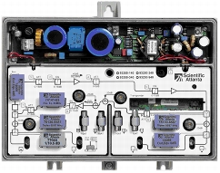
Figure 1. Cisco Compact EGC Amplifier Model 93250-93251
The amplifier (Figure 1) performs to 1 GHz in the forward path, and it can be configured electronically, using a handheld programmer terminal, for rapid initial setup or for adjustments that are needed as network requirements shift. All settings can be done without interrupting service, an especially important capability in networks that deliver voice over IP (VoIP) services. Settings for this EGC amplifier can be established or modified using a handheld programmer terminal. To streamline configuration, settings from one amplifier can be uploaded to the handheld programmer terminal for downloading to other amplifiers. Different forward-gain settings can be obtained in the amplifier, allowing it to support several different applications within the network, so a single amplifier model can help reduce inventory and costs.
The number of amplifier plug-ins is reduced to a minimum to help operators keep inventory and costs down. The full-range electronic attenuators and equalizers offer improved versatility and make it possible to achieve the same adjustment range as with conventional plug-in or potentiometer solutions. Plug-in diplex filters are used to determine the forward and reverse band split.
To meet future demands for more bandwidth, the amplifier offers an electronic 862 MHz to 1 GHz field-programmable bandwidth extension, as well as a reverse path that can be upgraded to 200 MHz.
The Cisco Compact EGC Amplifier Model 93250-93251 can be configured with a Cisco status-monitoring transponder (meeting EuroDOCSIS and DOCSIS standards) to provide remote monitoring of critical amplifier parameters and remote control of the built-in three-state reverse switch. All amplifier settings are remotely addressable using a web GUI or Simple Network Management Protocol (SNMP) to help reduce truck rolls and associated costs.
Features
• Gallium arsenide field-effect transistor (GaAsFET) gain block technology for improved distortion and noise performance
• 8A power passing
• Improved output level and flatness
• 6 kV surge protection
• Plug-in, self-contained diplex filters for easy upgrade of reverse path bandwidth
• Easy plug-in mounting of transponder (no change of lid nor use of test points for cable connection)
• Optional status monitoring and control
• Integrated three-state reverse switch (on/-6 dB/off) allows the reverse input to be isolated for noise and ingress troubleshooting
• Compact EuroDOCSIS/DOCSIS transponder supported
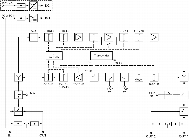
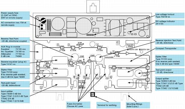
Figure 2. Block Diagram and Overview
Block Diagram
Overview
Specifications
Table 1 provides product specifications for the Cisco Compact EGC Amplifier Model 93250-93251.
Table 1. Product Specifications
Forward
Units
Description
Notes
Frequency range
MHz
47 to 862
47 to 1000
1
Gain
dB
Selectable 28, 34, 40
Flatness
dB
± 0.50
± 0.75
2
Input attenuator
dB
0 to 18 in 0.5 dB step
Input equalizer
dB
0 to 18 in 0.5 dB step
Interstage attenuator
dB
0 to 6 in 0.5 dB step
Interstage pre-equalizer
dB
0 to 15 in 0.5 dB step
Input test point
dB
-20 ± 1.5
Output test point
dB
-20 ± 0.50
-20 ± 0.75
Number of outputs
-
1 or 2
3
Return loss
• Input, output port
• Input, output test point
dB
> 18
> 20
2, 4
Noise figure
dB
7.0
5
Signal feed through loss
dB
£ 1.0
Output Level @ 42 ch CENELEC
• Composite triple beat (CTB) ≥60 dB
• Composite second order (CSO) ≥60 dB
dBµV
114
114
6, 7
Reverse
Units
Description
Notes
Frequency range
MHz
5 to 65
5 to 200
1
Gain
dB
Selectable 20, 25
Flatness
dB
± 0.5
± 0.75
Input attenuators
dB
0 to 20 in 0.5 dB step
Output attenuators
dB
0 to 18 in 0.5 dB step
Output equalizer
dB
0 to 15 in 0.5 dB step
Test point
dB
-20 ± 0.5
Signal injection point
dB
-20 ± 0.5
Return loss at test point
dB
> 20 @ 5 to 10 MHz
> 23 @ 10 to 200 MHz
4
Return loss at input and output
dB
> 18
4, 8
Output level
• IMD3 ≥ 60 dB
• IMD2 ≥ 60 dB
dBμV
117
112
111
107
Three-state reverse switch, EM controlled
-
On/-6 dB/off
Noise figure
dB
£ 7.5
£ 8.0
* Unless otherwise noted, all data given are for the amplifier with standard configuration for 1 output.
General Performance
Units
Description
Notes
Transponder receive level attenuation
dB
-33 ± 0.75
Transponder transmit insertion loss
dB
-20 ± 0.75
Surge protection
kV, µs
6, 1.2/50
9
Enclosure category
-
IP 66
Emission, EN 50083-2
dBpW
< 20
Screening
dB
> 85
Connectors, inputs, and outputs (reduction)
-
PG 11 (5/8 in.)
Test point
-
F-connector, female
Electrical
65V coaxial line powering (rms, sine)
VAC
24 to 65
230V mains line powering (rms, sine)
VAC
187 to 250
Power consumption, network powered
W
25.5 with built-in reverse amp
27.5 with plug-in transponder
Current draw
A AC
See table
10
Maximum current, inputs and outputs
A AC
8
Maximum current, local input
A AC
15
Hum modulation
dB
£ -65
Compliance and Safety
Electrical safety
-
EN 50083-1
EN 60065
IEC 65
EMC emissions
-
EN 50083-2
Environmental
Operating temperature range
°C
°F
-20 to 55
-4 to 131
Mechanical
Housing dimensions model 93250
(W x H x D)
mm
in.
230 x 190 x 120
9.1 x 7.5 x 4.7
Housing dimensions model 93251
(W x H x D)
mm
in.
230 x 155 x 95
9.1 x 6.1 x 3.7
Packaging dimensions model 93250
(W x H x D)
mm
in.
270 x 285 x 130
10.6 x 11.2 x 5.1
Packaging dimensions model 93251
(W x H x D)
mm
in.
270 x 285 x 100
10.6 x 11.2 x 3.8
Weight model 93250
kg
lb
3.0
6.6
Weight model 93251
kg
lb
2.7
6.0
Notes:
1. Frequency range depends on plug-in diplex filters and amplifier settings
2. With diplex filters
3. Two outputs that can be activated by using splitter or directional coupler
4. At 40 MHz red, 1.5 dB/octave
5. Maximum gain, no equalization
6. With 6 dB interstage EQ
7. Change in CTB, CSO, and noise figure with different interstage attenuation, relative to 0 dB
40 dB
CTB
CSO
Noise Figure
2 dB
1
2
0.1
4 dB
2
2
0.2
6 dB
2
2
0.3
34 dB
CTB
CSO
Noise Figure
2 dB
2
1
0.1
4 dB
3
1
0.2
6 dB
4
1
0.3
28 dB
CTB
CSO
Noise Figure
2 dB
1
1
0.2
4 dB
3
1
0.6
6 dB
4
1
1.0
8. Start from 7 MHz
9. According to IEC60 on input and output with diplex filters
10. AC current draw is tested with 50-meter coaxial cable
AC Input Voltage (V)
24
30
35
40
45
50
55
60
65
AC Current Draw (A)
Without transponder
1.24
1.00
0.87
0.78
0.71
0.65
0.60
0.57
0.54
With transponder
1.29
1.04
0.90
0.79
0.73
0.66
0.62
0.58
0.56
Ordering Information
To place an order, visit the Cisco Ordering Home Page, and use the information provided in Table 2.
Table 2. Ordering Information for the Cisco Compact EGC Amplifier Model 93250-93251
Unconfigured Amplifier
Part Number
Cisco Compact EGC Amplifier, 862MHz/1GHz, 28/40dB, 230V Electronic adjustable Att & Eq, PG11 at input/output, Plug-in Xpdr
A93250.10240
Cisco Compact EGC Amplifier, 862MHz/1GHz, 28/40dB, 230V Electronic adjustable Att & Eq, PG11 at input/output, Plug-in Xpdr
A93250.10340
Cisco Compact EGC Amplifier, 862MHz/1GHz, 28/40dB, 230V, Electronic adjustable Att & Eq, PG11 at input/output, Plug-in Xpdr
A93251.10240
Cisco Compact EGC Amplifier, 862MHz/1GHz, 28/40dB, 65V, Electronic adjustable Att & Eq, PG11 at input/output, Plug-in Xpdr
A93251.10340
Preconfigured Amplifier
Part Number
Cisco Compact EGC Amplifier, 862MHz/1GHz, 28/40dB, 230V; Elec adj Att & Eq, PG11 at in/out, Plug-in Xpdr; Configured for 65MHz rev;0dB IN;0dB OUT;0dB AUX
A93250.1024065
Cisco Compact EGC Amplifier, 862MHz/1GHz, 28/40dB, 65V; Elec adj Att & Eq, PG11 at in/out, Plug-in Xpdr; Configured for 65MHz rev;0dB IN;0dB OUT;0dB AUX
A93250.1034065
Cisco Compact EGC Amplifier, 862MHz/1GHz, 28/40dB, 230V; Elec adj Att & Eq, PG11 at in/out, Plug-in Xpdr; Configured for 65MHz rev;0dB IN;0dB OUT;0dB AUX
A93251.1024065
Cisco Compact EGC Amplifier, 862MHz/1GHz, 28/40dB, 65V, Elec adj Att & Eq, PG11 at in/out, Plug-in Xpdr; Configured for 65MHz rev;0dB IN;0dB OUT;0dB AUX
A93251.1034065
The following required accessories must be ordered separately.
Required Accessories
Part Number
Plug-in Diplex Filter: 2 required, choose from the following options:
• 30/47 MHz split
• 42/54 MHz split
• 65/87 MHz split
• 85/105 MHz split
A75130.103047
A75130.104254
A75130.106587
A75130.1085105
Plug-in Reverse Equalizer: 1 required, choose from the following options:
• 30 MHz reverse band
• 42 MHz reverse band
• 65 MHz reverse band
• 85 MHz reverse band
A74141.1030
A74141.1042
A74141.1065
A74141.1085
Plug-in at input: 1 required, choose from the following options:
• 1 link 0 dB at input
• 1 splitter 3.5/3.5 dB at input
• 1 splitter 2/6 at input
• 1 splitter 1/10.5 dB at input
• 1 splitter 0.6/14 dB at input
A74089.10
A77041.10
A77042.10
A77043.10
A77044.10
Plug-in at AUX: 1 required, choose from the following options:
• 1 link 0 dB
• 1 attenuator 2, 4, 6, 8, 10 or 12 dB (xx=02, 04, 06, 08, 10 or 12)
• 1 equalizer/862 MHz Tilt 3, 6, 9, 12, 15 dB
• 1 inverse equalizer 862 MHz -3, -6, -9 or -12 dB (xx=03, 06, 09 or 12)
A74069.10
A77150.100xx
A74100.10xxx
A74190.10xx
Plug-in at output: 1 required, choose from the following options: