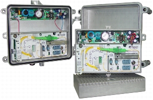
The Cisco Compact EGC Fiber Deep Node (FDN) is a small node designed to meet the growing need for network segmentation (Figure 1). It provides advanced features and benefits at an attractive price point and helps operators reduce operating costs by streamlining node segmentation deployments and configuration. It is also well suited for migration toward fiber to the cabinet (FTTC) and fiber to the building (FTTB) architectures.
The node can operate at an output level of 117 dBμV in the forward path and can be configured electronically for quick initial setup or adjustments that are needed as network requirements shift. All settings can be done without interrupting service, an especially important capability in networks that deliver interactive services such as voice over IP (VoIP) and high-speed data. The node is equipped with an interface that allows configuration through a handheld programmer terminal or by connecting to a standard PC. This interface allows the settings to be stored and reapplied to maintain a streamlined configuration.
The node's large optical input range and high RF output level provide flexible options for use with a large variety of reverse transmitters and to support a variety of applications within the network.
The number of plug-ins has been minimized to help operators keep inventory and costs down. The full-range electronic attenuators and equalizers offer improved versatility and make it possible to achieve the same adjustment range as with conventional plug-ins or potentiometer solutions. A plug-in diplexer filter is used to determine the forward and reverse band split.
To meet future demands for more bandwidth, the node offers an electronic 862 MHz to 1 GHz field-programmable bandwidth extension, and the reverse path can be upgraded to 200 MHz.
The Cisco Compact EGC FDN Model A90100 and A90300 can be configured with a Cisco status monitoring transponder (meeting EuroDOCSIS and DOCSIS standards) to allow remote monitoring of critical node parameters and remote control of the built-in three-state reverse switch. All node settings are remotely addressable using a web GUI and Simple Network Management Protocol (SNMP) to help reduce truck rolls and associated cost.
Figure 1. Cisco Compact EGC Fiber Deep Nodes A90100 and A90300
Features
• Gallium arsenide field-effect transistor (GaAsFET) gain block technology for improved distortion and noise performance
• High-output level up to 117 dBµV with improved composite triple beat (CTB) and composite second order (CSO) values
• Built-in output splitter (plug-in)
• Extensive range of plug-in reverse transmitter options, including Fabry-Perot (FP), distributed feedback (DFB), and coarse wavelength-division multiplexing (CWDM)
• Two different housings: compact indoor housing (IP54) and hardened outdoor housing (IP68)
• Integrated three-state reverse switch (on/-6 dB/off) that allows the reverse input to be isolated for noise and ingress troubleshooting
• Optional ingress block filter (plug-in)
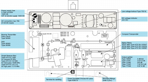
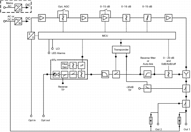
Figure 2. Overview and Block Diagram
Overview
Block Diagram
Product Specifications
Tables 1 through 3 provide product specifications for the Cisco Compact EGC Fiber Deep Nodes A90100 and A90300.
Table 1. Optical and RF Specifications
Specification
Value
Notes
Optical wavelength
1100 to 1600 nm
Optical input level (maximum)
6 dBm
Optical range
-7 to 2 dBm
Automated gain control (AGC) range
-7 to 2 dBm
2
AGC accuracy
±1 dB
Input noise current, maximum
≤ 7.0 pA/ÖHz (below 862 MHz)
≤ 8.0 pA/ÖHz (862 to 1002 MHz)
Frequency range
45 to 1002 MHz
6
Number of outputs
2
3
Output level
95 to 117 dBµV (35 to 57dBmV)
1
Level flatness
±0.75 dB @ 45 to 862 MHz
±1 dB @ 45 to 1GHz
Output level temperature variation
±1 dB
Intermodulation
• CTB
• CSO
≥ 58 dBc
≥ 58 dBc
4
Interstage equalizer
0 to 15 dB
Output return loss
≥ 20 dB
5
Test point, outputs
-20±0.5 dB @ 45 to 862 MHz
-20±0.75 dB @ 45 to 1002 MHz
Frequency range
5 to 200 MHz
6
Insertion loss
4±0.5 dB @ 5 to 65 MHz
≤ 6 dB @ 65 to 200 MHz
7
Input return loss
≥ 20 dB
8
Test point, outputs
Connected to Rev. Tx Transmitter
9
Isolation, reverse switch in off position
> 55 dB @ 5 to 65 MHz
> 45 dB @ 65 to 200 MHz
Three-state reverse switch (ingress)
On/-6 dB/off
Table 2. General Specifications
Specification
Value
Notes
Hum modulation
≤ -65 dB
Transient protection
6 kV, 1, 2 µs/50 µs
Screening effectiveness
≥ 85 dB
Power Supply
Supply voltage
Mains powered
Network powered
187 to 250 VAC, 50 to 60 Hz
24 to 65 VAC
Power consumption
General without plug-ins
Compact transponder
FP reverse Tx
DFB reverse Tx
≤ 30W
≤ 2.0W
≤ 2.5W
≤ 3.0W
10
Maximum current, outputs
7 A AC
Maximum current, external supply
15 A AC
11
Safety and Compliance
Electrical safety
EN 50083-1, EN 60065, IEC 65
EMC emissions
EN 50083-2
Connectors
RF outputs
PG11
RF test points
F-connector
Optical adapter
• Standard
• Optional
SC/APC to SC/APC
SC/APC to E2000
12
LCI interface
Mini jack, female
Mechanics
A90100, Indoor Use
A90300, Outdoor Use
Housing
Die-cast, aluminum
Water and dust ingress rating
IP54
IP68
Operating temperature
-15 to 55°C
5 to 131°F
-25 to 60°C
-13 to 140°F
Dimensions: W x H x D
230 x 188 x 119 mm
9.1 x 7.4 x 4.7 in.
297 x 145 x 215 mm
11.7 x 5.7 x 8.5 in.
Weight
3.2 kg
7.0 lb
4.7 kg
10.4 lb
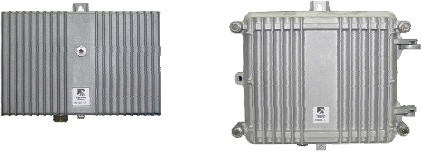
Housing: Ports are at the base of the housing for easy connection to underground cabling. (Left: A90100, right: A90300)
Notes:
1. Output level @ 1310 nm (m = 3.25%) or 1550 nm (m = 3%); valid for the node being configured with one RF output port.
2. Reducing output level will extend the AGC range as shown below.
Output Level
AGC Range dBm
@ 1310 nm (m = 3.25%) or 1550 nm (m = 3%)
Output Level
AGC Range dBm
@ 1310 nm (m = 3.25%) or 1550 nm (m = 3%)
117
-7 to 2
111
-10 to 2
116
-7.5 to 2
110
-10.5 to 2
115
-8 to 2
109
-11 to 2
Output Level
AGC Range dBm
@ 1310 nm (m = 3.25%) or 1550 nm (m = 3%)
Output Level
AGC Range dBm
@ 1310 nm (m = 3.25%) or 1550 nm (m = 3%)
114
-8.5 to 2
108
-11.5 to 2
113
-9 to 2
95 to 107
-12 to 2
112
-9.5 to 2
3. With internal plug-in splitter.
4. At 42 unmodulated ch. in CENELEC channel loading, EN50083-3, Output level 1x117 dBµV, 9 dB equalizer. Or at 41 unmodulated ch. in CENELEC channel loading, EN50083-3 (without Band I), Output level 1x117 dBµV, 9 dB equalizer.
5. At 40 MHz decreasing with -1.5 dB/octave. With 0 dB link 74089. Forward output return loss≧18 dB at 40 MHz decreasing with -1.5 dB/octave with diplex filter A75130.xxxx.
6. Depending on plug-in diplex filters.
7. Output ports to input reverse Tx depending on output splitter. Valid for the node being configured with one RF output port.
8. Below 40 MHz, above 40 MHz decreasing with 1.5 dB/octave with LP-link 77099. Reverse output return loss ≧18 dB at 40 MHz decreasing with -1.5 dB/octave, the return path being equipped with optional reverse filter A73127.xxxx and diplex filter A75130.XXXX.
9. Depending on Reverse Tx specification.
10. Power consumption is 31W for network powered versions between 24 and 30V.
11. Only applicable for network powered versions.
12. The adapter type SC/APC to E2000 is available by the use of required accessory A90540.xxxxx.
Table 3. Monitoring Interface
Monitorable Parameters
Power supply DC voltage
+
Power supply AC coaxial line voltage
+
Optical input power
+
Output level
+
Temperature
+
Factory data for node, transponder, reverse transmitter
+
Controllable Parameters
Reverse transmitter on and off
+
Optical modulation index (OMI) setting reverse transmitter
+
Three-state reverse switch (on, -6 dB, off)
+
Reverse transmitter pilot level
+
Alarms using SNMP and local alarms using LEDs
No optical input level
+
Low optical input level, adjustable
+
Optical level OK
+
AGC output range
+
Reverse transmitter aging
+
Reverse laser failure
+
Ordering Information
To place an order, visit the Cisco Ordering Home Page and use the information shown in Tables 4 through 6.
Table 4. Ordering Information
Description
Part Number
Compact EGC FDN, 862 MHz to 1GHz, 115V mains powered (US power plug)
A90100.101
Compact EGC FDN, 862 MHz to 1GHz, 230V mains powered (EU power plug)
A90100.102
Compact EGC FDN, 862 MHz to 1GHz, 65V coax line powered
A90100.103
Compact EGC FDN Outdoor, 862 MHz to 1GHz, 65V coax line powered
A90300.103
Required and Optional Accessories
The next two tables contain ordering information for required and optional accessories. Consult your sales representative to determine the best configuration for your particular application. The required accessories listed in Table 5 must be ordered separately.
Table 5. Required Accessories
Required Accessories
Part Number
Plug-in diplex filter: 1 required, choose from the following options:
• 30/47 MHz split
• 42/54 MHz split
• 65/87 MHz split
• 85/105 MHz split
A75130.103047
A75130.104254
A75130.106587
A75130.1085105
Plug-in at output: 1 required, choose from the following options:
• 1 link 0 dB at output
• 1 splitter 3.5/3.5 dB at output
• 1 splitter 2/6 dB at output
• 1 splitter 1/10.5 dB at output
• 1 splitter 0.6/14 dB at output
A74069.10
A77041.10
A77042.10
A77043.10
A77044.10
Plug-in reverse transmitter
• 1 required for reverse transmission
A9008x.10yyyy
Optical adapter: up to 2 adapters are required; 1 for forward and 1 for reverse.
Internal optical connector is SC/APC, choose from the following options:
• Adapter SC/APC to E2108
• Adapter SC/APC to FC/APC
• Adapter SC/APC to SC/APC
A90540.1048
A90540.1068
A90540.1088
The optional accessories listed in Table 6 must be ordered separately:
Table 6. Optional Accessories
Optional Accessories
Part Number
Voltage lock-out module, 24 or 35V
A75018.00xx
Plug-in Compact EuroDOCSIS/DOCSIS Transponder
4038498
Handheld terminal (required for configuration of the unit)