-
Deploying IPv6 in Unified Communications Networks with Cisco Unified Communications Manager
-
Preface
-
Introduction
-
IPv6 Basics
-
IPv6 Support in Cisco Unified Communications Devices
-
Unified Communications Deployment Models for IPv6
-
Network Infrastructure
-
Gateways
-
Trunks
-
Media Resources and Music on Hold
-
Call Processing and Call Admission Control
-
Dial Plan
-
Applications
-
IP Video Telephony
-
IP Telephony Migration Options
-
Security
-
Unified Communications Endpoints
-
Configuring IPv6 in Cisco Unified CM
-
Configuring Cisco Integrated Services Routers
-
Configuring Cisco VG224 Analog Voice Gateway
-
Configuring Cisco IOS Gateways
-
 Feedback
Table Of Contents
Call Processing and Call Admission Control
Enabling Call Processing for IPv6
Configuring IPv6 in the CLI of Each Server in the Cluster
Configuring the Unified CM Server IPv6 Address in Cisco Unified Operating System Administration
Configuring Unified CM Server IPv6 Addresses in Unified CM Administration
Cluster-Wide IPv6 Configuration
Unified CM Server Hardware Platforms
NIC Teaming for Network Fault Tolerance
Cisco Unified Communications Applications
Unified CM Platform Capacity Planning
Interoperability of Unified CM and Unified CM Express
Call Admission Control with Unified Communications IPv6 Deployments
Locations-Based Call Counting Call Admission Control
Cisco Unified Communications Manager Business Edition
Call Processing and Call Admission Control
Revised: June 08, 2010; OL-19142-02
This chapter discusses aspects of call processing and call admission control that apply specifically to IPv6.
Call Processing
This section describes a few changes to call processing operation for IPv6, along with some IPv6 configuration information. For information on designing scalable and resilient call processing systems with Cisco Unified Communications Manager (Unified CM), refer to the Cisco Unified Communications Solution Reference Network Design (SRND), available at http://www.cisco.com/go/ucsrnd.
Enabling Call Processing for IPv6
To enable call processing for IPv6, you must first enabled IPv6 throughout the Cisco Unified Communications Manager (Unified CM) cluster, as outlined in the following steps:
1.
Configure IPv6 on each server in the Unified CM cluster, either through the server operating system (OS) command line interface (CLI) or through the Cisco Unified Operating System Administration graphical user interface (GUI).
2.
Configuring IPv6 in the CLI of Each Server in the Cluster
Before you enable IPv6 in Cisco Unified CM Administration, you must configure IPv6 on each server in the cluster by using the following server operating system (OS) CLI commands:
•
•
•
IPv6 : enabledDHCPv6 : disabledIPv6 addresses:Address:2001:db8:c18:1:21c:c4ff:feef:ca0 Mask:64Scope:Global Duplicate:noAddress:fe80::21c:c4ff:feef:ca0 Mask:64Scope:LinkConfiguring the Unified CM Server IPv6 Address in Cisco Unified Operating System Administration
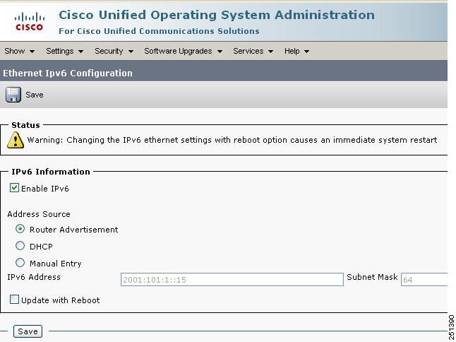
Figure 9-1 shows how to configure the IPv6 address of the server platform by using the Cisco Unified Operating System Administration GUI. To set the address, select Settings > IP > Ethernet IPv6.
Figure 9-1 Configuring the Server Platform IPv6 Address in Cisco Unified Operating System Administration
Configuring Unified CM Server IPv6 Addresses in Unified CM Administration
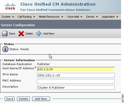
After you configure the server platform IPv6 address, define the IPv6 address for each Unified CM server by using Cisco Unified CM Administration. Select System > Server, and enter the IPv6 address in the IPv6 Name field (see Figure 9-2). This IPv6 address allows SCCP phones to retrieve the IPv6 address of this Unified CM from the configuration file downloaded from the TFTP server.
Figure 9-2 Configuring the Unified CM Server IPv6 Address in Unified CM Administration
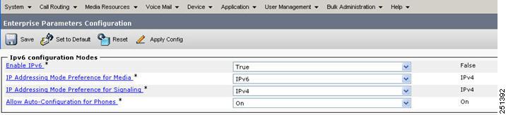
Cluster-Wide IPv6 Configuration
You can configure the following cluster-wide IPv6 settings for each Unified CM server through the Enterprise Parameters page for IPv6 Configuration Modes in Unified CM Administration (see Figure 9-3):
•
•
•
•
Figure 9-3 Cluster-Wide IPv6 Configuration Modes
Enable IPv6
Set this parameter to True to enable IPv6. The default setting is False.
IP Addressing Mode Preference for Media
This parameter has two setting options:
•
•
This cluster-wide IP Addressing Mode Preference for Media is different than the device-level IP addressing mode, and it serves two purposes:
•
•
MTP resource allocation is discussed in detail in the chapter on Media Resources and Music on Hold, page 8-1.
IP Addressing Mode Preference for Signaling
The cluster-wide IP Addressing Mode Preference for Signaling setting is used by devices whose IP Addressing Mode Preference for Signaling is set to Use System Default. The cluster-wide IP Addressing Mode Preference for Signaling has two setting options:
•
•
Allow Auto-Configuration for Phones
The cluster-wide setting of Allow Auto-Configuration for Phones is used by phones whose Allow Auto-Configuration for Phones parameter is set to Default. Allow Auto-Configuration for Phones has two settings:
•
•
Unified CM Server Hardware Platforms
All standard Unified CM hardware platforms are capable of supporting IPv6. Unified CM clusters utilize various types of servers, depending on the scale, performance, and redundancy required. They range from non-redundant, single-processor servers to highly redundant, multi-processor units. For a list of the general types of servers you can use in a Unified CM cluster, along with their main characteristics, refer to the Cisco Unified Communications Solution Reference Network Design (SRND), available at http://www.cisco.com/go/ucsrnd.
NIC Teaming for Network Fault Tolerance
NIC teaming for Network Fault Tolerance with Cisco Unified CM is supported for IPv6 on Hewlett-Packard and IBM server platforms with dual Ethernet network interface cards (NICs). This feature allows a server to be connected to the Ethernet through two NICs and, hence, two cables. NIC teaming prevents network downtime by transferring the workload from the failed port to the working port. NIC teaming cannot be used for load balancing or increasing the interface speed.
Intra-Cluster Communications
There are two primary types of intra-cluster communications, database replication and Intra-Cluster Communication Signaling (ICCS), both of which support IPv4 only.
TFTP Server
Within any Cisco Unified CM system, endpoints such as IP phones rely on a TFTP process to acquire configuration files, software images, and other endpoint-specific information. The Cisco TFTP service is a file serving system that can run on one or more Unified CM servers. It builds configuration files and serves firmware files, ringer files, device configuration files, and so forth, to endpoints.
When IPv6 is enabled in the Unified CM cluster, the TFTP server inherits its IPv6 server address from the configured server address. This allows the TFTP server to serve files to devices using IPv6 signaling.
Unified CM CTI
Unified CM's CTI interface is IPv6-aware. This means that the CTI interface communicates with IPv4 addresses, but it can receive and understand IPv6 addresses embedded in application protocol data units (PDUs).
Unified CM AXL/SOAP
Unified CM's Administrative XML (AXL) Simple Object Access Protocol (SOAP) interface is IPv6-aware. This means that the AXL/SOAP interface communicates with IPv4 addresses, but it can receive and understand IPv6 addresses embedded in application protocol data units (PDUs).
SNMP
Simple Network Management Protocol (SNMP) for Unified CM is IPv6-aware and communicates with IPv4 addresses, but it can receive and understand IPv6 addresses embedded in application protocol data units (PDUs). The SNMP Management Information Base (MIB) for Unified CM supports IPv6 addresses for IPv6-only IP phones and for dual-stack phones.
Cisco Unified Communications Applications
The majority of Cisco Unified Communications applications support IPv4 addressing only. The exception to this is Cisco Unified Provisioning Manager, which is IPv6-aware.
Unified CM Platform Capacity Planning
IPv6 addresses require additional Unified CM server memory when compared with IPv4 addresses. With respect to this additional overhead in a Unified CM deployment with a large number of IPv6 devices, the busy hour call completion (BHCC) capacity is approximately 3% to 5% less than the capacity of IPv4-only deployments.
Interoperability of Unified CM and Unified CM Express
Cisco Unified Communications Manager Express (Unified CME) supports IPv4-only. If you are deploying Unified CME with Unified CM, follow the design guidance in the Cisco Unified Communications Solution Reference Network Design (SRND), available at http://www.cisco.com/go/ucsrnd.
Call Admission Control
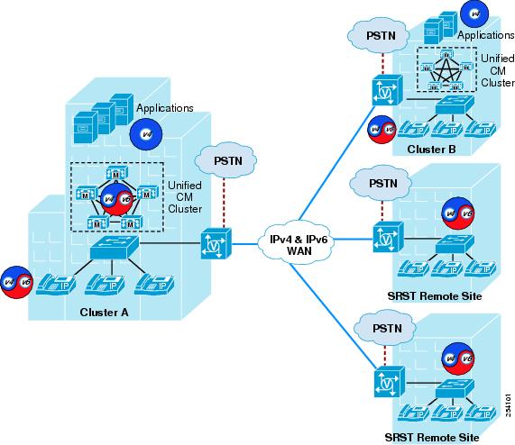
IPv6-enabled Cisco Unified CM 8.0 supports single-site deployments, multi-site WAN deployments with distributed call processing, and multi site deployments with centralized call processing. Call admission control is required where calls are made over a WAN between remote sites on the same cluster or between Cisco Unified CM clusters (see Figure 9-4).
Figure 9-4 Multi-Site Unified Communications Deployment
Call Admission Control with Unified Communications IPv6 Deployments
Unified Communications IPv6 deployments with Cisco Unified CM 8.0 support locations-based topology-unaware call admission control only for calls between remote sites in the same cluster and over intercluster trunks. Topology-unaware call admission control requires the WAN to be hub-and-spoke, or a spokeless hub in the case of a Multiprotocol Label Switching (MPLS) virtual private network (VPN). This topology ensures that call admission control, provided by the locations configuration mechanism in Unified CM, works properly in keeping track of the bandwidth available between any two sites in the WAN. For general guidance on topology-unaware call admission control, refer to the Cisco Unified Communications Solution Reference Network Design (SRND), available at http://www.cisco.com/go/ucsrnd.
Topology-aware Resource Reservation Protocol (RSVP) cannot be used within the cluster or between clusters as a call admission control technique. For IPv6-enabled Unified CM clusters, this means the following:
•
•
•
•
For IPv6 traffic, Unified CM uses the values shown in Table 5-1 in its locations-based call admission control algorithm.
Locations-Based Call Counting Call Admission Control
Cisco Unified CM 8.0 also supports a type of locations-based, topology-unaware call admission control known as call counting. Less sophisticated than standard Unified CM locations-based call admission control, call counting uses a fixed bandwidth value for each voice and video call, irrespective of the codec or actual bandwidth used.
For call counting, the following default values are used for Layer 3 voice and video bandwidth when calculating the amount of available bandwidth at a location:
•
•
Although call counting provides a simplified form of call admission control, it also has the disadvantage that bandwidth reserved for voice and video in the WAN might not be used efficiently.
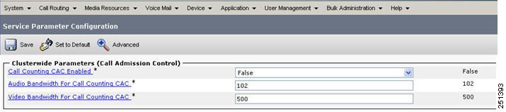
To enable call counting in Unified CM Administration, select Service Parameters > Clusterwide Parameters (Call Admission Control). (See Figure 9-5.) The default setting for Call Counting CAC Enabled is False. The voice and video bandwidth values for call counting are configurable.
Figure 9-5 Configuring Call Counting
Cisco Unified Communications Manager Business Edition
Cisco Unified Communications Manager Business Edition supports IPv4 only.