-
Deploying IPv6 in Unified Communications Networks with Cisco Unified Communications Manager
-
Preface
-
Introduction
-
IPv6 Basics
-
IPv6 Support in Cisco Unified Communications Devices
-
Unified Communications Deployment Models for IPv6
-
Network Infrastructure
-
Gateways
-
Trunks
-
Media Resources and Music on Hold
-
Call Processing and Call Admission Control
-
Dial Plan
-
Applications
-
IP Video Telephony
-
IP Telephony Migration Options
-
Security
-
Unified Communications Endpoints
-
Configuring IPv6 in Cisco Unified CM
-
Configuring Cisco Integrated Services Routers
-
Configuring Cisco VG224 Analog Voice Gateway
-
Configuring Cisco IOS Gateways
-
 Feedback
Table Of Contents
IPv6 Unicast Addresses - Network and Host IDs
Unique Local Unicast Addresses
Address Assignment for IPv6 Devices
IPv6 Stateless Address Auto-Configuration (RFC2462)
IPv6 Basics
Revised: June 08, 2010; OL-19142-02
This chapter provides an introduction for those who are unfamiliar with IPv6 addressing and IPv6 services. The basics of IPv6 addressing are discussed, as are the various address types, address assignment options, new DHCP features, and DNS. For further reading on IPv6, refer to the following documentation:
•
Deploying IPv6 Networks, a Cisco Press publication available through http://www.cisco.com/web/about/ac123/ac220/about_cisco_cisco_press.html
•
•
IPv6 Addressing
An IPv6 address consists of 8 sets of 16-bit hexadecimal values separated by colons (:), totaling 128 bits in length. For example:
2001:0db8:1234:5678:9abc:def0:1234:5678
Leading zeros can be omitted, and consecutive zeros in contiguous blocks can be represented by a double colon (::). Double colons can appear only once in the address. For example:
2001:0db8:0000:130F:0000:0000:087C:140B can be abbreviated as
2001:0db8:0:130F::87C:140B
As with the IPv4 Classless Inter-Domain Routing (CIDR) network prefix representation (such as 10.1.1.0/24), an IPv6 address network prefix is represented the same way:
2001:db8:12::/64
IPv6 Unicast Addresses - Network and Host IDs
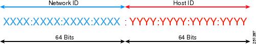
IPv6 unicast addresses generally use 64 bits for the network ID and 64 bits for the host ID, as illustrated in Figure 2-1.
Figure 2-1 IPv6 Unicast Network and Host ID Format
The network ID is administratively assigned, and the host ID can be configured manually or auto-configured by any of the following methods:
•
•
•
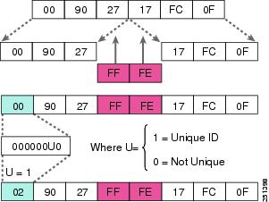
Figure 2-2 Conversion of EUI-64 MAC Address to IPv6 Host Address Format
Types of IPv6 Addresses
As with IPv4, IPv6 addresses are assigned to interfaces; however, unlike IPv4, an IPv6 interface is expected to have multiple addresses. The IPv6 addresses assigned to an interface can be any of the following types:
•
Identifies a single node or interface. Traffic destined for a unicast address is forwarded to a single interface.
•
Identifies a group of nodes or interfaces. Traffic destined for a multicast address is forwarded to all the nodes in the group.
•
Identifies a group of nodes or interfaces. Traffic destined to an anycast address is forwarded to the nearest node in the group. An anycast address is essentially a unicast address assigned to multiple devices with a host ID = 0000:0000:0000:0000. (Anycast addresses are not widely used today.)
With IPv6, broadcast addresses are no longer used. Broadcast addresses are too resource intensive, therefore IPv6 uses multicast addresses instead.
Address Scopes
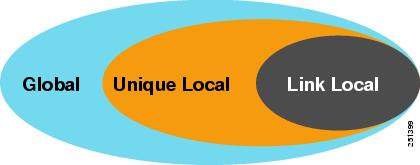
An address scope defines the region where an address can be defined as a unique identifier of an interface. These scopes or regions are the link, the site network, and the global network, corresponding to link-local, unique local unicast, and global addresses (see Figure 2-3).
Figure 2-3 IPv6 Address Scopes
Global Unicast Addresses
Global unicast addresses are:
•
•
•
•
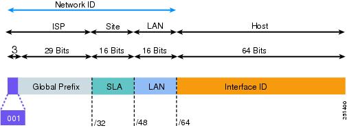
Figure 2-4 illustrates the format of a global unicast address.
Figure 2-4 Global Unicast Address Format
The global routing prefix is assigned to a service provider by the Internet Assigned Numbers Authority (IANA). The site level aggregator (SLA), or subnet ID, is assigned to a customer by their service provider. The LAN ID represents individual networks within the customer site and is administered by the customer.
The Host or Interface ID has the same meaning for all unicast addresses. It is 64 bits long and is typically created by using the EUI-64 format.
Example of a global unicast address:
2001:0DB8:BBBB:CCCC:0987:65FF:FE01:2345
Unique Local Unicast Addresses
Unique local unicast addresses are:
•
•
•
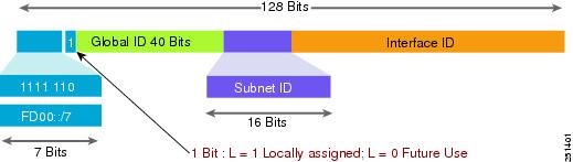
Figure 2-5 illustrates the format of a unique local unicast address.
Figure 2-5 Unique Local Unicast Address Format
Global IDs do not have to be aggregated and are defined by the administrator of the local domain. Subnet IDs are also defined by the administrator of the local domain. Subnet IDs are typically defined using a hierarchical addressing plan to allow for route summarization.
The Host or Interface ID has the same meaning for all unicast addresses. It is 64 bits long and is typically created by using the EUI-64 format.
Example of a unique local unicast address:
FD00:aaaa:bbbb:CCCC:0987:65FF:FE01:2345
Link Local Unicast Addresses
Link local unicast addresses are:
•
•
•
•
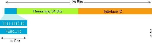
Figure 2-6 illustrates the format of a link local unicast address.
Figure 2-6 Link Local Unicast Address Format
The remaining 54 bits of the network ID could be zero or any manually configured value.
The interface ID has the same meaning for all unicast addresses. It is 64 bits long and is typically created by using the EUI-64 format.
Example of a link local unicast address:
FE80:0000:0000:0000:0987:65FF:FE01:2345
This address would generally be represented in shorthand notation as:
FE80::987:65FF:FE01:2345
IPv6 Multicast Addresses
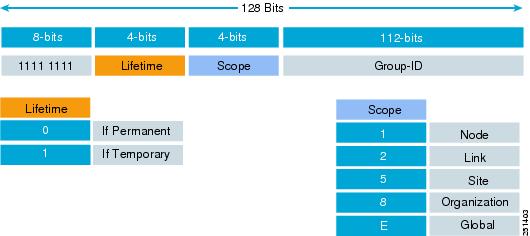
IPv6 multicast addresses have an 8-bit prefix, FF00::/8 (1111 1111). The second octet defines the lifetime and scope of the multicast address (see Figure 2-7).
Figure 2-7 Multicast Address Format
Multicast addresses are always destination addresses. Multicast addresses are used for router solicitations (RS), router advertisements (RA), DHCPv6, multicast applications, and so forth.
Note
Table 2-1 lists some well known multicast addresses.
For more information on IPv6 multicast addresses, refer to the IANA documentation available at
http://www.iana.org/assignments/ipv6-multicast-addresses
Address Assignment for IPv6 Devices
IPv6 provides the following mechanisms for assigning address to IPv6 devices:
•
Manual Configuration
An IPv6 address can be configured statically by a human operator. This can be an appropriate method of assigning addresses for router interfaces and static network elements and resources. However, manual assignment is open to errors and operational overhead due to the 128-bit length and hexadecimal attributes of the addresses.
IPv6 Stateless Address Auto-Configuration (RFC2462)
Stateless address auto-configuration (SLAAC) provides a convenient method to assign IP addresses to IPv6 nodes. This method does not require any human intervention from an IPv6 user. If you want to use IPv6 SLAAC on an IPv6 node, then it is important to connect that IPv6 node to a network with at least one IPv6 router. This router is configured by the network administrator and sends out Router Advertisement (RA) announcements onto the link. These announcements can allow the on-link connected IPv6 nodes to configure themselves with an IPv6 address and routing parameters, as specified in RFC2462, without further human intervention. With SLAAC, the node uses the IPv6 network prefix advertised in the link-local router's RAs and creates the IPv6 host ID by using the phone's MAC address and the EUI-64 format for host IDs.
DHCP for IPv6
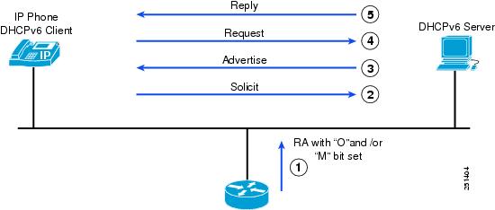
IPv6 devices use multicast to acquire IP addresses and to find DHCPv6 servers. The basic DHCPv6 client-server concept is similar to DHCP for IPv4. If a client wishes to receive configuration parameters, it will send out a request on the attached local network to detect available DHCPv6 servers. This is done through the Solicit and Advertise messages (see Figure 2-8). Well-known DHCPv6 multicast addresses are used for this process. Next, the DHCPv6 client will Request parameters from an available server, which will respond with the requested information in a Reply message. Like DHCPv4, DHCPv6 uses an architectural concept of "options" to carry additional parameters and information within DHCPv6 messages.
Figure 2-8 IPv6 DHCP operation
The DHCPv6 client knows whether to use DHCPv6 based upon the instruction from a router on its link-local network. The default gateway has two configurable bits in its Router Advertisement (RA) available for this purpose:
•
•
For details on Cisco IOS DHCP configuration, see Example Configuration for a Cisco IOS IPv6 DHCP Server, page 5-6.
Stateless DHCP
Stateless DHCPv6 is a combination of Stateless Address Auto-Configuration and Dynamic Host Configuration Protocol for IPv6, and it is specified by RFC3736. When a router sends an RA with the O bit set but does not set the M bit, the client can use Stateless Address Auto-Configuration (SLAAC) to obtain its IPv6 address and use DHCPv6 to obtain additional information (such as TFTP server address or DNS server address). This mechanism is known as Stateless DHCPv6 because the DHCPv6 server does not have to keep track of the client address bindings.
Stateful DHCP
The Dynamic Host Configuration Protocol for IPv6 (DHCPv6) has been standardized by the Internet Engineering Task Force (IETF) through RFC3315. When a router sends an RA with the M bit set, this indicates that clients should use DHCP to obtain their IP addresses. When the M bit is set, the setting of the O bit is irrelevant because the DHCP server will also return "other" configuration information together with the addresses. This mechanism is known as Stateful DHCPv6 because the DHCPv6 server does keep track of the client address bindings.
DNS for IPv6
Cisco Unified CM uses DNS name-to-address resolution in the following cases:
•
•
•
For IPv6, the principles of DNS are the same as for IPv4 (see Table 2-2), with the following exceptions:
•
•