Feedback
Table Of Contents
Originating Basic Call State Machine (CS2 Call Model)
Cisco BTS 10200 Softswitch Feature Server Strategy
Remote Activation of Call Forwarding
Integrated Services Digital Network
Generic Address Parameter Based Routing
Automatic Number Identification
Automatic Number Identification Screening
Automatic Number Identification Screening Profile
Technical Prefix Group Profile
Local Toll-Free Service Provisioning
Service Control Point Based Toll-Free Services
Automatic Number Identification White/Black List
Dial Plans and Routing
Revised: December 9, 2008, OL-8001-10Introduction
This chapter provides detailed dial plan and routing information for the Cisco BTS 10200 Softswitch. The following subjects are discussed in this chapter:
•
Originating Basic Call State Machine (CS2 Call Model)
•
•
•
•
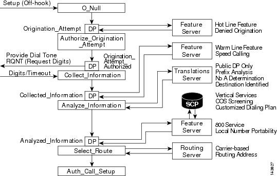
Originating Basic Call State Machine (CS2 Call Model)
This section provides detailed information on the partial originating basic call state machine (OBCSM). Refer to Figure 3-1 while reviewing the following detailed step-by-step explanation of the CS2+ call model.
Step 1
Step 2
Step 3
Step 4
Step 5
Step 6
Step 7
Step 8
Step 9
Step 10
Figure 3-1 Originating Basic Call State Machine (CS2 Call Model)
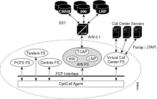
Cisco BTS 10200 Softswitch Feature Server Strategy
Figure 3-2 provides an illustrated example of the Cisco BTS 10200 Softswitch feature service strategy.
Figure 3-2 Cisco BTS 10200 Softswitch Feature Server Strategy
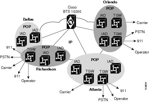
Point of Presence
Figure 3-3 provides an illustrated example of the Cisco BTS 10200 Softswitch ability to process and route calls between multiple points of presence (POPs).
Figure 3-3 Point of Presence
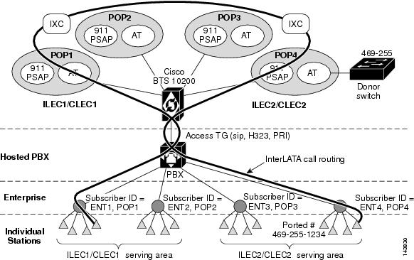
Network Configuration
Figure 3-4 provides an illustrated example of a typical Cisco BTS 10200 Softswitch network configuration.
Figure 3-4 Network Configuration
Subscriber Types
This section describes the Cisco BTS 10200 Softswitch subscriber types. The following subjects are discussed:
•
Individual
Individual is the Cisco BTS 10200 Softswitch default subscriber type. The individual subscriber type is assigned to individual subscribers.
Centrex
The Centrex (CTX) subscriber type is assigned to the main subscriber ID of a Centrex group. Additionally, Centrex subscribers types include CTXG-INDIVIDUAL subscribers, CTXG-MLHG subscribers, and CTXG-TG subscribers. CTXG-INDIVIDUAL subscriber type is assigned to a Centrex subscriber. CTXG-MLHG subscriber type is assigned to a Centrex Multi-line Hunt Group (MLHG) (for example, attendant). CTXG-TG subscriber type is assigned to a Centrex trunk group.
Interactive Voice Response
Interactive voice response (IVR) subscriber type is assigned access to a DN for IVR.
Multi-line Hunt Group
The MLHG subscriber type is assigned to the main subscriber ID of a MLHG. Additionally, MLHG subscribers types include MLHG-INDIVIDUAL subscribers and MLHG-PREF-INDIV subscribers. MLHG-INDIVIDUAL subscriber type is assigned to a subscriber within an MLHG. MLHG-PREF-INDIV subscriber type is assigned to the main subscriber ID of a preferential hunt list.
Private Branch Exchange
The private branch exchange (PBX) subscriber type is assigned to the main subscriber ID of a PBX.
Remote Activation of Call Forwarding
The remote activation of call forwarding (RACF) subscriber type is assigned access to a DN for remote activation of call forwarding.
Digit Collection
The Digit Map (digit-map) table tells a media gateway (MGW) how to collect and report dialed digits. The Call Agent uses a default digit-map id for normal digit collection unless a specific digit map ID is assigned to the subscriber. There are two types of subscribers:
•
•
POTS subscribers use a public dialing plan. Centrex subscribers use a customized dialing plan.
It is possible to create digit maps using two-digit and three-digit star code patterns. The length of the star code depends on the first digit of the star code. If the first digit is 2-3, then the star code length is three digits. If the first digit is 4-9, then the star code length is two digits.
For example:
*2-3xxx*4-9xxThe following example shows the addition of a typical digit-map allowing two-digit star codes only.
Example:
add digit-map id=default;
digit-pattern=0T|00|[2-9]11|[2-9]xx[2-9]xxxxxx|1[2-9]xx[2-9]xxxxxx|0[2-9]xx[2-9]xxxxxx|011
xxxxxx.T|01xxxxxx.T|101xxxx|#|*xx|11xx|xxxxxxxxxxxxxxxxxxx;
The following example shows the addition of a typical digit-map allowing both two- and three-digit star codes.
Example:
add digit-map id=cwd;
digit-pattern=0T|00|[2-9]11|[2-9]xx[2-9]xxxxxx|1[2-9]xx[2-9]xxxxxx|0[2-9]xx[2-9]xxxxxx|011
xxxxxxxxxxxxx.T|101xxxx|#|*[4-9]x|*[2-3]xx|11xx|[2-9]#|[2-4]x#|[2-9]T|[2-4]xT|01xxxxxxxxxx
x;
Table 3-1 describes the components of a two-digit star code digit map that is created by issuing the add digit-map command.
Caution
Specifically, you must not attempt to implement a digit pattern in which a bracket is left unbound. For example, in the syntax [1-9] xxxxx], the closing bracket is unbound. This syntax error can cause a media gateway to fail when it receives a RQNT message in which a digit pattern was incorrectly specified.
Casual Carrier Dialing
Use the following instructions to add a casual carrier entry (101xxxx + 1 + npa-nxx-xxxx) to the dial-plan.
Step 1
Step 2
Step 3
Note
Dial Plans
The following topics are discussed in this section:
National Dial Plan
The national dial plan analyzes, screens, and routes calls based on dialed digits. The National Dial Plan table holds dial plan information for a specific type of call. It defines valid dialing patterns and determines call routing. All records that share a common dial-plan-profile id are considered a dial plan.
International Dial Plan
The International Dial Plan (intl-dial-plan) table holds international dial plan information for calls to regions outside the NANP. It contains the country code, minimum and maximum digits, the country name, and the route-grp-id.
Custom Dial Plan
The Custom Dial Plan (custom-dial-plan) table translates Centrex calls. If the result of a custom dial plan (CDP) is a POTS access code, call processing uses the POTS Dial Plan table to translate the digits dialed after the POTS access code. Speed call codes are provisioned in this table as nod=speed-call and fname = SC1D (or SC2D). Screening does not apply to speed dialing.
Digit Manipulation
The Digit Manipulation (digman) table is used to perform digit and NOA manipulation. Examples of digit manipulation are:
•
•
•
•
•
Digit Analysis
This section contains information related to the dialed digit analysis. The dialed digit analysis determines the destination and routing of the placed call. The following topics are discussed:
Destination
This section contains related the placed call destination determination. The following topics are discussed:
Call Type
The Call Type (call-type) table contains the valid call types supported by the Call Agent. It is not provisionable.
Route Guide
The Route Guide (route-guide) table holds routing information based on policy-type.
Route
The Route (route) table contains a list of up to ten trunk groups to route a call. If all the trunk groups are busy or not available, call processing uses the alt-route-id (if specified) to route the call. The Element Management System (EMS) provisions the Call Agent ID field based on the Trunk Group table.
Note
Carrier
The Carrier (carrier) table defines the characteristics and capabilities supported by interLATA carriers, intraLATA carriers, international carriers, and provides routing information.
Note
Local Serving Area
The local service area (LSA) table provides extended local service. If a NANP dialed call results in an intraLATA toll or an interLATA call, and the subscriber has an LSA ID assigned, the LSA table is screened to check if the dialed digits appear in the subscriber's LSA area. If the dialed digits are found in the Lsa table, the call is converted to a local call.
Class of Service Screening
Class of service (COS) screening allows subscribers, or a group of subscribers, to have different collections of privileges and features assigned to them.
The COS Restrict (cos-restrict) table identifies the restrictions on a subscriber's class of service, including restrictions on the calls the subscriber can make (screening).
Call type and casual call screening are not performed for NANP and international operator calls, even though NANP or casual call restrictions are requested for a calling party.
Account codes are not collected for:
•
•
•
Class of call screening examples are:
•
•
•
•
•
•
•
Routing
This section provides information relating to the routing of calls by the Cisco BTS 10200 Softswitch. The following topics are discussed:
Office Code
The Office Code (office-code) table specifies the office codes assigned to a particular Call Agent. The office codes defined in this table normally terminate to a subscriber. This table defines the office-code-index (normalized office code) that is used as an index in the DN2Subscriber table.
Ported Office Code
The Ported Office Code (ported-office-code) table specifies numbers, or ranges of numbers, that might have been ported-in to this switch. If a called number matches any of the ported numbers, or is within any of the specified ranges of numbers, the Call Agent queries the DN2subscriber table to determine the current status of the DN.
Route Guide
The Route Guide (route-guide) table holds routing information based on policy-type.
Route
The Route (route) table contains a list of up to ten trunk groups to route a call. If all the trunk groups are busy or not available, call processing uses the alt-route-id (if specified) to route the call. The EMS provisions the Call Agent ID field based on the Trunk Group table.
Note
The route table enables:
•
•
•
Trunk Group
The Trunk Group (trunk-grp) table identifies the trunk group and maps it to the associated media gateway.
Trunk Group Types
The Cisco BTS 10200 Softswitch supports the following trunk group types: announcement, channel associated signaling (CAS), Integrated Services Digital Network (ISDN), Signal System 7 (SS7), and SOFTSW (Session Initiation Protocol (SIP)). The Trunk Group table defines common information based on the trunk group type. The Cisco BTS 10200 Softswitch supports announcement, CAS, ISDN, SS7 and SOFTSW trunk group profiles. The following trunk group types are discussed:
•
Announcement
The Announcement Trunk (annc-trunk) table is used when an announcement server is required in an Asynchronous Transfer Mode (ATM) network.
Channel Associated Signaling
The CAS Trunk Group Profile (cas-tg-profile) table holds common information on a CAS trunk group. It supports the following signaling types: dual tone multifrequency (DTMF) loop start, DTMF ground start, multifrequency (MF) im start, MF wink start, DTMF im start, DTMF wink start. A cas-tg-profile record can be shared by multiple CAS trunk groups.
Integrated Services Digital Network
The ISDN Trunk Group Profile (isdn-tg-profile) table holds common information regarding an ISDN trunk group. This table is used to configure the Cisco BTS 10200 Softswitch to interact with various types of private branch exchanges (PBXs) having different configurations (such as non-facility associated signaling (NFAS), facility associated signaling (FAS), and so forth), initialization procedures (service or restart), or supporting different call control or maintenance timer values. The isdn-tg-profile record can be shared by multiple ISDN trunk groups. The table tokens configure the Call Agent to communicate with a particular PBX.
Signaling System 7
The SS7 American National Standards Institute (ANSI) Trunk Group Profile (ss7-ansi-tg-profile) table holds common information regarding an SS7 trunk group such as continuity test (COT). This table can be shared by multiple SS7 trunk groups.
Session Initiation Protocol
The Softswitch (SIP) Trunk Group Profile (softsw-tg-profile) table holds all the information specific to a Softswitch trunk, such as id, protocol, indicators and echo suppression. The softsw-tg-profile record can be shared by multiple softswitch trunk groups. An ID must be created in this table before entries can be added to the Softswitch Trunk Group table.
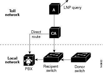
Generic Address Parameter Based Routing
Figure 3-5 shows an illustrated example of generic address parameter (GAP) based routing.
Figure 3-5 Generic Address Parameter Based Routing
Tandem Provisioning
This section provides general information on tandem provisioning. The following topics are discussed:
•
•
•
•
Automatic Number Identification
The ANI table is used for the ANI screening feature. The table keeps track of allowed/blocked status ANI. If the ANI status is blocked, the call is not allowed.
Automatic Number Identification Screening
The ANI Screening (ani-screening) table performs ANI screening on calls received over a trunk group. Normally, ANI screening is performed on calls received from a PBX (ISDN, H.323, and Session Initiation Protocol (SIP)). This table allows performing ANI-based routing in addition to ANI screening. When a record is found that matches the incoming ANI, the subscriber ID associated with the record is used for further digit analysis and routing.
Automatic Number Identification Screening Profile
The ANI Screening Profile (ani-screening-profile) table defines an id to perform ANI screening. The ID is assigned to a trunk group when ANI screening is required or when ANI-based routing is required for calls originating over a trunk group.
Cause Code Map
The Cause Code Map (cause-code-map) table processes cause codes received from an outgoing interface, and also when sending cause codes to a previous switch over an incoming interface. It also specifies why a call was released.
When used for an outgoing interface, this table serves the following purposes:
•
•
When used for an incoming interface, the table maps normalized cause codes to a cause code sent over the incoming interface. If no entry is found in the table, the Cisco BTS 10200 Softswitch uses the cause code as is.
Cause Code Map Profile
The Cause Code Map Profile (cause-code-map-profile) table defines cause code map IDs, defines default mappings to a standard cause code (Q.850), and defines default actions to take. These IDs must be provisioned before provisioning either the Cause Code table or the Trunk Group table.
H.323 Gateway
The H.323 Gateway (h323-gw) table defines the capabilities of each H.323 protocol gateway. There can be four instances of an H.323 gateway running on the Call Agent at any one time.
H.323 Gateway to Gatekeeper
The H.323 Gateway to Gatekeeper (h323-gw2gk) table describes gatekeeper characteristics for each gateway in an H.323 network. Multiple gateways can have the same gatekeeper, or there can be a different gatekeeper for each gateway. However, a gateway can be registered to one gatekeeper at a time. A gatekeeper identifies, controls, counts, and supervises gateway traffic, including, but not limited to, gateway registration, address resolution, bandwidth control, and admission control.
H.323 Terminal
The H.323 Terminal (h323-term) table holds information about H.323 terminals (such as H.323 audio/video phones) managed by the Call Agent and known in advance. This table is specific to H.323 subscribers.
H.323 Terminal Profile
The H.323 Terminal Profile (h323-term-profile) table defines the characteristics of group of H.323 terminals (or phones). An h323-term-profile id must be created in this table before any H.323 subscriber entries can be added. This table contains almost all the same fields as from the H.323 Trunk Group Profile table, except for some that are specific to trunk side (such as Generic Transparency Descriptor (GTD)).
H.323 Trunk Group Profile
The H.323 Trunk Group Profile (h323-tg-profile) table defines the characteristics of each H.323 trunk. An h323-tg-profile id must be created in this table before H.323 trunk group entries can be added.
II White Black List
The II White Black List (ii-wb-list) table allows or blocks calls from certain types of lines. The COS Restrict ID specifies if the list is to be used as a White List or Black List.
Service Provider
The Service Provider (service-provider) table is used when there are multiple service providers providing service via a single logical Call Agent.
Technical Prefix Group Profile
The Technical Prefix Group Profile (tech-prefix-grp-profile) table identifies the IDs used for the Technical Prefix Group table. These IDs must be created in this table before entries can be added to the Technical Prefix Group table.
Technical Prefix Group
The Technical Prefix Group (tech-prefix-grp) table provides a list of technical prefixes supported by a gateway. The same tech-prefix-list ID can be shared by multiple gateways. Each gateway must register the tech-prefixes supported to their respective gatekeepers.
Technical prefixes allow the inclusion of special characters in a called number. These special characters are commonly designated as a 1#, 2#, 3#, and so forth, and can be configured to prepend called number on the outgoing VoIP dial peer. The gatekeeper then checks its gateway technical prefix table for gateways registered with that particular tech prefix. Technology prefixes can also be used to identify a type, class, or pool of gateways.
The gatekeeper can be provisioned with technical prefixes in one of the following ways:
•
•
•
A group of one or more of technical prefixes can be provisioned in Cisco BTS 10200 Softswitch and this group can be associated to an H.323 gateway. The Cisco BTS 10200 Softswitch H.323 gateway process instance registers the technical prefixes from its technical prefix group with its primary gatekeeper. The technical prefix is encoded in the terminal Alias field of a registration request (RRQ) message as E.164 addresses. The gatekeeper routes calls to the Cisco BTS 10200 Softswitch H.323 gateway based on the technical prefixes.
Trunk Group Feature Data
The Trunk Group Feature Data (trunk-grp-feature-data) table performs COS screening for Tandem calls. If the received ANI is not found in the ANI table, and the casual-call flag is set to Y, the call is allowed. If the casual-call flag is set to N, the call is blocked. The cos-restrict-id performs the COS screening.
Trunk Group Service Profile
The Trunk Group Service Profile (trunk-grp-service-profile) table links a trunk group to services.
Local Toll-Free Service Provisioning
The purpose of toll-free services is to have the called party, rather than the calling party, charged for the call. These calls are prefixed with the 1+8XX service access codes. The seven digits following the 8XX codes are used for routing the call. For an inbound/outbound 8XX call, the Cisco BTS 10200 Softswitch checks the local toll-free database first. If the corresponding DN is not found in the local toll-free database, the system sends a query to the service control point (SCP) to request the corresponding DN. All aspects of toll-free calling are transparent to the caller. A caller expects to dial 1-8XX-NXX-XXXX to reach the desired destination. The company that translates the number to a specific DN, and the company that routes the call, must appear transparent to callers. Most callers are not aware that their dialed 8XX number is changed into a specific DN. What matters to the callers is that they reach what they perceive to be the called number, and they are not billed for the call.
The following additional topics are discussed in this section:
•
•
Local Toll-Free Database
The Cisco BTS 10200 Softswitch provides the ability to translate inbound/outbound 8XX numbers at the Feature Server (FS) using a local 8XX database. The 8XX service supports the following features:
•
•
•
•
•
The Cisco BTS 10200 Softswitch also supports optional dialed number identification service (DNIS) service. In an 8XX DNIS service, when a call is terminated to a PBX (call center), 4 digits are outpulsed to the PBX to identify the originally dialed 8XX number. In case of custom DNIS, up to 22 digits can be outpulsed with additional information such as:
•
•
•
When a translated number (for an original 8XX call) is received, the Analyzed Info Dial Plan (DP) triggers the FS. The Cisco BTS 10200 Softswitch looks up the DNIS and TG information for the call. The DNIS information is then outpulsed to the PBX. If an overflow condition is encountered, the call is routed to the overflow trunk. The overflow trunk can be a public switched telephone network (PSTN) trunk.
Service Control Point Based Toll-Free Services
The Cisco BTS 10200 Softswitch communicates with an SCP-based database called the toll-free database service, which contains information for routing the call. The database service provides information about the network service provider selected to complete the call, and information for translating the toll-free number to a specific 10-digit DN. The routing of the call can vary depending on the arrangements made between the toll-free subscriber and the network service provider. These arrangements can include selective routing based on the time of day, day of week, and location from which the call originates.
Automatic Number Identification White/Black List
The ANI White Black List (ani-wb-list) table performs ANI screening on 800 calls. The Customer Group specifies if the list is to be used as a White List or a Black List. A White Black List specifies whether calls are allowed to connect (white) or not allowed to connect (black).
Customer Group
The Customer Group (cust-grp) table defines the cust-grp-id and how ANI call forwarding and call restrictions are applied.
DN2 Customer Group
The DN2 Customer Group (dn2cust-grp) table provides translation of inbound/outbound 8XX (toll free) numbers to a local number and designated carrier.
II Restrict List
The II Restrict List (II-restrict-list) table restricts certain types of originating line services for a given group. The use of the list is determined by provisioning in the Customer Group table. This is a Black List (restrict) only. It cannot be a White List.
Carriers/Service Providers
This section provides general carrier/service provider information. The following subjects are discussed:
Carrier
The Carrier (carrier) table defines the characteristics and capabilities supported by interLATA carriers, intraLATA carriers, international carriers, and provides routing information.
Route Guide
The Route Guide (route-guide) table holds routing information based on policy-type. The Policy Prefix (policy-prefix) table provides information for call routing based on prefix (type of call). Typical call types include 1+ dialing, international calls, toll-free, and so on. This table is used mainly for carrier routing. The Policy Point of Presence (policy-pop) (POP) based policy routing routes a call to the nearest trunk group when there are multiple trunk groups. There are several situations where a policy POP can be used. If a Call Agent serves several POPs, each POP can have its own announcement server. A POP-specific announcement server can be more efficient than a centralized announcement server. InterLATA carriers also have a point of presence in each POP. Route interLATA or international calls to the nearest carrier location using policy POP routing. The Policy Origin Dependent Routing (policy-odr) table is used for origin-dependent routing. The numbering plan area (NPA) (or NPA-NXX) of the calling party number selects a route. If no match is found based on the calling party number, the route marked as default routes the call. The Policy Region (policy-region) table performs region-based routing. The region is derived using the Region Profile table from the Route Guide table and the calling party number ANI. If ANI is not available or the Region Profile table is not provisioned, the region assigned to the trunk group is used for trunk origination. If a record cannot be found based on the region, the record with region=default (if provisioned) is used for routing.
Circuit Code
The Circuit Code (circuit-code) table defines the circuit code value for the transit network selection (TNS) parameter. The circuit code value is defined based on the line, class of service, and call type. Special circuit code values are assigned to calls from coin or hotel motel lines. If special circuit code values are not required, the default circuit code values are based on the call type sent.
Service Provider
The Service Provider (service-provider) table is used when there are multiple service providers providing service via a single logical Call Agent.
Carrier Based Routing
Carrier based routing enables the routing of Cisco BTS 10200 Softswitch calls based on carrier. Carrier based routing provides multiple service provider support. Additionally, carrier based routing enables matching of the carrier ID and the trunk group to individual service providers. Individual dial plans can be configured for each service provider or default routing can be enabled.
Call Processing Flow
This section describes the Cisco BTS 10200 Softswitch call processing flow for calls terminating on a trunk and for calls terminating at a subscriber. The following topics are discussed:
Trunk Termination
The trunk termination call flow is:
•
•
•
•
•
•
•
•
•
Subscriber Termination
The subscriber termination call flow is:
•
•
•
•
•
•
•
•