Cisco SFS Product Family Element Manager User Guide, Release 2.9.0
About Element Manager

Table Of Contents

About Element Manager

Introduction

Element Manager Primary Display

Element Manager Menus

Element Manager Icons

Common GUI Buttons

Status Indicators

Installing Element Manager

System Requirements (All Platforms)

Linux Installation

Solaris Installation

Windows Installation

Launching Element Manager

Preparing Your Server Switch


About Element Manager


These topics describe the Element Manager Java-based user-interface (GUI) that runs on your server switch:

Introduction

Installing Element Manager

Launching Element Manager

Introduction

With Element Manager, you can manage individual server switches from an easy-to-use GUI. To run Element Manager, you must complete the following tasks:

Install the Element Manager software on a host or workstation.

Configure your server switches to support Element Manager.

Launch Element Manager on your host or workstation.

The following topics describe basic features of the Element Manager user interface:

Element Manager Primary Display

Element Manager Menus

Element Manager Icons

Common GUI Buttons

Status Indicators

Element Manager Primary Display

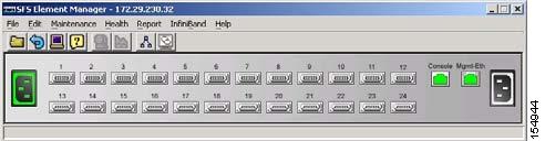
The primary display of Element Manager provides drop-down menus, feature buttons, and various clickable display elements. Figure 1-1 shows the Element Manager display.

Figure 1-1 Element Manager Primary Display

The number of menus, icons, and display elements vary by server switch platform. Table 1-1 and Table 1-2 list and describe all possible menus and buttons. Clickable display elements vary by hardware platform.

When you click a display element (such as server switch ports), a yellow border appears around the element. You can double-click any clickable element to open a related configuration window. You can right-click these elements to view element-specific menus. You can use these menus and windows to view element details or change the configuration.

You can press the Ctrl key and click multiple elements of the same type (for instance, multiple InfiniBand ports) to select multiple elements at once to configure them as a group. After you select multiple elements, right-click one of the elements to display a right-click menu for options that you can apply.

Element Manager Menus

Table 1-1 describes the drop-down menus in the Element Manager display.

Table 1-1 Element Manager Drop-down Menus 

Menu
Description

File

Use the menu items in the File menu to do the following:

Load a server switch in the Element Manager display.

Configure performance options such as intervals and thresholds for various features.

Refresh the display.

Telnet to the open server switch to configure the switch with the command-line interface (CLI). (For CLI details, see the Cisco SFS Product Family Command Reference.)

Edit

Use the Edit menu to view port properties or card properties.

Maintenance

Use the menu items in the Maintenance menu to do the following:

View server switch details.

View and configure basic services.

View and configure the boot configuration.

Back up the running configuration.

Import and export files.

Reboot the server switch.

Track diagnostic tests.

Health

Use the menu items in the Health menu to monitor the server switch status and events.

Report

Use the menu items in the Report menu to graph server switch statistics.

InfiniBand

Use the menu items in the InfiniBand menu to configure InfiniBand-specific server switch features, including the Device Manager and Subnet Manager.

Ethernet

Use the menu items in the Ethernet menu to configure Ethernet-specific server switch features.

Fibre Channel

Use the menu items in the Fibre Channel menu to configure Fibre Channel-specific server switch features.

Help

Use the menu items in the Help menu to launch the online help and locate additional help resources.


Element Manager Icons

Table 1-2 describes the feature icons in the Element Manager display.

Table 1-2 Element Manager Feature Icons 

Icon
Description

Click Open to load a different server switch in the display.

Click Refresh to poll the server switch and update the display.

Click Telnet to launch a Telnet session to the server switch.

Click Help to launch the online help.

Click Properties after you click an element (or multiple elements of the same type) to view the properties of the element(s).

Click Graph after you click an element (or multiple elements of the same type) to select element statistics that you can then graph.

Click Topology to view the server switch and neighboring devices.

Click Subnet Management to open the Subnet Management window and configure partitions, multicast groups, and other Subnet Manager-related features.

Click Storage Manager to open the Storage Manager window and configure initiators, targets, and LUNs.


Common GUI Buttons

Many windows that you can open in Element Manager display a combination of frequently appearing buttons. Table 1-3 describes these common buttons.

Table 1-3 Common Buttons 

Button
Description

Apply

Applies any changes that you made in the window to the server switch.

Refresh

Updates the window with the latest information from the server switch.

Close

Closes the window.

Help

Launches the online help.


Status Indicators

The Element Manager display uses specific colors to communicate the status of server switch elements. Table 1-4 describes status-indicator colors.

Table 1-4 Status Indicator Colors 

Color
Indication

gray

Element is not active (such as an InfiniBand port that does not connect to a cable).

red

An administrator has taken the element offline or the element experiences an error.

green

Element functions successfully.

transparent

Element is unmanaged.


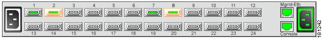
Color is also used on the primary display to indicate not only the up/down status of ports, but also the configured lane width of InfiniBand ports, as shown in Figure 1-2.

Figure 1-2 Primary View Showing Port Status

Ports 1 through 24 are InfiniBand ports.

Ports with an operational status of up show with green pins.

InfiniBand ports configured with double data rate (DDR) operational speed show with green pins and an orange surround.

InfiniBand ports configured with single data rate (SDR) operational speed appear with green pins and a grey surround.

Installing Element Manager

Element Manager runs on Linux, Solaris, and Windows platforms. Follow installation instructions for the appropriate platform:

System Requirements (All Platforms)

Linux Installation

Solaris Installation

Windows Installation

System Requirements (All Platforms)

To install Element Manager, your system must meet the following requirements:

64 MB of available RAM

75 MB of available hard disk space and 50 MB of additional available hard disk space during installation

300-MHz processor

800 x 600 screen resolution with 16-bit color depth

Linux Installation

To install Element Manager on Linux, follow these steps:


Step 1 Log in to your Linux host.

Step 2 Download the Element Manager software from the Cisco Software Download Center:

http://www.cisco.com/public/sw-center/

Step 3 Navigate to the Linux directory of the downloaded software.

Step 4 Run the appropriate binary file, and proceed with the installation wizard.


Solaris Installation

To install Element Manager on Solaris, follow these steps:


Step 1 Log in to your Solaris host.

Step 2 Download the Element Manager software from the Cisco Software Download Center:

http://www.cisco.com/public/sw-center/

Step 3 Navigate to the em/Solaris directory of the downloaded software.

Step 4 Start the ./install_yourOS.bin file. Proceed with the installation wizard.


Windows Installation

To install Element Manager on Windows, follow these steps:


Step 1 Log in to your Windows host.

Step 2 Download the Element Manager software from the Cisco Software Download Center:

http://www.cisco.com/public/sw-center/

Step 3 Navigate to the Windows directory of the downloaded software.

Step 4 Launch the executable file (em.exe) to begin the installation process.

The Introduction screen appears.

Step 5 Click Next.

The License Agreement screen appears.

Step 6 Read the license agreement, choose I accept the terms of the license agreement, and then click Next.

The Choose Install Folder screen appears.

Step 7 Select a folder, and then click Next.

The Choose Shortcut Folder screen appears.

Step 8 Make selections as appropriate for your needs, and then click Next.

The Pre-Installation Summary screen appears.

Step 9 Verify installation information in the Please Review the Following Before Continuing window, and then click Install.

The installation executes.

Step 10 Click Done when the installation completes.


Launching Element Manager

When you launch Element Manager, the interface requests the IP address (or DNS name) of the server switch that you want to manage. To successfully connect to the server switch that you want to manage, you must first configure that server switch to permit Element Manager access. If Element Manager fails to connect to a given server switch, verify that the server switch meets the prerequisites for Element Manager. See the "Preparing Your Server Switch" section.

Preparing Your Server Switch

Factory defaults permit your server switch to connect to Element Manager. The following settings must apply to your server switch to open in Element Manager:

HTTP server enabled

Telnet server enabled

SNMP server configured

To view your server switch settings, follow these steps:


Step 1 Log in to your server switch.

Step 2 Enter the enable command to enter privileged EXEC mode.

Step 3 Enter the configure terminal command to enter global configuration mode.

Step 4 Enter the ip http server command to enable the HTTP server.

Step 5 Enter the Telnet enable command to enable Telnet services.

Step 6 To configure the SNMP server, enter the snmp-server command with the following:

IP address of the server that you want to configure

(Optional) recv-event-traps keyword

For more information, see the Cisco SFS Product Family Command Reference.