-
Cisco SFS Product Family Element Manager User Guide, Release 2.9.0
-
Index
-
Preface
-
About Element Manager
-
Chassis Display Tasks
-
File Tasks
-
Edit Tasks
-
Maintenance Tasks
-
Health Tasks
-
Report Tasks
-
InfiniBand Subnet Management Tasks
-
InfiniBand Performance Management Tasks
-
InfiniBand Performance Management Tasks
-
InfiniBand Device Management Tasks
-
Ethernet Menu Tasks
-
FibreChannel Menu Tasks
-
Help Menu Tasks
-
InfiniBand Concepts
-
 Feedback
Table Of Contents
InfiniBand Subnet Management Tasks
Viewing and Managing Subnet Manager Properties
Viewing Subnet Manager Properties
Configuring Subnet Manager Properties
Configuring Subnet Manager Priority
Configuring the Sweep Interval
Configuring the Master Poll Interval
Configuring the Number of Master Poll Retries
Configuring the Maximum Supported Number of Active Standby Subnet Managers
Configuring Switch Link HoQ Life
Configuring Wait Report Response
Configuring Subnet Administrator MAD Queue Depth
Viewing and Managing Database Synchronization
Viewing Database Synchronization
Configuring Database Synchronization
Enabling Subnet Manager Database Synchronization
Configuring the Maximum Number of Backup Subnet Managers to Synchronize
Configuring the Cold Synchronization Timeout Value
Configuring the Cold Synchronization Limit Value
Configuring the Cold Synchronization Limit Period
Configuring the New Session Delay
Configuring the Resynchronization Interval
Viewing the Database Synchronization State
Viewing and Managing Nodes and Ports
Routing Around Nodes and Ports
Viewing and Managing Partitions
Enabling or Disabling IPoIB for a Partition
Adding Full Members to a Partition
Adding Available Members to a Partition
Adding Unavailable Members to a Partition
Adding Limited Members to a Partition
Adding Available Limited Members
Viewing and Managing Multicast Groups
Viewing Multicast Group Details
Viewing Multicast Group Members
Configuring IPoIB Broadcast Multicast Groups
Viewing and Managing InfiniBand Routes
Routing Around Components in an InfiniBand Network
Viewing Route-Around Information
Adding Routes to the Route-Around Table
Removing Routes from the Route-Around Table
Viewing Other Subnet Managers Information
Viewing Multicast Forwarding Information
Viewing Linear Forwarding Information
InfiniBand Subnet Management Tasks
These topics describe the InfiniBand menu subnet management tasks for Element Manager:
•
Viewing and Managing Subnet Manager Properties
•
•
•
•
•
•
Note
Using the InfiniBand Menu
The InfiniBand menu has two choices for performing InfiniBand subnet management tasks:
•
•
These topics describe how to use the Subnet Management menu option. Most of the tasks can also be performed by selecting the Subnet Management (tabular format) menu option, which presents information and configurable options in tables, but is a less user friendly way to perform your InfiniBand subnet management tasks.
Viewing and Managing Subnet Manager Properties
These topics describe procedures for performing the following tasks:
•
•
Viewing Subnet Manager Properties
To view Subnet Manager properties, follow these steps:
Step 1
The Subnet Manager window opens.
Step 2
A table of Subnet Manager properties appears under the General tab. Table 8-1 describes the fields.
See the "Configuring Subnet Manager Properties" procedure for details on how to configure these properties.
Adding a Subnet Manager
To add a Subnet Manager to your server switch, follow these steps:
Step 1
The Subnet Management window opens.
Step 2
The Subnet Managers display appears in the right pane of the window.
Step 3
The Add Subnet Manager window opens.
Step 4
Step 5
Step 6
Step 7
Step 8
The new Subnet Manager appears in the Summary table in the Subnet Managers display.
Removing a Subnet Manager
To remove a Subnet Manager from your server switch, follow these steps:
Step 1
The Subnet Management window opens.
Step 2
The Subnet Managers display appears in the right pane of the window.
Step 3
Step 4
The entry disappears from the display and the server switch configuration.
Configuring Subnet Manager Properties
The Subnet Managers navigation menu provides tuning for a number of system-wide attributes. These topics explain each attribute and describe how to configure it:
•
•
•
•
•
•
•
•
•
Configuring Subnet Manager Priority
Every Subnet Manager in the InfiniBand network carries a priority value, and at any given time the Subnet Manager with the highest integer value priority becomes the master Subnet Manager. To configure the Subnet Manager priority on your server switch, follow these steps:
Step 1
The Subnet Management window opens. Each Subnet Manager appears in the navigation pane with a Subnet Manager icon (
).
Step 2
A table of subnet manager properties appears under the General tab.
Step 3
The integer value 15 has the highest priority.
Step 4
Configuring the Sweep Interval
The sweep interval specifies how frequently the Subnet Manager queries the InfiniBand fabric for network changes. To configure the sweep interval on your server switch, follow these steps:
Step 1
The Subnet Management window opens. Each Subnet Manager appears in the navigation pane with a Subnet Manager icon (
).
Step 2
A table of subnet manager properties appears under the General tab.
Step 3
This interval represents the number of seconds between sweeps.
Step 4
Configuring Response Timeout
The response timeout of a Subnet Manager specifies the maximum amount of time that the Subnet Manager waits for a response after it sends a packet to a port. If the Subnet Manager does not receive a response in the response-time interval, the Subnet Manager identifies the port as unresponsive. To configure the response timeout, follow these steps:
Step 1
The Subnet Management window opens. Each Subnet Manager appears in the navigation pane with a Subnet Manager icon (
).
Step 2
A table of subnet manager properties appears under the General tab.
Step 3
The Subnet Manager measures the response timeout in milliseconds.
Step 4
Configuring the Master Poll Interval
The master poll interval determines the interval at which the slave Subnet Manager polls the master to see if the master still runs. To configure the master poll interval, follow these steps:
Step 1
The Subnet Management window opens. Each Subnet Manager appears in the navigation pane with a Subnet Manager icon (
).
Step 2
A table of subnet manager properties appears under the General tab.
Step 3
The value represents the interval, in seconds.
Step 4
Configuring the Number of Master Poll Retries
Master poll retries specifies the number of unanswered polls that cause a slave to identify a master as dead. To specify this value, follow these steps:
Step 1
The Subnet Management window opens. Each Subnet Manager appears in the navigation pane with a Subnet Manager icon (
).
Step 2
A table of subnet manager properties appears under the General tab.
Step 3
Step 4
Configuring the Maximum Supported Number of Active Standby Subnet Managers
Note
To configure the maximum number of active standby Subnet Managers that the master Subnet Manager supports, follow these steps:
Step 1
The Subnet Management window opens. Each Subnet Manager appears in the navigation pane with a Subnet Manager icon (
).
Step 2
A table of subnet manager properties appears under the General tab.
Step 3
Step 4
Configuring LID Mask Control
Local ID mask control assigns the number of path bits present in the base LID to each channel adapter port. Increasing the LMC value increases the number of LIDs assigned to each port to increase the number of potential paths to reach each port. To configure LID mask control, follow these steps:
Step 1
The Subnet Management window opens. Each Subnet Manager appears in the navigation pane with a Subnet Manager icon (
).
Step 2
A table of subnet manager properties appears under the General tab.
Step 3
Step 4
Configuring Switch Lifetime
Switch lifetime is one parameter that governs the transmitter packet discard policy of switches in the subnet. It determines the lifetime of packets in a switch from the point of ingress to egress. If this parameter is set to 20 or greater, then switch lifetimes are infinite (default). See InfiniBand Architecture Release 1.2, Volume 1 for more information.
Step 1
The Subnet Management window opens. Each Subnet Manager appears in the navigation pane with a Subnet Manager icon (
).
Step 2
A table of subnet manager properties appears under the General tab.
Step 3
Step 4
Configuring Switch Link HoQ Life
Switch link head of queue life determines how long an InfiniBand packet lives at the head of a switch port VL queue before it is discarded. If this parameter is set to 20 or greater, then HoQ lifetimes are infinite (default). See InfiniBand Architecture Release 1.2, Volume 1 for more information.
Step 1
The Subnet Management window opens. Each Subnet Manager appears in the navigation pane with a Subnet Manager icon (
).
Step 2
A table of subnet manager properties appears under the General tab.
Step 3
Step 4
Configuring Maximum Hop Count
We recommend that InfiniBand switch elements be connected so that all paths between any pair of switch elements are the same distance (same number of hops), if possible.
The range of values is from 0 to 64. Default is 64. A value of 0 causes the Subnet Manager to calculate and use the lowest possible value that will still ensure connectivity between all endpoints.
Note
To configure the maximum number of hops for an InfiniBand Subnet Manager, follow these steps:
Step 1
The Subnet Management window opens. Each Subnet Manager appears in the navigation pane with a Subnet Manager icon (
).
Step 2
A table of subnet manager properties appears under the General tab.
Step 3
Step 4
Configuring MAD Retries
MAD retries specifies the number of times that a Subnet Manager resends a management datagram after not receiving a response. The default value is 5.
To configure MAD retries, follow these steps:
Step 1
The Subnet Management window opens. Each Subnet Manager appears in the navigation pane with a Subnet Manager icon (
).
Step 2
A table of subnet manager properties appears under the General tab.
Step 3
Step 4
Configuring Node Timeout
Node Timeout is the minimum amount of time in seconds that a HCA is unresponsive before the Subnet Manager removes it from the InfiniBand fabric. The default value is 10 seconds.
To configure the node timeout, follow these steps:
Step 1
The Subnet Management window opens. Each Subnet Manager appears in the navigation pane with a Subnet Manager icon (
).
Step 2
A table of subnet manager properties appears under the General tab.
Step 3
Step 4
Configuring Wait Report Response
Wait Report Response configures whether or not a Subnet Manager waits to receive ReportResponse MADs in response to the Report MAD that it forwards. If you set this Boolean value to false, the Subnet Manager only sends the Report MADs once; if you set it to true, the Subnet Manager will continue to send the Report MADs until either the Report Response MAD is received or the maximum number of Report MADs have been sent. The default value is false.
To configure the wait report response, follow these steps:
Step 1
The Subnet Management window opens. Each Subnet Manager appears in the navigation pane with a Subnet Manager icon (
).
Step 2
A table of subnet manager properties appears under the General tab.
Step 3
Step 4
Configuring Subnet Administrator MAD Queue Depth
This procedure configures the size of a Subnet Administrator internal queue for receiving MADs. The default value is 256.
To configure the Subnet Administrator MAD queue depth, follow these steps:
Step 1
The Subnet Management window opens. Each Subnet Manager appears in the navigation pane with a Subnet Manager icon (
).
Step 2
A table of subnet manager properties appears under the General tab.
Step 3
Step 4
Viewing and Managing Database Synchronization
Element Manager provides multiple screens that you can use to view and configure database synchronization. This section describes the following tasks:
•
•
Viewing Database Synchronization
To view database synchronization details, follow these steps:
Step 1
The Subnet Manager window opens.
Step 2
Step 3
Details appear in the table below the tab. Table 8-2 describes the fields.
Note
Configuring Database Synchronization
The database synchronization feature propagates information from the database of the master Subnet Manager to the standby Subnet Managers. These topics describe how to configure this feature:
•
•
•
•
•
•
•
•
•
•
Enabling Subnet Manager Database Synchronization
If you are configuring more than one InfiniBand chassis in your fabric, it is likely that you will want to enable database synchronization of the Subnet Managers.
Note
To enable Subnet Manager database synchronization to update standby Subnet Managers with information from the master Subnet Manager, follow these steps:
Step 1
The Subnet Management window opens.
Step 2
Each Subnet Manager appears in the navigation pane with a Subnet Manager icon (
).
Step 3
Step 4
Step 5
Configuring the Maximum Number of Backup Subnet Managers to Synchronize
To configure the maximum number of backup Subnet Managers that will synchronize with the master Subnet Manager, follow these steps:
Step 1
The Subnet Management window opens.
Step 2
Each Subnet Manager appears in the navigation pane with a Subnet Manager icon (
).
Step 3
Step 4
Step 5
Configuring a Session Timeout
To configure the session timeout interval, in seconds, during which a synchronization session status MAD packet must arrive at the master Subnet Manager to maintain synchronization, follow these steps:
Step 1
The Subnet Management window opens.
Step 2
Each Subnet Manager appears in the navigation pane with a Subnet Manager icon (
).
Step 3
Step 4
This value determines the timeout duration, in seconds.
Step 5
Configuring the Poll Interval
To configure the interval, in seconds, at which the master Subnet Manager polls an active slave Subnet Manager to verify synchronization, follow these steps:
Step 1
Step 2
Step 3
Each Subnet Manager appears in the navigation pane with a Subnet Manager icon (
).
Step 4
Step 5
This value sets the poll interval, in seconds.
Step 6
Configuring the Cold Synchronization Timeout Value
To configure the amount of time, in seconds, that a cold synchronization tries to initiate before it times out, follow these steps:
Step 1
The Subnet Management window opens.
Step 2
Each Subnet Manager appears in the navigation pane with a Subnet Manager icon (
).
Step 3
Step 4
This value sets the timeout interval, in seconds.
Step 5
Configuring the Cold Synchronization Limit Value
To configure the maximum number of cold synchronizations to perform during a given cold synchronization period, follow these steps:
Step 1
The Subnet Management window opens.
Step 2
Each Subnet Manager appears in the navigation pane with a Subnet Manager icon (
).
Step 3
Step 4
This value sets the maximum number of synchronizations that can occur during the synchronization period. (See "Configuring the Cold Synchronization Limit Period" section.)
Step 5
Configuring the Cold Synchronization Limit Period
To specify the length of the interval during which cold synchronizations may occur, follow these steps:
Step 1
The Subnet Management window opens.
Step 2
Each Subnet Manager appears in the navigation pane with a Subnet Manager icon (
).
Step 3
Step 4
This value sets the length of the interval during which cold synchronizations may occur.
Step 5
Configuring the New Session Delay
To configure the amount of time that the master Subnet Manager waits before it attempts to initiate a synchronization session with a new Subnet Manager, follow these steps:
Step 1
The Subnet Management window opens.
Step 2
Each Subnet Manager appears in the navigation pane with a Subnet Manager icon (
).
Step 3
Step 4
This value determines the amount of time, in seconds, that the master Subnet Manager waits before it attempts to initiate a synchronization session with a new Subnet Manager.
Step 5
Configuring the Resynchronization Interval
To specify the interval at which the master Subnet Manager sends a resynchronization request to all active synchronization sessions, follow these steps:
Step 1
The Subnet Management window opens.
Step 2
Each Subnet Manager appears in the navigation pane with a Subnet Manager icon (
).
Step 3
Step 4
This value specifies the interval, in seconds, at which the master Subnet Manager sends a resynchronization request to all active synchronization sessions.
Step 5
Viewing the Database Synchronization State
To view the database synchronization state and verify that the master Subnet Manager and slave Subnet Manager(s) are synchronized, follow these steps:
Step 1
The Subnet Management window opens. Each Subnet Manager appears in the navigation pane with a Subnet Manager icon (
).
Step 2
Step 3
Step 4
Viewing and Managing Nodes and Ports
This section provides procedures for performing the following tasks:
•
Viewing Node Information
To view Subnet Manager node information, follow these steps:
Step 1
The Subnet Management window opens. Each Subnet Manager appears in the navigation pane with a Subnet Manager icon (
).
Step 2
Step 3
The Nodes in Subnet tab displays the Node GUID, Type, Description, Number of Ports, System Image GUID, and the Vendor ID information. See Table 8-3 for details.
Step 4
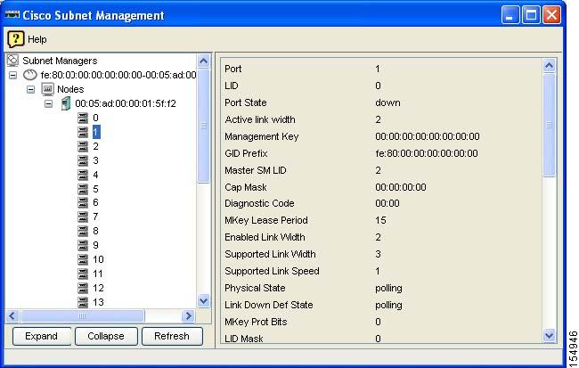
Viewing Port Information
To view information about specific ports, follow these steps:
Step 1
The Subnet Management window opens. Each Subnet Manager appears in the navigation pane with a Subnet Manager icon (
).
Step 2
Step 3
Step 4
Step 5
Step 6
Figure 8-1 Individual Port Information
Routing Around Nodes and Ports
These topics describe how to route around nodes and ports using the Nodes displays:
For a complete discussion of routing around components, including routing around chassis, see the "Routing Around Components in an InfiniBand Network" section.
Routing Around Nodes
To route around a node or to re-include a node that had previously been excluded, follow these steps:
Step 1
The Subnet Management window opens. Each Subnet Manager appears in the navigation pane with a Subnet Manager icon (
).
Step 2
Step 3
A list of nodes managed by the subnet manager appears in the left pane.
Step 4
Step 5
Step 6
Routing Around Ports
To route around a port, follow these steps:
Step 1
The Subnet Management window opens. Each Subnet Manager appears in the navigation pane with a Subnet Manager icon (
).
Step 2
Step 3
A list of nodes managed by the subnet manager appears in the left pane.
Step 4
Step 5
Step 6
Step 7
Viewing and Managing Partitions
This section provides procedures for performing the following tasks:
•
•
•
Viewing Partitions
To view the partitions on your InfiniBand network, follow these steps:
Step 1
The Subnet Management window opens.
Step 2
The navigation menu expands.
Step 3
) branch.
The partitions summary appears in the right pane. Table 8-5 describes the fields in this pane.
Creating a Partition
To create an InfiniBand partition, follow these steps:
Step 1
The Subnet Management window opens.
Step 2
Step 3
) branch.
Step 4
The Add Partition window opens.
Step 5
Step 6
Step 7
Removing a Partition
To delete a partition, follow these steps:
Step 1
The Subnet Management window opens.
Step 2
Step 3
) branch.
Step 4
Enabling or Disabling IPoIB for a Partition
Disabling IPoIB removes all current multicast group members and prevents further multicast joins. To enable or disable IPoIB on a partition, follow these steps:
Step 1
The Subnet Management window opens.
Step 2
The navigation menu expands.
Step 3
) branch.
The partitions summary appears in the right pane.
Step 4
Step 5
The Add Partition window opens.
Step 6
Step 7
Viewing Partition Details
To view partition details, follow these steps:
Step 1
The Subnet Management window opens.
Step 2
Step 3
) branch to display all partitions.
Step 4
The members (full and limited) of the partition appear in the display.
Note
Adding Full Members to a Partition
Full members of a partition can communicate to other full members and to limited members.
These topics describe how to add full members to a partition:
•
•
Adding Available Members to a Partition
To add available members to a partition, follow these steps:
Step 1
The Subnet Management window opens.
Step 2
Step 3
) branch to display all partitions in the navigation menu.
Step 4
The members (full and limited) of the partition appear in the display.
Step 5
Adding Unavailable Members to a Partition
To add unavailable members (members that do not appear in the Available Members pool) to a partition, follow these steps:
Step 1
The Subnet Management window opens.
Step 2
Step 3
) branch to display all partitions in the navigation menu.
Step 4
The members (full and limited) of the partition appear in the display.
Step 5
The Add Other Partition Member window opens.
Step 6
Step 7
Step 8
Adding Limited Members to a Partition
Limited members of a partition can communicate with full members of the partition but not with other limited members.
These topics describe how to add limited members to a partition:
•
Adding Available Limited Members
To add available limited members to a partition, follow these steps:
Step 1
The Subnet Management window opens.
Step 2
The navigation menu expands.
Step 3
) branch to display all partitions in the navigation menu.
Step 4
The members (full and limited) of the partition appear in the display.
Step 5
Adding Unavailable Members
To add an unavailable member (member does not appear in the Available Members pool) to a partition, follow these steps:
Step 1
The Subnet Management window opens.
Step 2
Step 3
) branch to display all partitions in the navigation menu.
Step 4
The members (full and limited) of the partition appear in the display.
Step 5
The Add Other Partition Member window opens.
Step 6
Step 7
Step 8
Viewing and Managing Multicast Groups
This section provides procedures for performing the following tasks:
•
•
•
Viewing Multicast Groups
To view the multicast groups on your InfiniBand network, follow these steps:
Step 1
The Subnet Management window opens.
Step 2
The navigation menu expands.
Step 3
) branch.
The multicast groups summary appears in the right pane. Table 8-6 describes the fields in this pane.
Viewing Multicast Group Details
To view multicast group details, follow these steps:
Step 1
The Subnet Management window opens.
Step 2
The navigation menu expands.
Step 3
) branch to display all groups in the navigation menu.
Step 4
Multicast group details appear in the display. Table 8-7 describes the fields in this display.
Viewing Multicast Group Members
To view multicast group members, follow these steps:
Step 1
The Subnet Management window opens.
Step 2
The navigation menu expands.
Step 3
) branch to display all groups in the navigation menu.
Step 4
Multicast group members appear in a table at the bottom of the display. Table 8-8 describes the fields in this display.
Configuring Multicast Groups
To configure multicast groups, follow these steps:
Step 1
The Subnet Manager window opens.
Step 2
Step 3
Step 4
Step 5
Step 6
Step 7
Step 8
Step 9
Step 10
Step 11
Step 12
Note
Configuring IPoIB Broadcast Multicast Groups
To configure IPoIB broadcast multicast groups, follow these steps:
Step 1
The Subnet Manager window opens.
Step 2
Step 3
Step 4
Step 5
Step 6
Step 7
Step 8
Step 9
Step 10
Step 11
Step 12
Note
Viewing InfiniBand Services
To view the InfiniBand services that run on your server switch, follow these steps:
Step 1
The Subnet Management window opens.
Step 2
Step 3
) branch.
Details of InfiniBand services appear in the right pane. Table 8-9 describes the fields in the Summary section of the pane.
Table 8-10 describes the fields in the Services Details section of the display.
Viewing and Managing InfiniBand Routes
This section provides procedures for performing the following tasks:
•
•
Viewing InfiniBand Routes
To view the route between a pair of LIDs in the InfiniBand fabric, follow these steps:
Step 1
The Subnet Management window opens.
Step 2
Step 3
) branch.
Step 4
InfiniBand routes fields appear in the right pane.
Step 5
Step 6
Step 7
Step 8
Table 8-11 describes the fields under the Switch Route tab.
Table 8-11 Switch Route Field Descriptions
Node GUID
Global unique ID of the node.
In Port
Port of ingress.
Out Port
Port of egress.
Step 9
Table 8-12 describes the fields under the Switch Element Route tab.
Table 8-12 Switch Element Route Field Descriptions
Chassis GUID
Global unique ID of the node.
In Port
Port of ingress.
Out Port
Port of egress.
Routing Around Components in an InfiniBand Network
To route around a chassis, nodes, or ports that are accumulating errors or to route around a component that you want to remove, follow the steps outlines in the subsections that follow.
Uses of this feature include the following:
•
•
Caution
Note
These topics describe how to route around components in an InfiniBand network:
•
•
•
Viewing Route-Around Information
To view active route-around operations, follow these steps:
Step 1
The Subnet Management window opens.
Step 2
Step 3
) branch.
Step 4
Excluded routes appear in the right pane. Table 8-13 describes the fields in the pane.
Adding Routes to the Route-Around Table
To add a component to the route-around table, follow these steps:
Step 1
The Subnet Management window opens.
Step 2
Step 3
) branch.
Step 4
Step 5
A Route Around dialog box appears.
Step 6
a.
b.
c.
Step 7
Removing Routes from the Route-Around Table
To remove a route-around from the table, follow these steps.
Step 1
The Subnet Management window opens.
Step 2
Step 3
) branch.
Step 4
Step 5
Step 6
Viewing Other Subnet Managers Information
To view information on other Subnet Managers in the network, follow these steps:
Step 1
The Subnet Management window opens.
Step 2
The navigation menu expands.
Step 3
The Port GUID, Priority, and Subnet Manager state information appears in the right pane.
Table 8-14 describes the fields in the Details pane.
Note
Viewing Event Subscriptions
To view the Subnet Management event subscriptions information, follow these steps:
Step 1
The Subnet Management window opens.
Step 2
The navigation menu expands.
Step 3
The LID, Node GUID, and Port Number information appears in the right pane.
Table 8-15 describes the fields under Subnet Management Event Subscriptions Details.
Viewing Forwarding Tables
This section provides procedures for performing the following tasks:
•
•
Viewing Multicast Forwarding Information
To view the multicast forwarding configuration, follow these steps:
Step 1
Step 2
Table 8-16 describes the information that appears.
Viewing Linear Forwarding Information
To view the linear forwarding configuration, follow these steps:
Step 1
Step 2
Table 8-17 describes the displayed fields.
Table 8-17
Linear Forwarding Entries