Table Of Contents
InfiniBand Topology View Tasks
Launching the Topology View
Viewing Internal Server Switch Components and TCAs
Viewing Subnet Details
Viewing Nodes
Viewing Ports
Viewing Switches
Viewing Neighboring Ports
Viewing Subnet Management Agents
Viewing Subnet Manager Node Details
Viewing Subnet Manager Switch Details
Viewing Subnet Manager Agent Switch Cap Details
Viewing Subnet Manager Agent Ports(1) Details
Viewing Subnet Manager Agent Ports (2) Details
Viewing Subnet Manager Multicast Details
Viewing Subnet Manager Agent Linear Forwarding Table Details
Viewing the Subnet Manager Agent Partition Details
Viewing the Subnet Manager Agent SLVL Map
InfiniBand Topology View Tasks
These topics describe the InfiniBand menu tasks that can be performed through the Element Manager Topology view:
• Launching the Topology View
•Viewing Subnet Details
•Viewing Subnet Management Agents
Note This section provides information to familiarize you with the InfiniBand technology. For hardware-specific information, consult the relevant hardware documentation.
Launching the Topology View
This topic describes launching the topology view. To view specific server switch components or TCS, see Viewing Internal Server Switch Components and TCAs.
To launch the topology view, follow these steps:
Step 1 From the InfiniBand menu, choose Topology View.
The Specify Cisco Devices dialog box opens.
Step 2 (Optional) Check the check box in the Enabled column of any additional InfiniBand devices that you want to add to the Topology View display.
Step 3 Click OK.
Note Navigation icons appear at the top of the InfiniBand Topology window. Table 10-1 describes these icons.
Table 10-1 InfiniBand Topology Navigation Icons
Icon`
|
Description
|

|
The Refresh icon refreshes the topology display.
|

|
The Layout icon evenly arranges the switch and HCA icons.
|

|
The Zoom In icon enlarges the display.
|

|
The Zoom Out icon condenses the display.
|

|
The Fit to Screen icon zooms in or out to fit the topology in the window.
|

|
The Specify Cisco Devices icon opens the Specify Cisco Devices dialog box to add Server Switches to the display.
|

|
The Legend icon displays the different colors that represent different types of links.
|

|
The Subnet Details icon displays subnet details. For more information, see the "Viewing Subnet Details" section.
|

|
The Help icon launches the online help.
|
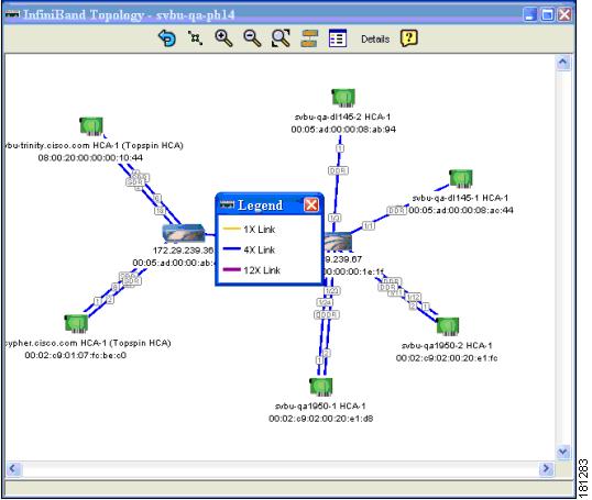
Figure 10-1 shows a sample topology view.
Figure 10-1 Topology View
Viewing Internal Server Switch Components and TCAs
To view the internal server switch components and target channel adapters (TCAs) inside a server switch, follow these steps:
Step 1 From the InfiniBand menu, choose Topology View.
The Specify Cisco Devices dialog box opens.
Step 2 (Optional) Check the check box in the Enabled column of any additional InfiniBand devices that you want to add to the Topology View display.
Step 3 Click OK.
The InfiniBand Topology window appears.
Step 4 Double-click a server switch icon.
The Internal InfiniBand Topology window opens.
Note Navigation icons appear at the top of the InfiniBand Topology window. Table 10-2 describes these icons.
Table 10-2 Internal InfiniBand Topology Navigation Icons
Icon
|
Description
|

|
The Layout icon evenly arranges the switch and HCA icons.
|

|
The Zoom In icon enlarges the display.
|

|
The Zoom Out icon condenses the display.
|

|
The Fit to Screen icon zooms in or out to fit the topology in the window.
|

|
The Layout icon evenly arranges the switch and HCA icons.
|

|
The Subnet Management Agents icon displays Subnet Manager agent details. For information, see the "Viewing Subnet Management Agents" section.
|

|
The Help icon launches the online help.
|
Viewing Subnet Details
These topics describe how to view subnet details:
•Viewing Nodes
•Viewing Ports
•Viewing Switches
•Viewing Neighboring Ports
Viewing Nodes
To view the nodes in the topology view, follow these steps:
Step 1 From the InfiniBand menu, choose Topology View.
The Specify Cisco Devices dialog box opens.
Step 2 (Optional) In the Enabled column, check the check box of any additional InfiniBand devices that you want to add to the Topology View display.
Step 3 Click OK.
The InfiniBand Topology window appears.
Step 4 Click Details.
The InfiniBand Subnet Details window opens.
Step 5 Click the Nodes tab.
Table 10-3 describes the fields in this tab.
Table 10-3 Nodes Tab Field Descriptions
Field
|
Description
|
SubnetPrefix
|
Subnet prefix of the node.
|
GUID
|
Global unique ID (GUID) of the node.
|
Description
|
Optional text string describing this node.
|
Type
|
Type of node being managed.
|
NumPorts
|
Number of physical ports on this node.
|
SystemImageGUID
|
System image GUID of this node. All nodes within a particular system (chassis) are assigned the same system image GUID.
|
Viewing Ports
To view the ports in the topology view, follow these steps:
Step 1 From the InfiniBand menu, choose Topology View.
The Specify Cisco Devices dialog box opens.
Step 2 (Optional) In the Enabled column, check the check box of any additional InfiniBand devices that you want to add to the Topology View display.
Step 3 Click OK.
The InfiniBand Topology window appears.
Step 4 Click Details.
The InfiniBand Subnet Details window opens.
Step 5 Click the Ports tab.
Table 10-4 describes the fields in this tab.
Step 6 Click Show Advanced to display additional port information. Table 10-4 describes the information.
Table 10-4 Ports Tab Field Descriptions
Field
|
Description
|
SubnetPrefix
|
Subnet prefix of the node.
|
NodeGUID
|
Global unique ID (GUID) of the node that includes the port.
|
Port
|
Local port number for this port.
|
LID
|
16-bit base LID of this port.
|
State
|
State of the port, as follows:
•noStateChange
•sleep
•polling
•disabled
•portConfigurationTraining
•linkup
•linkErrorRecovery
•reserved
•active
•down
|
LinkWidthActive
|
Active link width. Used in conjunction with LinkSpeedActive to determine the link rate between two nodes. The value appears as 1x, 4x, or 12x.
|
MKey
|
64-bit management key for this port. See section 14.2.4, "Management Key" and 3.5.3, "Keys," in InfiniBand Architecture®, Vol. 1, Release 1.1, for more information.
|
GID Prefix
|
64-bit Global identifier prefix for this port. The subnet manager assigns this prefix based upon the port routes and the rules for local identifiers. See section 4.1.3, "Local Identifiers," in InfiniBand Architecture®, Vol. 1, Release 1.1, for more information.
|
MasterSmLID
|
16-bit base LID of the master subnet manager managing this port.
|
CapMask
|
The capability mask identifies the functions that the host supports. 32-bit bitmask that specifies the supported capabilities of the port. A bit value of 1 (one) indicates a supported capability. The bits are 0, 11-15, 18, 21-31 (Reserved and always 0.), 1 IsSM, 2 IsNoticeSupported, 3 IsTrapSupported, 4 IsResetSupported, 5 IsAutomaticMigrationSupported, 6 IsSLMappingSupported, 7 IsMKeyNVRAM (supports M_Key in NVRAM), 8 IsPKeyNVRAM (supports P_Key in NVRAM), 9 Is LED Info Supported, 10 IsSMdisabled, 16 IsConnectionManagementSupported, 17 IsSNMPTunnelingSupported, 19 IsDeviceManagementSupported, 20 IsVendorClassSupported.Values are expressed in hexadecimal.
|
DiagCode
|
16-bit diagnostic code. See section 14.2.5.6.1 "Interpretation of Diagcode," in InfiniBand Architecture®, Vol. 1, Release 1.1, for more information. This field does not currently apply to your server switch.
|
MKeyLeasePeriod
|
Initial value of the lease-period timer, in seconds. The lease period is the length of time that the M_Key protection bits are to remain non-zero after a SubnSet (PortInfo) fails an M_Key check. After the lease period expires, clearing the M_Key protection bits allows any subnet manager to read (and then set) the M_Key. Set this field to 0 to indicate that the lease period never expires. See InfiniBand Architecture®, Vol. 1, Release 1.1, section 14.2.4, "Management Key."
|
LinkWidthEnabled
|
Enabled link width (bandwidth). The value (an integer) indicates the enabled link-width sets for this port. The value can be one of the following:
•no state change
•1x
•4x
•1x, 4x
•8x
•1x, 8x
•4x, 8x
•1x, 4x, 8x
•12x
•1x, 12x
•4x, 12x
•1x, 4x, 12x
•8x, 12x
•1x, 8x, 12x
•4x, 8x, 12x
•1x, 4x, 8x, 12x
•reserved
•linkwidthsupported value
|
LinkWidthSupported
|
Supported link width. The value appears as one of the following:
•1x,
•1x, 4x
•1x, 4x, 8x
•1x, 4x, 12x,
•1x, 4x, 8x, 12x
•reserved
|
LinkSpeedSupported
|
Supported link speed. The value appears as one of the following:
•sdr
•sdr, ddr
|
PhyState
|
Indicates the physical state of the port, whether or not electricity flows between nodes and that they can perform a handshake. The value appears as noStateChange, sleeping, polling, disabled, portConfigurationTraining, linkup, or linkErrorRecovery. The state, upon power-up, defaults to polling.
|
LinkDownDefState
|
Default LinkDown state to return to. The value appears as noStateChange, sleeping, or polling. See section 5.5.2, "Status Outputs (MAD GET)," InfiniBand Architecture®, Vol. 1, Release 1.1, for more information.
|
MKeyProtBits
|
Management key protection bits for the port. The bits are 0, 1, 2, and 3. See section 14.2.4.1, "Levels of Protection," InfiniBand Architecture®, Vol. 1, Release 1.1, for more information.
|
LMC
|
Local-identifier mask control (LMC) for multi-path support. A LMC resides on each channel adapter and router port on the subnet. It provides multiple virtual ports within a single physical port. The value of the LMC specifies the number of path bits in the LID. A value of 0 (zero) indicates one LID can apply to this port. See sections 3.5.10, "Addressing," and 4.1.3, "Local Identifiers," InfiniBand Architecture®, Vol. 1, Release 1.1, for more information.
|
LinkSpeedActive
|
Speed of an active link. The value appears as one of the following:
•sdr
•ddr
|
LinkSpeedEnabled
|
Maximum speed that the link can handle. The value appears as one of the following:
•sdr
•ddr
•sdr, ddr
|
NeighborMTU
|
Active maximum transmission unit enabled on this port for transmit. Check the MTUCap value at both ends of every link and use the lesser speed. The value appears as 256, 512, 1024, 2048, or 4096.
|
MasterSmSL
|
Administrative service level required for this port to send a non-SMP message to the subnet manager.
|
VLCap
|
Maximum range of data virtual lanes supported by this port. The value appears as vl0, vl0-Vl1, vl0-Vl3, vl0-Vl7, or vl0-Vl14. See also oper-VL. Each port can support up to 15 virtual lanes (VLs 0 - 15). The VL-cap field displays the range of those lanes (for example, lanes 0 - 7) that the port currently supports.
|
VLHighLimit
|
Maximum high-priority limit on the number of bytes allowed for transmitting high-priority packets when both ends of a link operate with multiple data virtual-lanes. Used with the virtual-lane arbitration table. The maximum high-limit matches the VLArbHighSap on the other side of the link and then negotiating downward.
|
VLArbHighCap
|
Highest arbitration value allowed by the arbiter in determining the next packet in a set of packets to send across the link. Used with the virtual-lane arbitration table and specified as a VL/Weight pair. See section 14.2.5.9, "VL Arbitration Table," InfiniBand Architecture®, Vol. 1, Release 1.1, for more information.
|
VLArbLowCap
|
Lowest arbitration value allowed by the arbiter in determining the next packet in a set of packets to send across the link. Used with the virtual-lane arbitration table and specified as a VL/Weight pair. See section 14.2.5.9, "VL Arbitration Table," InfiniBand Architecture®, Vol. 1, Release 1.1, for more information.
|
MTUCap
|
Used in conjunction with NeighborMTU to determine the maximum transmission size supported on this port. The lesser of MTUCap and NeighborMTU determines the actual MTU used. The value appears as 256, 512, 1024, 2048, or 4096.
|
VLStallCount
|
Number of sequentially dropped packets at which the port enters a VLStalled state. The virtual lane exits the VLStalled state (8 * HLL) units after entering it. See section 18.2.5.4, "Transmitter Queuing," InfiniBand Architecture®, Vol. 1, Release 1.1, for a description of HLL.
|
HOQLife
|
Maximum duration allowed to packets at the head of a virtual-lane queue. Used with VLStallCount to determine the outgoing packets to discard.
|
OperVL
|
Administrative limit for the number of virtual lanes allowed to the link. Do not set this above the VLCap value. The value appears as vl0, vl0-Vl1, vl0-Vl3, vl0-Vl7, or vl0-Vl14.
|
InPartEnforce
|
Boolean value that indicates whether or not to support optional partition enforcement for the packets that were received by this port. No default value applies.
|
OutPartEnforce
|
Boolean value that indicates whether or not to support optional partition enforcement for the packets transmitted by this port. No default value applies.
|
InFilterRawPktEnforce
|
Boolean value that indicates whether or not to support optional raw packet enforcement for the raw packets that were received by this port. No default value applies.
|
OutFilterRawPktEnforce
|
Boolean value that indicates whether or not to support optional raw packet enforcement for the raw packets transmitted by this port. No default value applies.
|
MKeyViolation
|
Number of subnet management packets (SMPs) that have been received on this port with invalid M_Keys since initial power up or the last reset. See section 14.2.4, "Management Key," InfiniBand Architecture®, Vol. 1, Release 1.1, for more information.
|
PKeyViolation
|
Number of subnet management packets that have been received on this port with invalid P_Keys since initial power up or the last reset. See section 9.2.7, "Partition Key (P_KEY)," InfiniBand Architecture®, Vol. 1, Release 1.1, for more information.
|
QKeyViolation
|
Number of subnet management packets that have been received on this port with invalid Q_Keys since initial power up or the last reset. See section 10.2.4, "Q Keys," InfiniBand Architecture®, Vol. 1, Release 1.1, for more information.
|
GUIDCap
|
Number of GUID entries allowed for this port in the port table. Any entries that exceed this value are ignored on write and read back as zero. See section 14.2.5.5, "GUIDCap," InfiniBand Architecture®, Vol. 1, Release 1.1, for more information.
|
SubnetTimeout
|
Maximum propagation delay allowed for this port to reach any other port in the subnet. This value also affects the maximum rate at with traps can be sent from this port. Switch configuration affects delay. Requestors can use this parameter to determine the interval to wait for a response to a request. Duration matches (4.096 ms * 2^SubnetTimeout).
|
RespTime
|
Maximum time allowed between the port reception of a subnet management packet and the transmission of the associated response. See section 13.4.6.2, "Timers and Timeouts," InfiniBand Architecture®, Vol. 1, Release 1.1, for more information.
|
LocalPhyError
|
Threshold at which ICRC, VCRC, FCCRC, and all physical errors result in an entry into the BAD PACKET or BAD PACKET DISCARD states of the local packet receiver. See section 7.12.2, "Error Recovery Procedures," InfiniBand Architecture®, Vol. 1, Release 1.1, for more information.
|
LocalOverrunError
|
Threshold at which the count of buffer overruns, across consecutive flow-control update periods, result in an overrun error. A possible cause of such errors is when an earlier packet has physical errors and the buffers are not immediately reclaimed.
|
Viewing Switches
To view the switches in the topology view, follow these steps:
Step 1 From the InfiniBand menu, choose Topology View.
The Specify Cisco Devices dialog box opens.
Step 2 (Optional) Check the check box in the Enabled column of additional InfiniBand devices to add to the Topology View display.
Step 3 Click OK.
The InfiniBand Topology window appears.
Step 4 Click Details.
The InfiniBand Subnet Details window opens.
Step 5 Click the Switches tab.
Table 10-5 describes the fields in this tab.
Table 10-5 Switches Tab Field Descriptions
Field
|
Description
|
SubnetPrefix
|
Subnet prefix of the node.
|
NodeGUID
|
Global unique ID (GUID) of the node that includes the switch.
|
LinearFdbCap
|
Number of entries supported in the Linear Unicast Forwarding table. Zero indicates that there is no Linear Forwarding Database.
|
RandomFdbCap
|
Number of entries supported in the Random Unicast Forwarding table. Zero indicates that there is no Random Forwarding Database.
|
McastFdbCap
|
Number of entries supported in the Multicast Forwarding table.
|
LinearFdbTop
|
Indicates the top of the linear forwarding table. Packets received with unicast DLIDs greater than this value are discarded by the switch. This component applies only to switches that implement linear forwarding tables and is ignored by switches that implement random forwarding tables.
|
DefaultPort
|
Forward to this port all the unicast packets from the other ports where DLID does not exist in the random forwarding table.
|
DefPriMcastPort
|
Forward to this port all the multicast packets from the other ports where DLID does not exist in the forwarding table.
|
DefNonPriMcastPort
|
Forward to this port all the multicast packets from the smDefPriMcastPort port where DLID does not exist in the forwarding table.
|
LifeTimeValue
|
Time a packet can live in the switch.
|
PortStateChange
|
Identifies whether or not the port is in transition.
|
LIDPerPort
|
Number of LID/LMC combinations that may be assigned to a given external port for switches that support the random forwarding table.
|
PartitionEnfCap
|
Number of entries in this partition enforcement table per physical port. Zero indicates that partition enforcement is not supported by the switch.
|
InEnfCap
|
Indicates switch is capable of partition enforcement on received packets.
|
OutEnfCap
|
Indicates switch is capable of partition enforcement on transmitted packets.
|
InFilterRawPktCap
|
Indicates switch is capable of raw packet enforcement on received packets.
|
OutFilterRawPktCap
|
Indicates switch is capable of raw packet enforcement on transmitted packets.
|
Viewing Neighboring Ports
To view neighboring ports in the topology view, follow these steps:
Step 1 From the InfiniBand menu, choose Topology View.
The Specify Cisco Devices dialog box opens.
Step 2 (Optional) Check the check box in the Enabled column of any additional InfiniBand devices that you want to add to the Topology View display.
Step 3 Click OK.
The InfiniBand Topology window appears.
Step 4 Click Details.
The InfiniBand Subnet Details window opens.
Step 5 Click the Neighbors tab.
Table 10-6 describes the fields in this tab.
Table 10-6 Neighbors Tab Field Descriptions
Field
|
Description
|
SubnetPrefix
|
Used to identify InfiniBand subnet in which this InfiniBand node is located.
|
LocalNodeGuid
|
Global unique ID (GUID) of the InfiniBand node.
|
LocalPortId
|
Port ID of the InfiniBand node.
|
LocalNodeType
|
Identifies the node type of the InfiniBand node as follows.
•channelAdapter
•switch
|
RemoteNodeGuid
|
Global unique ID (GUID) of the remote InfiniBand node.
|
RemotePortId
|
Port ID of the remote InfiniBand node.
|
RemoteNodeType
|
Identifies the remote InfiniBand node's node-type, as follows:
•channelAdapter
•switch
|
LinkState
|
Identifies the state of the link connecting the neighbors, as follows:
•noStateChange
•down
•initialize
•active
|
LinkWidthActive
|
Width of the link connecting the neighbors.
|
Viewing Subnet Management Agents
These topics describe how to view Subnet Manager Agent details:
•Viewing Subnet Manager Node Details
•Viewing Subnet Manager Switch Details
•Viewing Subnet Manager Agent Switch Cap Details
•Viewing Subnet Manager Agent Ports(1) Details
•Viewing Subnet Manager Agent Ports (2) Details
•Viewing Subnet Manager Multicast Details
•Viewing Subnet Manager Agent Linear Forwarding Table Details
•Viewing the Subnet Manager Agent Partition Details
•Viewing the Subnet Manager Agent SLVL Map
Viewing Subnet Manager Node Details
To view Subnet Manager Agent node details, follow these steps:
Step 1 From the InfiniBand menu, choose Topology View.
The Specify Cisco Devices dialog box opens.
Step 2 (Optional) Check the check box in the Enabled column for any additional InfiniBand devices that you want to add to the Topology View display.
Step 3 Click OK.
The InfiniBand Topology window appears.
Step 4 Double-click a server switch icon.
Step 5 The Internal InfiniBand Topology window opens.
Step 6 Click SMAs.
The Subnet Manager Agents window opens.
Step 7 Click the Nodes tab.
Table 10-7 describes the fields in this tab.
Table 10-7 Nodes Tab Field Descriptions
Field
|
Description
|
Guid
|
Subnet prefix of this InfiniBand subnet.
|
BaseVersion
|
Supported base management datagram version.
|
ClassVersion
|
Supported subnet management class.
|
Type
|
Type of node being managed: channelAdapter or switch
|
PortGuid
|
GUID of this port. One port within a node can return the nodeGUID as its PortGUID if the port is an integral part of the node and is not field-replaceable.
|
PartitionCap
|
Number of entries in the partition table for CA, router, and the switch management port. This is at a minimum set to 1 for all nodes including switch.
|
DeviceId
|
Device ID information as assigned by the device manufacturer.
|
Revision
|
Device revision assigned by manufacturer.
|
LocalPortNum
|
The link port number that this SNMP packet came in on.
|
VendorId
|
Device vendor ID, per IEEE.
|
TrapBuffer
|
Special-purpose string buffer for InfiniBand Trap Data.
|
String
|
Description of the node.
|
NumPorts
|
Number of physical ports on this node.
|
Viewing Subnet Manager Switch Details
To view Subnet Manager Agent switch details, follow these steps:
Step 1 From the InfiniBand menu, choose Topology View.
The Specify Cisco Devices dialog box opens.
Step 2 (Optional) Check the check box in the Enabled column for any additional InfiniBand devices that you want to add to the Topology View display.
Step 3 Click OK.
The InfiniBand Topology window appears.
Step 4 Double-click a server switch icon.
The Internal InfiniBand Topology window opens.
Step 5 Click SMAs.
Step 6 The Subnet Manager Agents window opens.
Step 7 Click the Switches tab.
Table 10-8 describes the fields in this tab.
Table 10-8 Switches Tab Field Descriptions
Field
|
Description
|
Guid
|
Global unique ID of the switch.
|
LftTop
|
Top of the linear forwarding table. Packets received with unicast DLids greater than this value are discarded by the switch. This component applies only to switches that implement linear forwarding tables and is ignored by switches that implement random forwarding tables.
|
DefaultPort
|
Forward to this port all the unicast packets from the other ports where DLID does not exist in the random forwarding table.
|
DefMcastPriPort
|
Forward to this port all the multicast packets from the other ports where DLID does not exist in the forwarding table.
|
DefMcastNPPort
|
Forward to this port all the multicast packets from the Default Primary port where DLID does not exist in the forwarding table.
|
LifeTimeValue
|
Time that a packet can live in the switch.
|
PortStateChange
|
Set to one when the PortState component in the PortInfo of any ports transitions from Down to Initialize, Initialize to Down, Armed to Down, or Active to Down as a result of link state machine logic. Changes in Portstate resulting from SubnSet do not change this bit. This bit is cleared by writing one; writing zero is ignored.
|
LidsPerPort
|
Number of LID/LMC combinations that may be assigned to a given external port for switches that support the random forwarding table.
|
Viewing Subnet Manager Agent Switch Cap Details
To view Subnet Manager Agent switch cap details, follow these steps:
Step 1 From the InfiniBand menu, choose Topology View.
The Specify Cisco Devices dialog box opens.
Step 2 (Optional) Check the check box in the Enabled column for any additional InfiniBand devices that you want to add to the Topology View display.
Step 3 Click OK.
The InfiniBand Topology window appears.
Step 4 Double-click a server switch icon.
The Internal InfiniBand Topology window opens.
Step 5 Click SMAs.
The Subnet Manager Agents window opens.
Step 6 Click the Switch Cap tab.
Table 10-9 describes the fields in this tab.
Table 10-9 Switch Cap Tab Field Descriptions
Field
|
Description
|
LftCap
|
Number of entries supported in the linear unicast forwarding table.
|
RftCap
|
Number of entries supported in the random unicast forwarding table. RandomFDBCap = 0 indicates that there is no random forwarding database.
|
MftCap
|
Number of entries supported in the multicast forwarding table.
|
PartitionEnfCap
|
Number of entries in the partition enforcement table per physical port. Zero indicates that partition enforcement is not supported by the switch.
|
InboundEnfCap
|
Indicates switch is capable of partition enforcement on received packets.
|
OutboundEnfCap
|
Indicates switch is capable of partition enforcement on transmitted packets.
|
FilterRawPktInCap
|
Indicates switch is capable of raw packet enforcement on received packets.
|
FilterRawPktOutCap
|
Indicates switch is capable of raw enforcement on transmitted packets.
|
Viewing Subnet Manager Agent Ports(1) Details
To view Subnet Manager Agent port details, follow these steps:
Step 1 From the InfiniBand menu, choose Topology View.
The Specify Cisco Devices dialog box opens.
Step 2 (Optional) Check the check box in the Enabled column of any additional InfiniBand devices that you want to add to the Topology View display.
Step 3 Click OK.
The InfiniBand Topology window appears.
Step 4 Double-click a server switch icon.
The Internal InfiniBand Topology window opens.
Step 5 Click SMAs.
The Subnet Manager Agents window opens.
Step 6 Click the Ports (1) tab.
Table 10-10 describes the fields under this tab.
Table 10-10 Ports (1) Tab Field Descriptions
Field
|
Description
|
NodeGuid
|
64-bit GUID of the node that contains this port.
|
IbPort
|
Local port number of this port (relative to a particular node).
|
MKey
|
64-bit management key for this port.
|
GidPrefix
|
64-bit global ID prefix for this port.
|
Lid
|
16-bit base LID of this port.
|
MasterSMLid
|
16-bit base LID of the master Subnet Manager that is managing this port.
|
CapabilityMask
|
Supported capabilities of this node are as follows:
•0: Reserved, shall be zero
•1: IsSM
•2: IsNoticeSupported
•3: IsTrapSupported
•4: IsResetSupported
•5: IsAutomaticMigrationSupported
•6: IsSLMappingSupported
•7: IsMKeyNVRAM
•8: IsPKeyNVRAM
•9: IsLEDInfoSupported
•10: IsSMDisabled
•11-15: Reserved, shall be zero
•16: IsConnectionManagerSupported
•17: IsSNMPTunnelingSupported
•18: Reserved, shall be zero
•19: IsDeviceManagementSupported
•20: IsVendorClassSupported
•21-31: Reserved, shall be zero
|
DiagCode
|
Port diagnostic code.
|
MKeyLeasePeriod
|
Timer value used to indicate how long the M_Key protection bits are to remain nonzero after a SubnSet(PortInfo) fails an M Key check. The value of the timer indicates the number of seconds for the lease period.
|
LocalPortNum
|
Local port number.
|
LinkWidthEnabled
|
Enabled link width (1x, 4x, or 12x).
|
LinkWidthSupported
|
Supported link width.
|
LinkWidthActive
|
Currently active link width.
|
LinkSpeedSupported
|
Supported link speed (in Gbps).
|
State
|
State of the port is as follows:
•noStateChagne
•down
•initialize
•armed
•active
|
PortPhys
|
State of the physical port is as follows:
•noStateChange(0),
•sleep
•polling
•disabled
•portConfigurationTraining
•linkup
•linkErrorRecovery
•reserved
•linkDownDef
|
LinkDownDef
|
Port physical state link down.
|
MKeyProtectBits
|
Determines MADheader behavior.
|
LMC
|
LID mask for multipath support.
|
LSActive
|
Current active link speed.
|
LSActiveEnabled
|
Enabled link speed.
|
NeighborMTU
|
Active maximum MTU enabled on this port for transmission.
|
MasterSMSL
|
Administrative SL of the master Subnet Manager that is managing this port.
|
Viewing Subnet Manager Agent Ports (2) Details
To view extended Subnet Manager Agent port details, follow these steps:
Step 1 From the InfiniBand menu, choose Topology View.
The Specify Cisco Devices dialog box opens.
Step 2 (Optional) Check the check box in the Enabled column for any additional InfiniBand devices that you want to add to the Topology View display.
Step 3 Click OK.
The InfiniBand Topology window appears.
Step 4 Double-click a server switch icon.
The Internal InfiniBand Topology window opens.
Step 5 Click SMAs.
The Subnet Manager Agents window opens.
Step 6 Click the Ports (2) tab.
Table 10-11 describes the fields in this tab.
Table 10-11 Ports (2) Tab Field Descriptions
Field
|
Description
|
NodeGuid
|
64-bit GUID of the node that contains this port.
|
IbPort
|
Local port number of this port (relative to a particular node).
|
VLCap
|
Virtual lanes supported on this port.
|
VLHighLimit
|
Limit of high priority component of VL arbitration table.
|
VLArbitrationHighCap
|
VL/Weight pairs supported on this port in the smVLArbTable for high priority.
|
VLArbitrationLowCap
|
VL/Weight pairs supported on this port in the smVLArbTable for low priority.
|
MTUCap
|
Maximum MTU supported by this port.
|
VLStallCount
|
Number of sequential packets dropped that caused the port to enter the VLStalled state.
|
HoQLife
|
Time that a packet can live at the head of a VL queue.
|
OpVLs
|
Virtual Lanes operational on this port.
|
PkeyEnfIn
|
Indicates support of optional partition enforcement on packets received from this port.
|
PkeyEnfOut
|
Indicates support of optional partition enforcement on packets transmitted from this port.
|
FilterRawPktIn
|
Indicates support of optional raw packet enforcement on raw packets received from this port.
|
FilterRawPktOut
|
Indicates support of optional raw packet enforcement on raw packets transmitted from this port.
|
MKeyViolations
|
Number of SMP packets that were received on the port and had an invalid M_Key, since power on or reset.
|
PKeyViolations
|
Number of packets that were received on the port and had an invalid P_Key, since power on or reset.
|
QKeyViolations
|
Number of packets that have been received on the port that have had an invalid Q_Key, since power on or reset
|
GuidCap
|
Number of GUID entries supported in the GUIDInfo attribute for this port.
|
SubnetTimeout
|
Maximum expected subnet propagation delay.
|
RespTimeValue
|
Expected maximum time between the port reception of an SMP and the transmission of the associated response.
|
LocalPhysErr
|
Threshold value. When the count of marginal link errors exceeds this threshold, the local link integrity error is detected.
|
OverrunErr
|
Overrun threshold value. When the count of buffer overruns exceeds the threshold, an excessive buffer overrun error occurs.
|
Viewing Subnet Manager Multicast Details
To view Subnet Manager Agent multicast details, follow these steps:
Step 1 From the InfiniBand menu, choose Topology View.
The Specify Cisco Devices dialog box opens.
Step 2 (Optional) Check the check box in the Enabled column for any additional InfiniBand devices that you want to add to the Topology View display.
Step 3 Click OK.
The InfiniBand Topology window appears.
Step 4 Double-click a server switch icon.
The Internal InfiniBand Topology window opens.
Step 5 Click SMAs.
The Subnet Manager Agents window opens.
Step 6 Click the Mcast tab.
Table 10-12 describes the fields in this tab.
Table 10-12 Mcast Tab Field Descriptions
Field
|
Description
|
NodeGuid
|
Global unique ID of the node.
|
TableBlockIndex
|
Index into the multicast block table: this index starts from 1 rather than 0.
|
TableBlock
|
List of 32 PortMask Block Elements. 16 bits starting at position 16*p of the port mask are associated with the particular LID. An incoming packet with this LID is forwarded to all ports for which the bit in the port mask is set to 1. An invalid LID is indicated with an all zero PortMask.
|
Viewing Subnet Manager Agent Linear Forwarding Table Details
To view Subnet Manager Agent linear forwarding table details, follow these steps:
Step 1 From the InfiniBand menu, choose Topology View.
The Specify Cisco Devices dialog box opens.
Step 2 (Optional) Check the check box in the Enabled column for any additional InfiniBand devices that you want to add to the Topology View display.
Step 3 Click OK.
The InfiniBand Topology window appears.
Step 4 Double-click a server switch icon.
The Internal InfiniBand Topology window opens.
Step 5 Click SMAs.
The Subnet Manager Agents window opens.
Step 6 Click the Linear Forwarding tab.
Table 10-13 describes the fields in this tab.
Table 10-13 Linear Forwarding Tab Field Descriptions
Field
|
Description
|
NodeGuid
|
Global unique ID of the node.
|
BlockIndex
|
Index into the linear forwarding table; this index starts from 1 rather than 0.
|
Block
|
Linear forwarding table block.
|
Viewing the Subnet Manager Agent Partition Details
To view Subnet Manager Agent partition details, follow these steps:
Step 1 From the InfiniBand menu, choose Topology View.
The Specify Cisco Devices dialog box opens.
Step 2 (Optional) Check the check box in the Enabled column for any additional InfiniBand devices that you want to add to the Topology View display.
Step 3 Click OK.
The InfiniBand Topology window appears.
Step 4 Double-click a server switch icon.
The Internal InfiniBand Topology window opens.
Step 5 Click SMAs.
The Subnet Manager Agents window opens.
Step 6 Click the PKey tab.
Table 10-14 describes the fields in this tab.
Table 10-14 PKey Tab Field Descriptions
Field
|
Description
|
NodeGuid
|
Global unique ID of the node.
|
IbPort
|
Port number.
|
Index
|
PKEY table index.
|
TableVector
|
GUID assigned by the Subnet Manager on the subnet.
|
Viewing the Subnet Manager Agent SLVL Map
To view Subnet Manager Agent SLVL details, follow these steps:
Step 1 From the InfiniBand menu, choose Topology View.
The Specify Cisco Devices dialog box opens.
Step 2 (Optional) Check the check box in the Enabled column for any additional InfiniBand devices that you want to add to the Topology View display.
Step 3 Click OK.
The InfiniBand Topology window appears.
Step 4 Double-click a server switch icon.
The Internal InfiniBand Topology window opens.
Step 5 Click SMAs.
The Subnet Manager Agents window opens.
Step 6 Click the SLVL Map tab.
Table 10-15 describes the fields in this tab.
Table 10-15 SLVL Map Tab Field Descriptions
Field
|
Description
|
NodeGuid
|
Global unique ID of the node.
|
InIbPort
|
Ingress port number.
|
OutIbPort
|
Egress port number.
|
Sl#toVI
|
SL# to VL mapping.
|

 Feedback