Feedback
Table Of Contents
Maintenance and Upgrade Procedures
Removing and Replacing the Chassis Cover
Removing and Replacing a Lithium Battery in the SSM
Removing and Replacing the Power Supply
Removing and Replacing the CompactFlash
Removing and Installing the System CompactFlash
Removing and Installing the User CompactFlash
Installing and Replacing the 4GE SSM
Installing and Removing the SFP Modules
Installing and Replacing the Intelligent SSM
Installing and Replacing the AIP/CSC SSM
Upgrading Memory in the Adaptive Security Appliance
Removing and Installing the DIMM
Maintenance and Upgrade Procedures
This chapter describes how to, remove and replace the chassis cover, the power supply, and the CompactFlash. This chapter includes the following sections:
•
Removing and Replacing the Chassis Cover
•
•
•
•
•
•
•
Removing and Replacing the Chassis Cover
This section describes how to remove and replace the chassis cover. This section includes the following topics:
Removing the Chassis Cover
To remove the chassis cover, perform the following steps:
Note
Step 1
Step 2
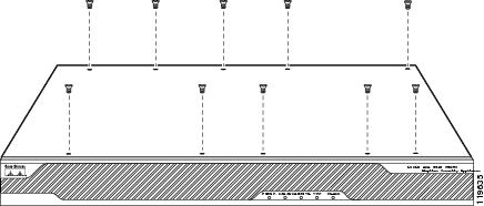
WarningStep 3
Figure 4-1 Removing the Top Panel Screws
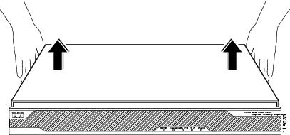
Step 4
Figure 4-2 Removing the Chassis Cover
Replacing the Chassis Cover
Caution
To replace the chassis cover, perform the following steps:
Step 1
Step 2
Step 3
Figure 4-3 Replacing the Chassis Cover
Step 4
Figure 4-4 Replacing the Screws
Step 5
Step 6
Working in an ESD Environment
Electrostatic discharge (ESD) can damage equipment and impair electrical circuitry. ESD damage occurs when electronic components are improperly handled and can result in complete or intermittent failures. Always follow ESD-prevention procedures when you remove and replace components. Ensure that the chassis is electrically connected to earth ground. Wear an ESD-preventive wrist strap, ensuring that it makes good skin contact. Connect the grounding clip to an unpainted surface of the chassis frame to safely ground unwanted ESD voltages. To guard against ESD damage and shocks, the wrist strap and cord must operate properly. If no wrist strap is available, ground yourself by touching the metal part of the chassis.
Removing and Replacing a Lithium Battery in the SSM
To remove and replace the battery in the SSM, perform the following steps:
Step 1
Step 2
Step 3
Step 4
Step 5
Removing and Replacing the Power Supply
For information on power supply considerations including environmental operating ranges and power requirements, see table 7 at the following url:
For information on AC-input power cord options, see Table 2-1in the "Power Supply Considerations" section
This section describes how to remove and replace the power supply, and includes the following topics:
•
Removing the AC Power Supply
To remove the AC power supply, perform the following steps:
Step 1
Step 2
Step 3
Step 4
Step 5
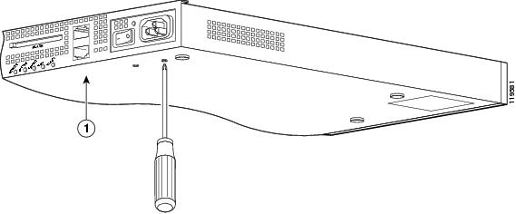
Step 6
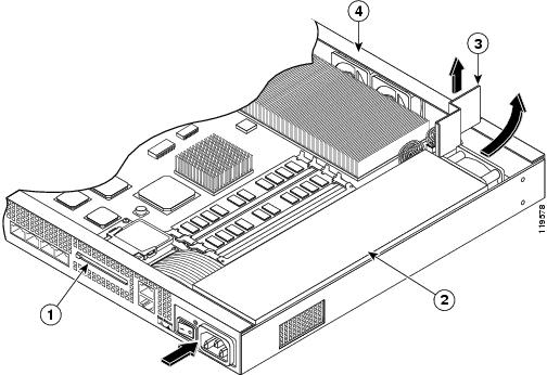
Figure 4-5 Removing the Power Supply Screws
Step 7
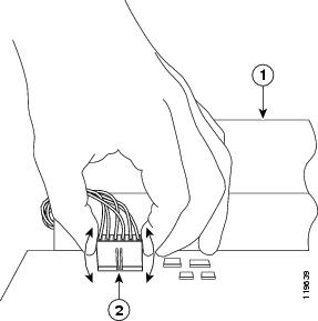
Step 8
Figure 4-6 Disconnecting the Power Connector
Step 9
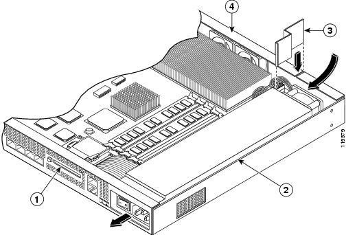
Figure 4-7 Removing the Power Supply
Step 10
Replacing the AC Power Supply
To replace the AC power supply, perform the following steps:
Step 1
Step 2
Step 3
Figure 4-8 Replacing the Power Supply Brace and the AC Power Supply
Step 4
Step 5
Step 6
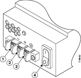
Installing the DC Model
Note
To install the DC power model, perform the following steps:
Step 1
Step 2
Step 3
Figure 4-9 DC-Input Terminal Box
Step 4
Step 5
Step 6
Step 7
Step 8
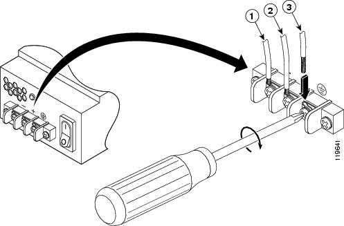
Note
Figure 4-10 DC-Input Power Supply Connections
Step 9
Step 10
Step 11
Step 12
Note
Removing and Replacing the CompactFlash
The adaptive security appliance has two types of CompactFlash: the system CompactFlash (internal) and the user CompactFlash (external). This section includes the following topics:
•
•
Removing and Installing the System CompactFlash
To remove and install the system CompactFlash, perform the following steps:
Step 1
Step 2
Step 3
Step 4
Step 5
Step 6
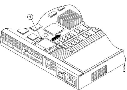
Figure 4-11 Removing the System CompactFlash
Step 7
Step 8
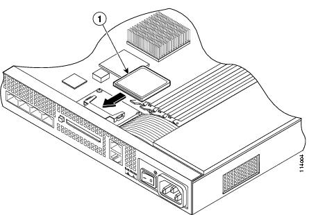
Figure 4-12 Replacing the System CompactFlash
Step 9
Step 10
Removing and Installing the User CompactFlash
To remove and install the user CompactFlash, perform the following steps:
Note
Step 1
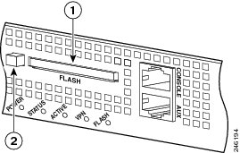
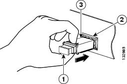
Figure 4-13 User CompactFlash and Release Button Location—Type A and B
Step 2
In Type B pressing the release button once will eject the CompactFlash, the release button will be slightly extended. See Figure 4-15. If this is the case, skip Step 3 and go to Step 4.
Figure 4-14 Release Button Fully Extended—Type A
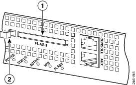
Figure 4-15 User CompactFlash and Release Button Slightly Extended—Type B
Step 3
Figure 4-16 User CompactFlash and Release Button Extended—Type A
Step 4
Note
Step 5
Step 6
The release button will remain extended when you insert the CompactFlash see Figure 4-13.
Installing and Replacing the 4GE SSM
The 4GE SSM has four 10/100/1000 Mbps, copper, RJ-45 ports and four optional 1000 Mbps, Small-Form-Factor Pluggable (SFP) fiber ports.
Note
This section describes how to install and replace the 4GE SSM in the adaptive security appliance, and includes the following topics:
•
Overview
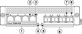
Figure 4-17 lists the 4GE SSM ports and LEDs.
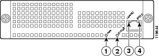
Figure 4-17 4GE SSM Ports and LEDs
RJ-45 ports
Status LED
RJ-45 Link LED
SFP ports
RJ-45 Speed LED
SFP Link LED
Power LED
SFP Speed LED
Note
Table 4-1 describes the 4GE SSM LEDs.
Installing the 4GE SSM
To install a new 4GE SSM for the first time, perform the following steps:
Step 1
Step 2
Step 3
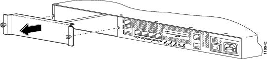
Figure 4-18 Removing the Screws from the Slot Cover
Step 4
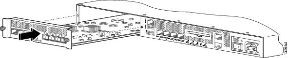
Figure 4-19 Inserting the 4GE SSM into the Slot
Step 5
Step 6
Step 7
Step 8
Replacing the 4GE SSM
To replace an existing 4GE SSM, perform the following steps:
Step 1
Step 2
Step 3
Step 4
Step 5
Step 6
Step 7
Step 8
Step 9
Installing and Removing the SFP Modules
The SFP is a hot-swappable input/output device that plugs into the SFP ports. The following SFP module types are supported:
•
•
This section describes how to install and remove the SFP modules in the adaptive security appliance to provide optical Gigabit Ethernet connectivity. It contains the following topics:
SFP Module
The adaptive security appliance uses a field-replaceable SFP module to establish Gigabit connections.
Table 4-2 lists the SFP modules that are supported by the adaptive security appliance.
Table 4-2 Supported SFP Modules
1000BASE-LX/LH
Fiber-optic
GLC-LH-SM=
1000BASE-SX
Fiber-optic
GLC-SX-MM=
The 1000BASE-LX/LH and 1000BASE-SX SFP modules are used to establish fiber-optic connections. Use fiber-optic cables with LC connectors to connect to an SFP module. The SFP modules support 850 to 1550 nm nominal wavelengths. The cables must not exceed the required cable length for reliable communications. Table 4-3 lists the cable length requirements.
Use only Cisco certified SFP modules on the adaptive security appliance. Each SFP module has an internal serial EEPROM that is encoded with security information. This encoding provides a way for Cisco to identify and validate that the SFP module meets the requirements for the adaptive security appliance.
Note
Caution
WarningInstalling the SFP Module
To install the SFP module in the 4GE SSM, perform the following steps:
Step 1
Figure 4-20 Installing an SFP Module
Caution
Step 2
Step 3
Caution
Removing the SFP Module
The SFP modules have different types of latching devices used to detach the SFP module from a port. The following are the different types of modules:
•
•
•
•
To remove the SFP module, perform the following steps:
Step 1
Warning
Caution
Step 2
Note
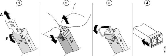
Figure 4-21 Disconnecting SFP Latch Mechanisms
Step 3
Installing and Replacing the Intelligent SSM
The Cisco ASA 5510, Cisco ASA 5520, Cisco ASA 5540 support the AIP SSM and the CSC SSM, also referred to as the intelligent SSM in this document.The AIP SSM runs advanced IPS software that provides security inspection. There are three types of AIP SSM: the AIP SSM 10, AIP SSM 20 and the AIP SSM 40. The AIP SSM 10 and the AIP SSM 20 look identical, but the AIP SSM 20 has a faster processor and more memory than the AIP SSM 10. The AIP SSM 40 has a faster processor and more memory than both the AIP SSM 10 and the AIP SSM 20. Only one module (the AIP SSM 10, AIP SSM 20, or the AIP SSM 40) can populate the slot at a time.
Table 4-4 lists the memory specifications for the AIP SSM 10, AIP SSM 20, and the AIP SSM 40.
Table 4-4 AIP/CSC SSM Memory Specifications
AIP SSM 10
2.0 GHz Celeron
1.0 GB
AIP SSM 20
2.4 GHz Pentium 4
2.0 GB
AIP SSM 40
2.0 GHz Xeon LV
4.0 GB
For more information on the AIP SSM 10/20/40, see the "Managing the AIP SSM" section in the Cisco Security Appliance Command Line Configuration Guide.
The CSC SSM runs Content Security and Control software. The CSC SSM provides protection against viruses, spyware, spam, and other unwanted traffic. There are two types of CSC SSM: the CSC SSM 10, and the CSC SSM 20. For more information on the CSC SSM 10/20, see the "Managing the CSC SSM" section in the Cisco Security Appliance Command Line Configuration Guide.
Table 4-5 shows the AIP/CSC SSMs supported by each platform:
This section describes how to install and replace the AIP/CSC SSM in the adaptive security appliance, and includes the following topics:
•
Overview
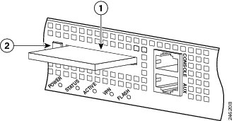
Figure 4-22 lists the AIP/CSC SSM 10/20 LEDs.
Figure 4-22 AIP/CSC SSM 10/20 LEDs
Table 4-6 describes the AIP/CSC SSM 10/20 LEDs.
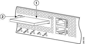
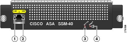
Figure 4-23 lists the AIP/CSC SSM 40 LEDs.
Figure 4-23 AIP/CSC SSM 40 LEDs
Table 4-6 describes the AIP/CSC SSM 10/20 LEDs.
Installing and Replacing the AIP/CSC SSM
This section describes how to install and replace the AIP/CSC SSM in the adaptive security appliance. The section includes the following topics:
Installing the AIP/CSC SSM
To install a new AIP/CSC SSM for the first time, perform the following steps:
Step 1
Step 2
Step 3
Figure 4-24 Removing the Screws from the Slot Cover
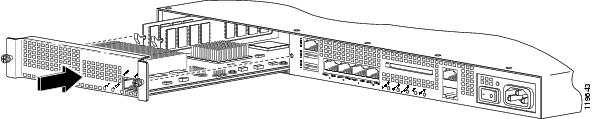
Step 4
Figure 4-25 Inserting the AIP/CSC SSM into the Slot
Step 5
Step 6
Step 7
Replacing the AIP/CSC SSM
To replace an existing AIP/CSC SSM, perform the following steps:
Step 1
Step 2
Step 3
Step 4
Step 5
Step 6
Step 7
Step 8
Upgrading Memory in the Adaptive Security Appliance
This section describes how to upgrade the memory in the adaptive security appliance. The section includes the following topics:
•
Overview
Cisco ASA 5510
The memory upgrade kit, ASA5510-MEM-512=, allows you to upgrade the memory in your Cisco ASA 5510.
To determine how much memory your adaptive security appliance has, use the show version command, the example below is for the Cisco ASA 5510 chassis:
hostname# show versionCisco Adaptive Security Appliance Software Version 8.0(4)Device Manager Version 6.1(5)Compiled on Thu 07-Aug-08 20:53 by buildersSystem image file is "disk0:/asa804-k8.bin"Config file at boot was "startup-config"ciscoasa up 2 days 10 hoursfailover cluster up 2 days 11 hoursHardware: ASA5510, 256 MB RAM, CPU Pentium 4 Celeron 1600 MHzBIOS Flash AT49LW080 @ 0xffe00000, 1024KBTable 4-8 lists the memory for the Cisco ASA 5510.
Cisco ASA 5520/40
The memory upgrade kits, ASA5520-MEM-2GB=, and the ASA5540-MEM-2GB= allows you to upgrade the Cisco ASA 5520 and your Cisco ASA 5540 respectively. To see how much memory your adaptive security appliance has, use the show version command.
To determine how much memory your adaptive security appliance has, use the show version command, the example below is for the Cisco ASA 5520 chassis:
hostname# show versionCisco Adaptive Security Appliance Software Version 8.0(0)Device Manager Version 6.0(0)Compiled on Mon 16-April-07 03:29 by rootSystem image file is "disk0:/cdisk.bin"Config file at boot was "disk0:/main_backup.cfg"hostname up 2 days 10 hoursfailover cluster up 2 days 11 hoursHardware: ASA5520, 512 MB RAM, CPU Pentium 4 Celeron 2000 MHzBIOS Flash M50FW016 @ 0xffe00000, 2048KB
Table 4-8 lists the memory for the Cisco ASA 5520 and Cisco ASA 5540.
Table 9 Memory Upgrade
Cisco ASA 5520
512 MB
2 GB
Cisco ASA 5540
1 GB
2 GB
Removing and Installing the DIMM
This section describes how to remove and install the memory module on the adaptive security appliance. This section includes the following topics:
Removing the DIMM
To remove the memory module, perform the following steps:
Step 1
Step 2
Step 3
Step 4
Step 5
Step 6
Note
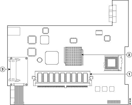
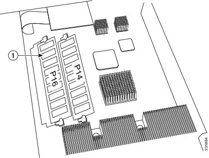
Figure 4-26 System Memory Location in the Cisco ASA 5510
Figure 4-27 System Memory Location in the Cisco ASA 5520 and the Cisco ASA 5540
Note
Step 7
Note
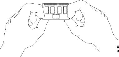
To prevent ESD damage, handle DIMMs as shown in Figure 4-28.
Figure 4-28 Handling a DIMM
Step 8
Step 9
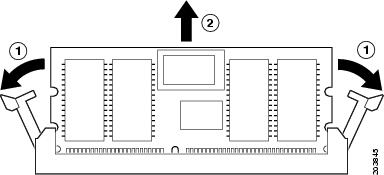
Step 10
Figure 4-29 Releasing the DIMM Latches
Installing the DIMM
To install the memory module, perform the following steps:
Step 1
Step 2
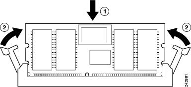
The DIMM is designed in such a way that the connector will fit only one way.
Step 3
Step 4
Note
Figure 4-30 Inserting the DIMM
Caution
Step 5
Step 6
Verifying the Memory Upgrade
Cisco ASA 5510
You can verify that the memory upgrade has been completed successfully by entering the show version command, the example below is for the Cisco ASA 5510 chassis:
hostname# show versionCisco Adaptive Security Appliance Software Version 8.0(4)Device Manager Version 6.1(5)Compiled on Thu 07-Aug-08 20:53 by buildersSystem image file is "disk0:/asa804-k8.bin"Config file at boot was "startup-config"ciscoasa up 2 days 10 hoursfailover cluster up 2 days 11 hoursHardware: ASA5510, 1 GB RAM, CPU Pentium 4 Celeron 1600 MHzBIOS Flash AT49LW080 @ 0xffe00000, 1024KBCisco ASA 5520/40
You can verify that the memory upgrade has been completed successfully by entering the show version command, the example below is for the Cisco ASA 5520 chassis:
hostname# show versionCisco Adaptive Security Appliance Software Version 8.0(0)Device Manager Version 6.0(0)Compiled on Mon 16-April-07 03:29 by rootSystem image file is "disk0:/cdisk.bin"Config file at boot was "disk0:/main_backup.cfg"hostname up 2 days 10 hoursfailover cluster up 2 days 11 hoursHardware: ASA5520, 2 GB RAM, CPU Pentium 4 Celeron 2000 MHzBIOS Flash M50FW016 @ 0xffe00000, 2048KB