Feedback
Table Of Contents
Memory Requirements for Software Version 8.3 and Later
Overview
Read through the entire guide before beginning any of the procedures in this book.
WarningOnly trained and qualified personnel should install, replace, or service this equipment. Statement 49
Caution
This chapter describes the product and the memory requirements, and includes the following topics:
•
Note
Product Overview
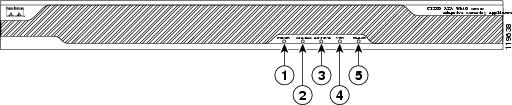
This section describes the front and rear panels. Figure 1-1 shows the front panel LEDs.
Figure 1-1 Front Panel LEDs
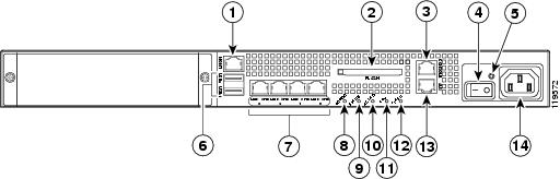
Figure 1-2 shows the rear panel.
Figure 1-2 Rear Panel LEDs and Ports (AC Power Supply Model Shown)
Management port1
USB 2.0 interfaces2
VPN LED
External CompactFlash slot
Network interfaces3
Flash LED
Serial Console port
Power indicator LED
AUX port4
Power switch
Status indicator LED
Power connector
Power indicator LED
Active LED
1 The management 0/0 interface is a Fast Ethernet interface designed for management traffic only.
2 Not supported at this time.
3 GigabitEthernet interfaces, from right to left, GigabitEthernet 0/0, GigabitEthernet 0/1, GigabitEthernet 0/2, and GigabitEthernet 0/3.
4 The RJ-45 Auxiliary port (labeled AUX on the chassis) is reserved for internal use at Cisco. The port is not functional in shipping versions of the chassis; therefore, customers cannot connect to this port to run the adaptive security appliance CLI.
For more information about the Management port, see themanagement only command in the Cisco Security Appliance Command Reference.
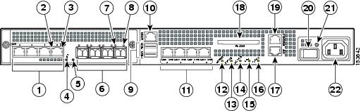
The Cisco ASA 5550 has a fixed configuration with an embedded 4GE slot as shown in Figure 1-3.
Figure 1-3 Rear Panel LEDs and Ports for the Cisco ASA 5550
RJ-45 ports1
USB 2.0 interfaces2
AUX port
RJ-45 Link LED
Management port3
External CompactFlash slot
RJ-45 Speed LED
Network interfaces4
Serial Console port
Power LED
Power indicator LED
Power switch
Status LED
Status indicator LED
Power indicator LED
SFP ports5
Active LED
Power connector
SFP Link LED
VPN LED
SFP Speed LED
Flash LED
1 GigabitEthernet ports, from right to left, GigabitEthernet 1/0, GigabitEthernet 1/1, GigabitEthernet 1/2, and GigabitEthernet 1/3
2 Not supported at this time.
3 The management 0/0 interface is a Fast Ethernet interface designed for management traffic only.
4 GigabitEthernet interfaces, from right to left, GigabitEthernet 0/0, GigabitEthernet 0/1, GigabitEthernet 0/2, and GigabitEthernet 0/3.
5 SFP ports, from right to left, GigabitEthernet 1/0, GigabitEthernet 1/1, GigabitEthernet 1/2, and GigabitEthernet 1/3
Table 1-1 describes the 4GE SSM LEDs.
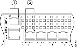
Figure 1-4 shows the adaptive security appliance rear panel LEDs.
Figure 1-4 Rear Panel Link and Speed Indicator LEDs
Table 1-2 lists the rear MGMT and Network interface LEDs.
Table 1-2 Link and Speed LEDs
Left side
Solid green
Green flashing
Physical link
Network activity
Right side
Not lit
Green
Amber
10 Mbps
100 Mbps
1000 Mbps
Note
Memory Requirements
Table 1-3 lists the standard and recommended flash memory and DRAM. Note that the shipping DRAM increased after February 2010; the DRAM requirements for 8.3 and higher match the newer default shipping sizes. See Memory Upgrade Kits for the information to order an upgrade kit. The newer default shipping DRAM is the current maximum DRAM you can install in your unit.
1 For the ASA 5510 through 5550, you might need to upgrade the internal flash memory to 512 MB or add external flash memory if you load multiple images of the AnyConnect client along with one or more images of the ASA software, ASDM, client/server plugins, or Cisco Secure Desktop. In particular, you might need to upgrade for multiple AnyConnect 3.0 and higher clients with optional modules. The ASA 5505 does not have a flash memory upgrade available.
2 The default internal flash memory for some models was 64 MB in the past; if you have one of these early units, we recommend upgrading your flash memory to at least the new shipping default.
In a failover configuration, the two units must have the same hardware configuration. They must be the same model, have the same number and types of interfaces, and the same amount of RAM.
Note
For more information, see the Cisco Security Appliance Command Line Configuration Guide.
Memory Upgrade Kits
Table 1-4 lists the DRAM upgrade kits.
Table 1-4 DRAM Upgrade Kits
ASA 55101
1 GB
ASA5510-MEM-1GB=
ASA 5520
2 GB
ASA5520-MEM-2GB=
ASA 5540
2 GB
ASA5540-MEM-2GB=
1 If you previously purchased the 512 MB upgrade kit for the ASA 5510 (ASA5510-MEM-512=), you must upgrade to the 1 GB memory upgrade kit to run Version 8.3.
Table 1-5 lists the CompactFlash upgrade kits available for the ASA 5510 through ASA 5550, for use as internal or external flash memory.
Table 1-5 CompactFlash Upgrade Kits
ASA 5510 through ASA 5550
256 MB
ASA5500-CF-256MB=
ASA 5510 through ASA 5550
512 MB
ASA5500-CF-512MB=
Memory Requirements for Software Version 8.3 and Later
For information on memory requirements for the adaptive security appliance for software Version 8.3 or later, go to: http://www.cisco.com/en/US/prod/collateral/vpndevc/ps6032/ps6094/ps6120/product_bulletin_c25-586414.html